@WNT Many thanks for your input. I look forward to seeing your direct drive propeller design, please keep us updated.
Cheers Mate.
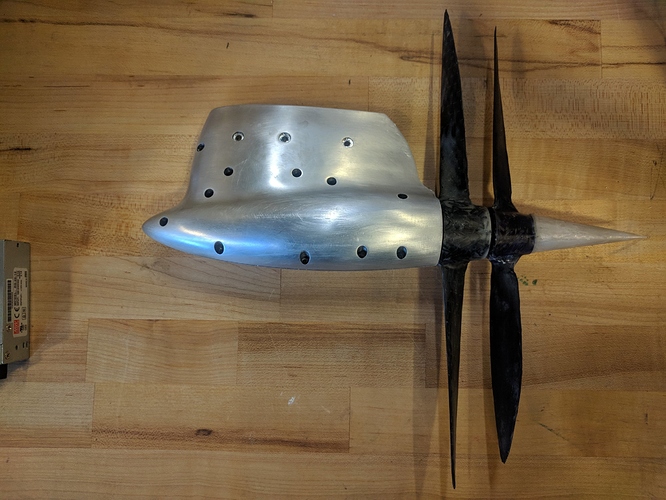
It’s not directly e-foil related, but i designed and built a contra-rotating (not counter rotating ![]() propeller system for a solar powered boat race last year.
propeller system for a solar powered boat race last year.
http://www.taylorpeter.com/#/custom-propellers-design-and-fabrication/
It was my understanding from my research that the CRP isn’t easily modelled, and that no-one has thus far come up with an accurate way to predict performance. Presumably granular enough CFD may come close, but that’s very, very computationally expensive. I went for it because it was an interesting challenge, and i guessed at diameter differences, pitch difference, and spacing. While i’m glad i did it, i do think the benefit is outweighed easily by the added complexity. That extra bearings, bevel gear efficiency losses likely add up to more than the reclaim water spin energy reclaimed. It’s a tough nut to crack.
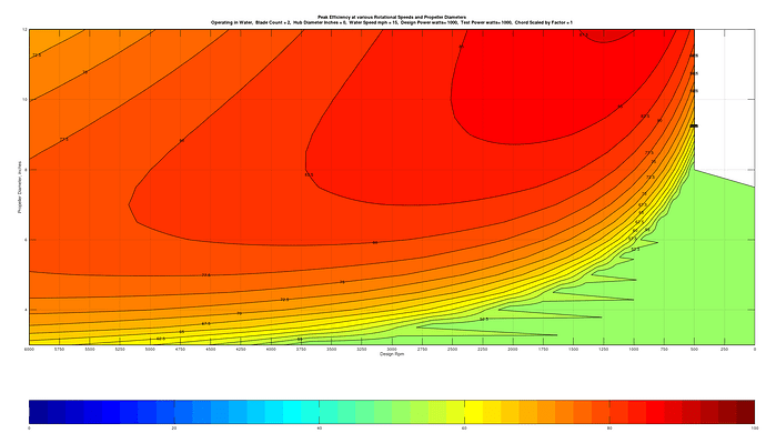
I also wrote a custom front-end for JavaProp, an free propeller design software that iterated through all the various single propeller diameters and speeds, and mapped the peak efficiency at a design speed. My design speed is slower than an e-foil should be designed for, but you’ll spot the trend, and i can re-run this in a few minutes with whatever design speed (water speed) you guys think is interesting. I’m also more limited in power, so my design power was much lower than you guys are willing/able to provide. That’s also an easy thing the change in my graphing script.
http://www.taylorpeter.com/#/solar-boat-2019/
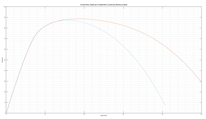
Lastly, i wrote another JavaProp Script that compares Variable pitch, constant speed propellers to constant pitch, variable speed ones. This has a far, far greater efficiency gain than CRP, though with even greater complexity. It’s particularly relevant for hydrofoils, since they experience the drag bucket at low speeds, and they are constrained by propeller geometry at higher speeds. If the geometry can change, low speed takeoff is better, AND top speed is improved, all at increased efficiency. The mechanism is the hard part. There is lots of “prior art” to look at for inspiration though.
Interestingly, in my low speed application (solar boat race) the benefit of variable pitch doesn’t really show up.
ps, i just ran my parameter-space script for numbers i dreamt up for an efoil, lemme know if i should change these.
1000w, 15mph optimal/design speed, diameter range 3-12". Looks pretty interesting. These are unducted propellers.
Different than my application where ~250rpm is optimal (!!!)
Here is seems like 12" (or greater) and 1250rpm is optimal, though 3000rpm and 9" still gets you ~84% optimal efficiency. JavaProp can output an IGES solid model that you can they turn into a real propeller.
edit: each point is a different propeller geometry optimized for that specific diameter and rpm, along with the constant power, water speed etc. This is not a single propeller at different speeds and diameters(obviously?). Some of these might be more efficient at different speeds and whatnot, but are the best they can be for the design conditions.
and here is an efficiency of a good candidate from above.
12" designed for 1250rpm, consuming 1000w.
It shows no major difference at low speeds, but efficiency at higher speed is really dramatically higher than spinning the same prop at variable speeds to consume the same power, rather than tilting the blades to consume the same power. Not also that the motor has it’s own efficiency curve, so the variable speed paradigm is even less efficient than this graph depicts, since if off the motor’s sweet spot.
It’s interesting that the fixed pitch prop just has a short optimum. These simulated propellers are not combinable with our motors though, i think a more realistic output power is 1500W and upwards and then the 9” diameter is too high vs the efficiency range of the motors.
A prop with 4Nm loading at 4000rpm would be great and hit the efficiency spot of the motor better!


