It has jet to fail I thought about using two modules on different positions on the board to give me receiver diversity. This was unnecessary up until now as my board is huge (old windsurfer). I could control the throttle for my sister on the other side of the river (30 to 35 meters maybe) with my phone from the shore. It failed when she went further upstream, but she floated back
The responsiveness is ok for me, but I have not tested the latency to give exact numbers. I see that wifi when in bidirectional mode, so not sending direct frames without ack, is not the ideal solution for this.
That’s quite a project you got going there. I like your solution, espescially the integrated GPS would be nice. I wanted a really compact solution that can be coded quick&dirty. And with mechanical design on a remote I have a few hours into this myself this week and I am currently printing. It takes quite long to CAD something in an ergonomic hosing that’s not only round but with multiple curves.
RPM measurement, at least at static stroke measurement, is very much needed. It allows you to analyze the propeller - if the propeller has an optimal diameter or optimum pitch.
I use a simple optical sensor to measure RPM, I evaluate my impulses on an Android smartphone using a suitable application.
Without engine RPM, you can not optimize the propeller!
I will get a new prop at end of next week. 9" pitch instead of 8". The static thrust is great, but the end velocity is lacking. If this does not help, i will rewind a motor to give more RPM. I motorize surfboard without foil (so far). I have not come to the maximum motor power yet, it is still underloaded.
As I mentioned above, when optimizing a propeller, it is very important to measure RPM. Without RPM measurement, it is not possible to determine if the propeller (impeller) has the correct shape (diameter, pitch, number of blades). The image shows my three RPM measurement probes. I have produced the probes, the largest probe also contains a laser diode (eg for measuring giant wind turbines). I think I will make a waterproof probe. It is also possible to buy or manufacture wireless probes, such as a bluetooth probe. To develop the prototype of the e-foil drive system, the cheapest RPM meter is sufficient.
The display shows 97, this is the flashing frequency of the fluorescent lamp in Hz. The correct value should be 100 Hz. Inaccuracies are caused by applications. The application can be switched to RPM, taking into account the number of blades, costing $ 1. I have another application that would show exactly 100 Hz but can not display RPM. I can connect the probe to an oscilloscope where the measurement is very accurate.
What would be the conclusion, if my static thrust RPM was 3000 and my no load RPM is 4300RPM and my highest RPM driving at full speed 15km/h is 3600RPM? Please give me an idea.
In this situation, when you just estimate the parameters of your drive, I can not estimate anything. When developing a prototype of the propulsion system, it is necessary to proceed very precisely and it is not possible to rely on any estimates. In order for a hydrodynamics specialist to optimize the propeller, he must know not only the RPM propeller at a static stroke, but also
propeller shape and its dimensions (personal tour or 3D CAD)
separate motor parameters and engine parameters after attachment of bearing, seal, cover, etc.
I would like to help the community design a new propulsion system for the hydrofoil, which is cheap, easy to manufacture and still has the best parameters in the world. My help would consist of this:
I would model some parts in 3D CAD
I would suggest a high efficiency propeller optimized for hydrofoil
I would perform some important measurements (tests) of the propulsion system prototype (kg, RPM, V, A)
I would make some measuring devices
This new propulsion system would be a direct drive and included the following:
outrunner engine
one axial bearing (instead of the original radial bearing)
one sealing against water
special aluminum case (can not be bought, must be produced on a lathe), in which the engine will be fully inserted and protected against water penetration, only the shaft will be ejected from the rotary unit
the propeller should be mounted directly on the rotating unit (aluminum case)
Builders of this propulsion system would have no need to measure, they would not have to know the hydrodynamics, they would only be looking for individual components that would be gradually interconnected according to the instructions (like Lego).
First step: I will draw the first simple layout of this new system within a few days!
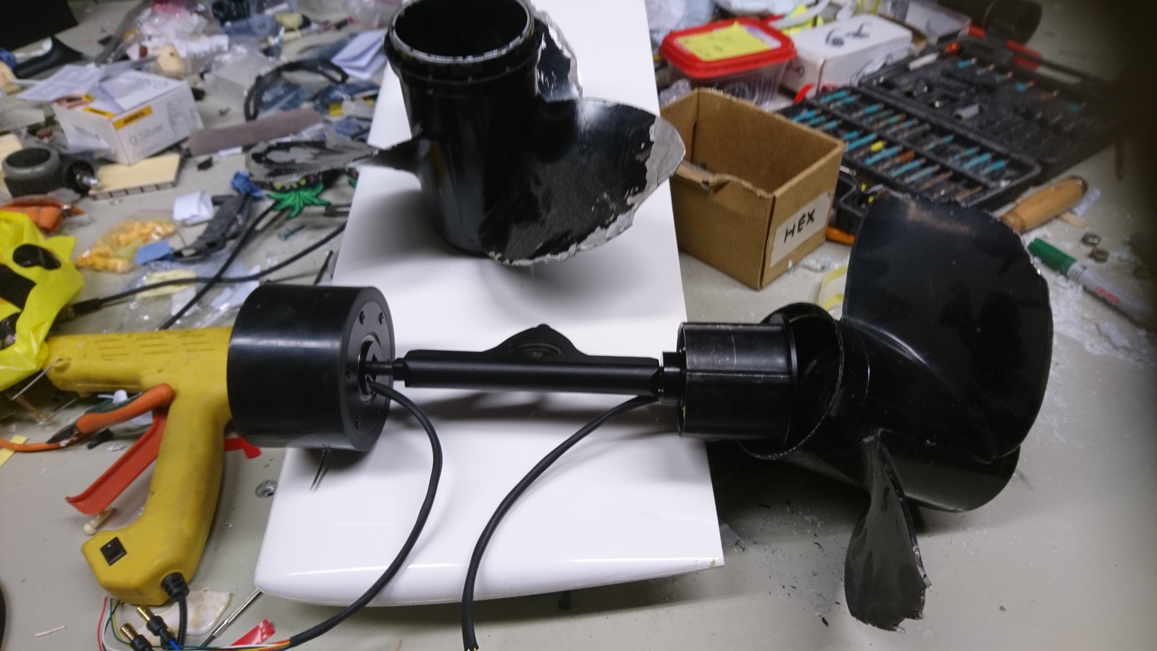
Thats a nice offer. It seems to me you could not fully understand the direct motor direct cooling concept with the motors design, but that is no problem, i will try to explain:
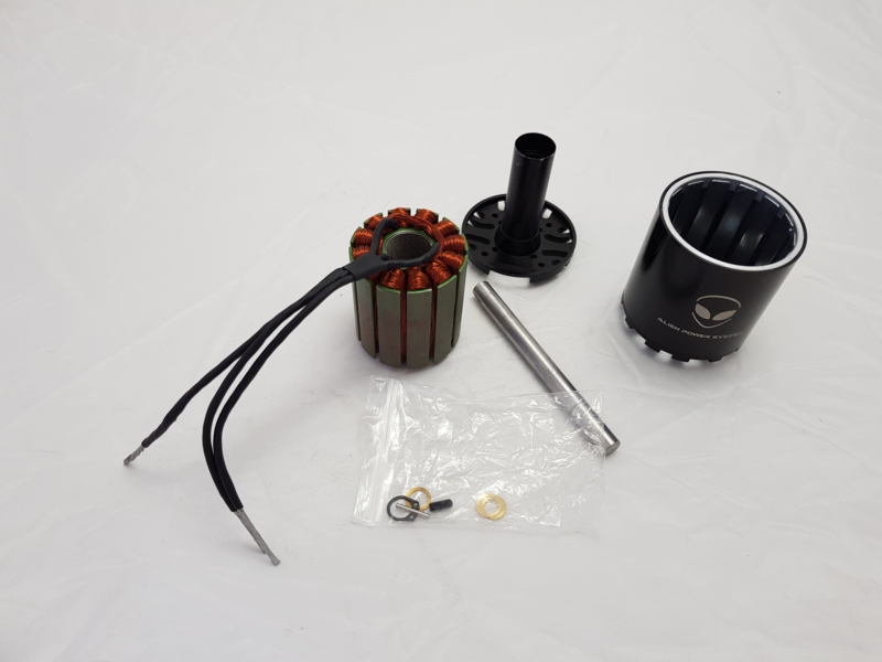
Here you can see the motor i designed with help of APS.
It consists mainly of three parts: the hub made of alu, the stator made of iron sheet with isolated windings and the rotor made of steel, magnets and a spinning alu hub which is assembled to the rod. This rod is supported by 3 radial bearings which also can take the axial load easily. The complete motor is immersed in the water. The water flushes the gap between the stillstanding stator with its windings and the turning rotor bell.
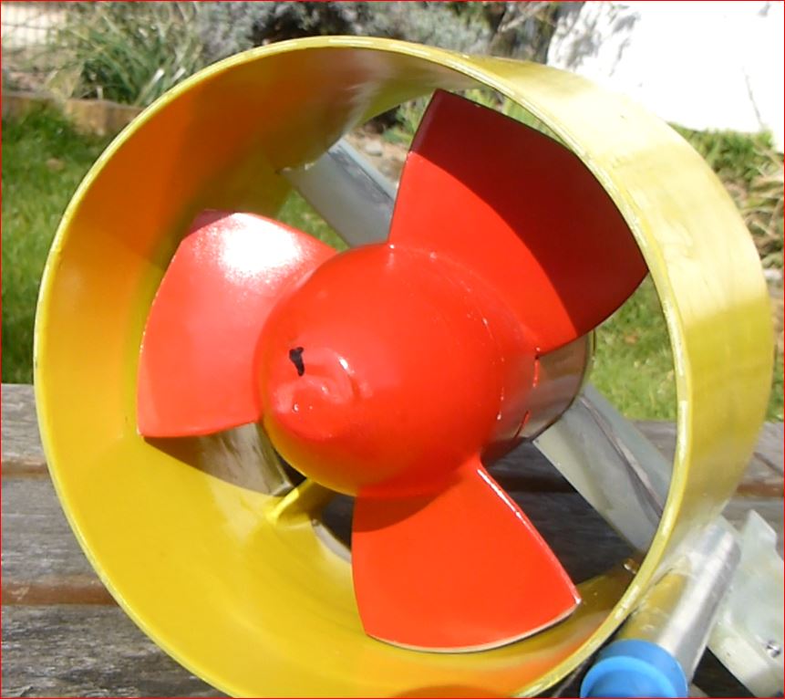
On the hub of the rotor the prop is mounted facing backwards. So the rotor and the prop form a unit which can be optimized.
This prop was made of a 7 1/4 x 5" cut down to 135mm.
There is no need for any seal. Only the phase wires on the stator need some epoxying and tightening when adapting to flexible leads.
Ty @ PowerGlider, I too want to motorize an old 105L alpha carbon fiber windsurfer so I really appreciate your information.
Waterwolf? surfer makes one in Germany, I have posted the link elsewhere and it is very easy to find
Thanks again I will find the info if needed
They are using what looks like a smaller version of the torqueedo propellers the 200 mm diamter one and the 300 mm one but scaled down?
Hi PG I’m building myself an electric skateboard with dual Maytech 9055 hub (outrunner) motors, VESCs and universal battery system. Single hub motor is 65kV 10S 22A max and 800W with ~2200rpm max in air. Rotor is 52x31mm, sensored and magnes about 5x2x35mm. I have heard people getting more amps out of them than rated 22A which is rated continious, I think…
Tho if the rotor be getting magnitude better cooling would it give better performance aswell?
I’m hoping to have a chance with something like this:
Using two hub motors still on their normal trucks, of which’s “t-shape thingy” I would clamp between shells that hold onto a wing (not correct wing pictured)
The outer shells would have thrust bearings on the ends of hubs against either fixed nosecones or clamp shell. I was thinking of taking a mould for blades from a trashed Yamaha 10" pitch prop and then play with the sizes. The propellers would be mounted onto hubs via ~composites
I could force water through stators via holes starting from the lead cone, via 1st rotor, via clamp, via 2nd rotor and then out the end cone. Without slip it would give me ~30km/h?
I’m thinking is it all worth the hazzle… a hundred euros to spend for a specially spec’d motor is nothingburger compared to custom board and wingses n stuff
I think it will work somehow. Expect 10km/h. Sensored version is untested and the complexity is completely unnecessary. If the scrap is laying around, why not? Start, but do not believe it is getting easier over time.
@PowerGlider If you want me to print you a few propellers so you can continue testing power thats no problem! you are making good progress, and a better prop could improve speed a lot!
Thank you, i use aluminium props with hub caps printed in PLA and screwed down into an adaptor. Its not the best solution regarding stability and turbulences, but it helps.
At the moment i test 8" pitch. I plan also 9" test, the prop has arrived but needs lot of treatments on the lathe.
 I thought about using two modules on different positions on the board to give me receiver diversity. This was unnecessary up until now as my board is huge (old windsurfer). I could control the throttle for my sister on the other side of the river (30 to 35 meters maybe) with my phone from the shore. It failed when she went further upstream, but she floated back
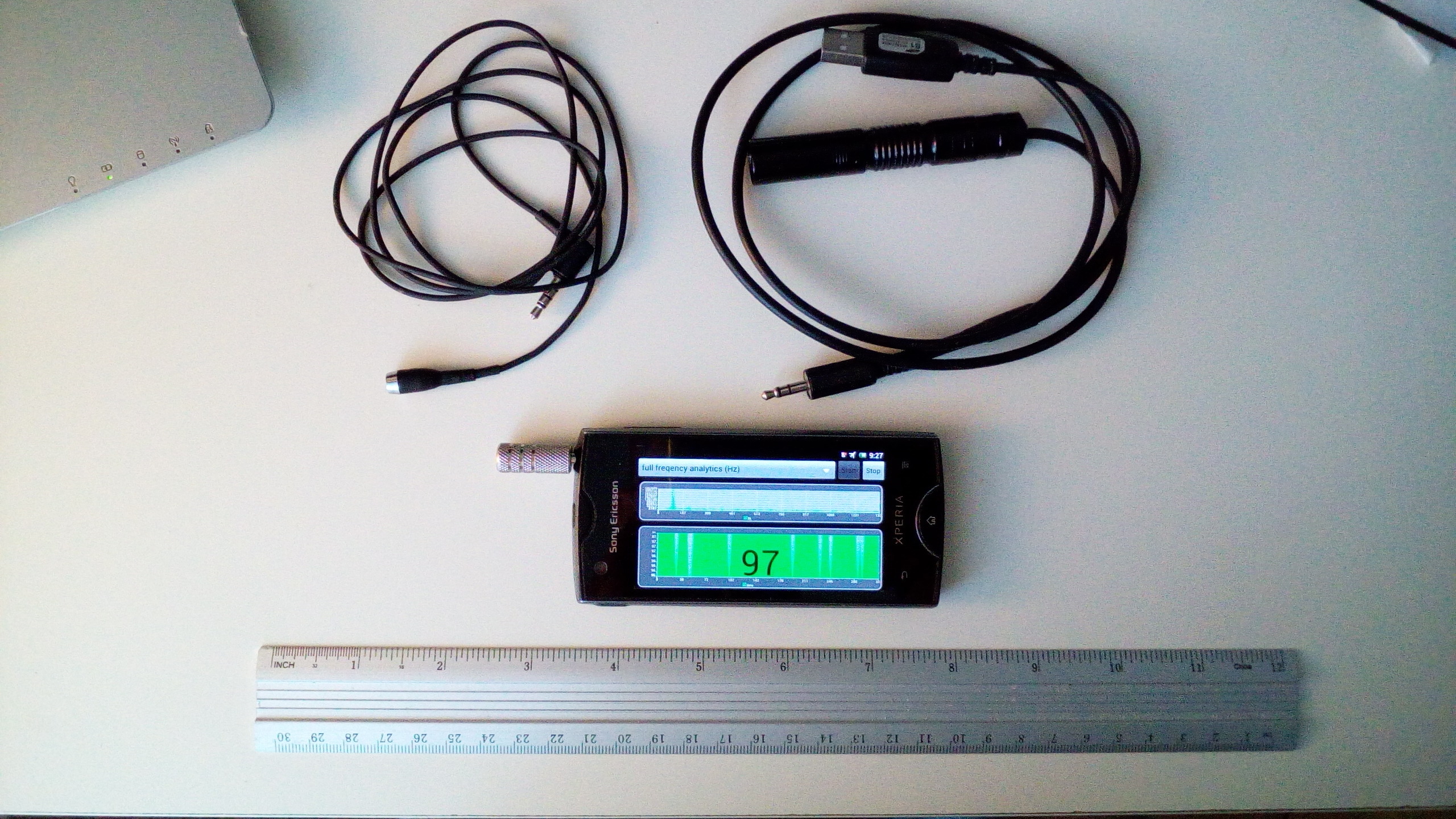
 I’m building myself an electric skateboard with dual Maytech 9055 hub (outrunner) motors, VESCs and universal battery system. Single hub motor is 65kV 10S 22A max and 800W with ~2200rpm max in air. Rotor is 52x31mm, sensored and magnes about 5x2x35mm. I have heard people getting more amps out of them than rated 22A which is rated continious, I think…