# Going down a rabbit hole - Parametric foil design and printable molds in Onshape
**URL:** https://foil.zone/t/going-down-a-rabbit-hole-parametric-foil-design-and-printable-molds-in-onshape/27227
**Category:** Build, Repair & Mod
**Created:** [September 23, 2026, 7:42am UTC](https://foil.zone/t/going-down-a-rabbit-hole-parametric-foil-design-and-printable-molds-in-onshape/27227 "2026-09-23T07:42:22Z")
**Posts on this page:** 20
**Page:** 1
### Author:  [@Jb69](https://foil.zone/u/Jb69)
#### Post date: [September 23, 2026, 7:42am UTC](https://foil.zone/t/going-down-a-rabbit-hole-parametric-foil-design-and-printable-molds-in-onshape/27227/1 "2026-09-23T07:42:22Z")
One caveat before any of it: I know nothing about building a foil. I’ve never laid one up, I’ve never printed a mold, and I’ve only ridden the ones I bought. So read everything below as a modelling exercise by someone who’s about to find out how wrong he is, not advice from someone who’s done it. That’s partly why I’m posting it: plenty of people here have actually built these things, and I’d rather be corrected now than after the resin’s gone off.
This started as a side quest. The [folding prop and the blade generator](https://foil.zone/t/three-blade-folding-prop-experiment/27182)are the original project, but to size a prop you really need a drag curve, and for a drag curve you need a foil, and nine hours on a plane with a laptop open turned “how much drag does my foil make” into something bigger than I meant it to be. It’s near enough done that I’d rather show it than sit on it.

It’s one Feature Studio with six custom features, used in order in a Part Studio. Wing: give it area and aspect ratio, section, sweep, tip drop, washout, incidence, and it solves the planform to hit the area. Stab: same, placed by arm, optionally linked to the wing as a fraction of its area, and it carries the mount pad, tail fairing and bolt pattern, all pinned to the stab pivot so any stab fits the same fuselage. Performance: no geometry, a speed sweep, lifting line for wing and stab, trim, stall, static margin, drag including mast, pod and fuselage, root bending, and with the propulsion group on, the same B-series maths as the blade generator: rpm, throttle, amps, Wh/km, range, top speed, and what the thrust line does to trim. Mast, tapered and thickened toward the plate with a fillet into it and an optional pod. Fuselage, a round tube that spigots into the wing and seats on the stab’s pad. Then the mold feature.
Pick the finished part and it makes the mold. Two shells parted along the camber line’s silhouette so both release, with flanges, locator keys, and a pinch-off groove so the excess resin squeezes out when you clamp it. It tiles the shells to your printer bed with staggered joints and keys between tiles and keeps the joints off the awkward bits. Plugs for the tube socket and the pod come off the part’s own cavities, so if you model your motor’s real shape into the pod the plug follows it. Bolt holes in the stab mount are molded as undersized tapered cones and drilled after cure. The mast comes out in three pieces, left, right and a tray for the plate. Its all parametric so you can choose as much or as little as you want, you can also tune parameters and use the logged data with the included skill for Ai to analyse." becomes "It’s all parametric, so you can choose as much or as little as you want, and you can tune parameters and feed the logged data to the included skill for an AI to analyse.
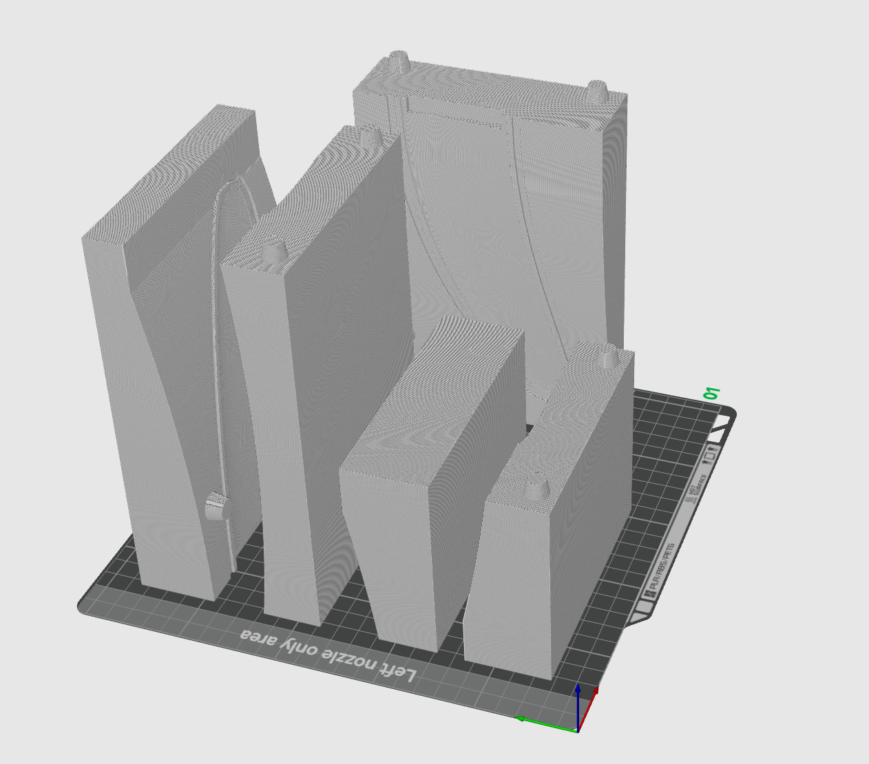
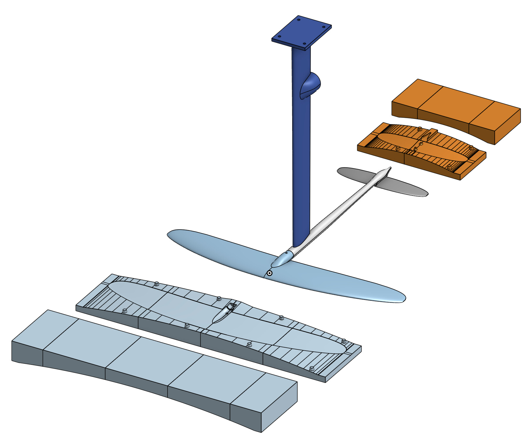
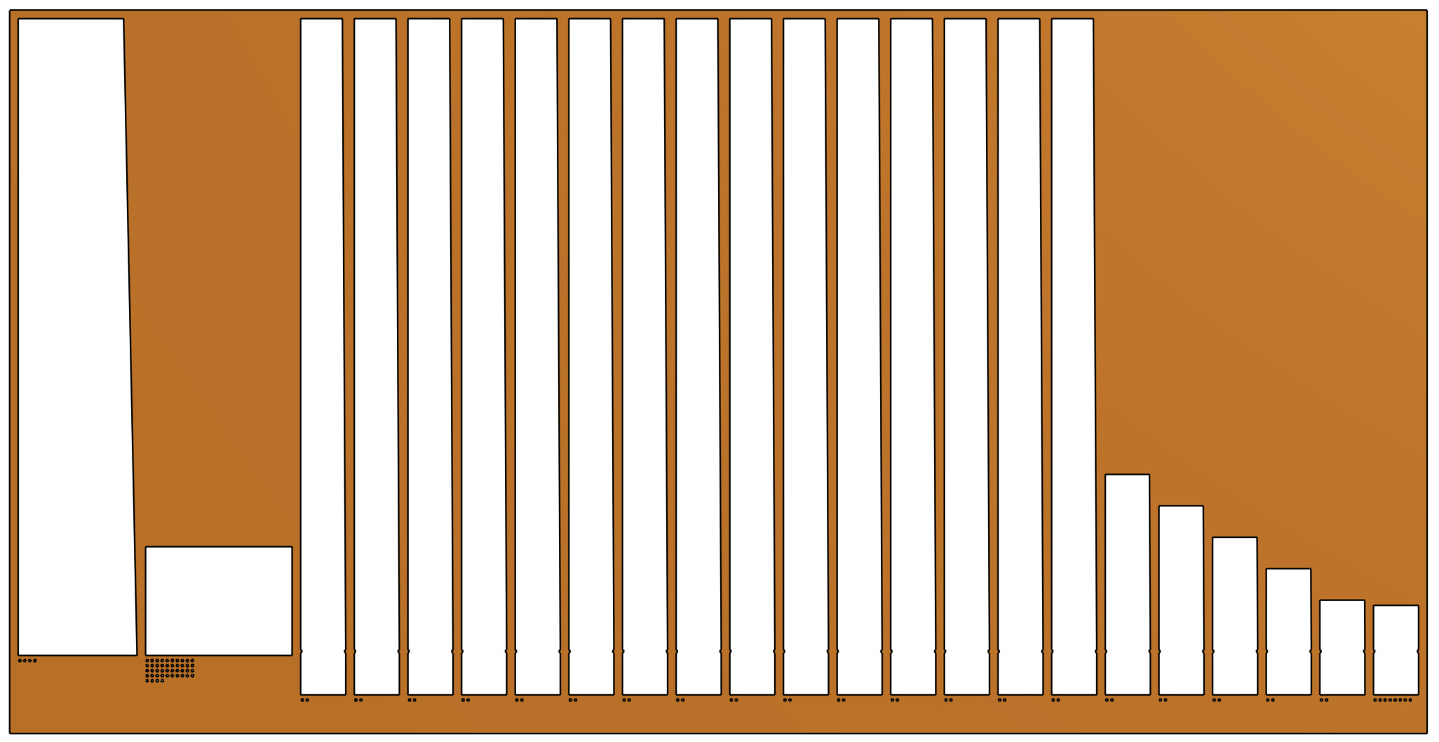
Then the layup, which it works out from the part itself. The volume is the laminate, the surface carries the woven skins, the UD caps are a percentage of the core over a percentage of the chord and taper ply by ply along the span, tow fills the rest. It prints the cut list per cap, the material and resin, and a stiffness check off that layup, deflection and cap stress against the loads the performance sweep produced. For the mast it also checks the plate junction, which turned out to be the weak point until I ran the caps out over a fillet with UD tabs interleaved into the plate. Turn on cut templates and every skin and UD outline lands on a flat plate with tally holes for the cut count, and the top face exports as one DXF.
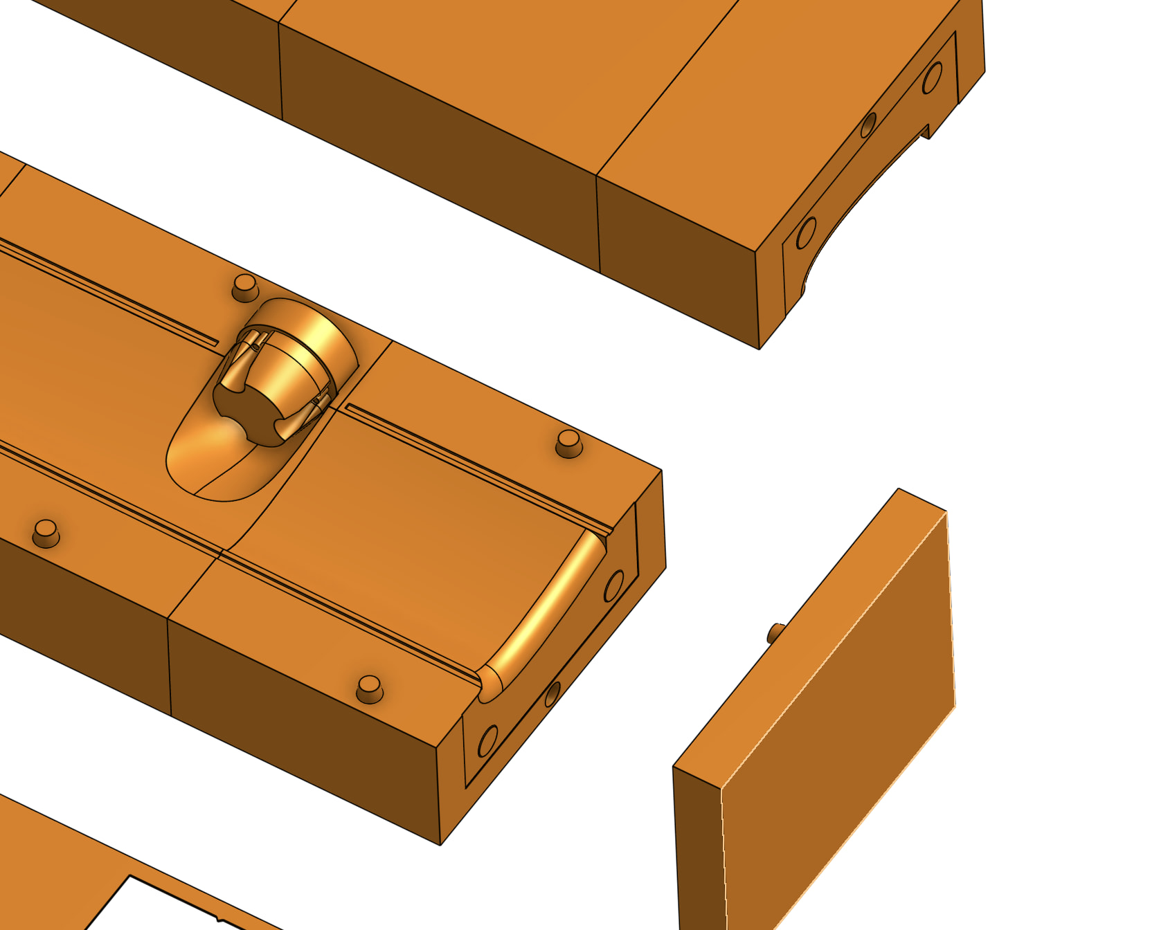
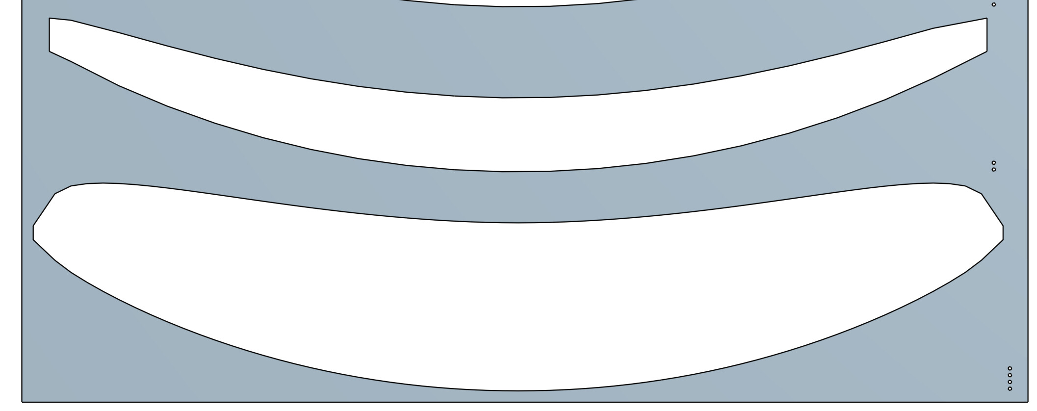
The process it assumes: PLA molds off a bed-size printer and faired for smoothness, wet layup of woven, UD and tow, clamped shut, holes drilled after cure. The plastic is the tool, the foil is carbon.
What it isn’t. It’s not CFD and it’s not dynamic. Every number is steady state: one speed, one weight, flat water, a rider who doesn’t move. Lifting line plus section polars, good for comparing variants, maybe 20–30 % on absolute profile drag. The prop is the B-series open-water estimate. The loads are static, a wing at n g and a mast with a constant side push, and real foils break on peaks and repetition, not averages. No fatigue, impact, buckling or ventilation, and cavitation is a number, not a prediction. What it’s for is that one field regenerates the whole foil, its analysis and its molds, so the trend from one version to the next is trustworthy and you can iterate in an evening. Then you build it and the water tells you the rest.
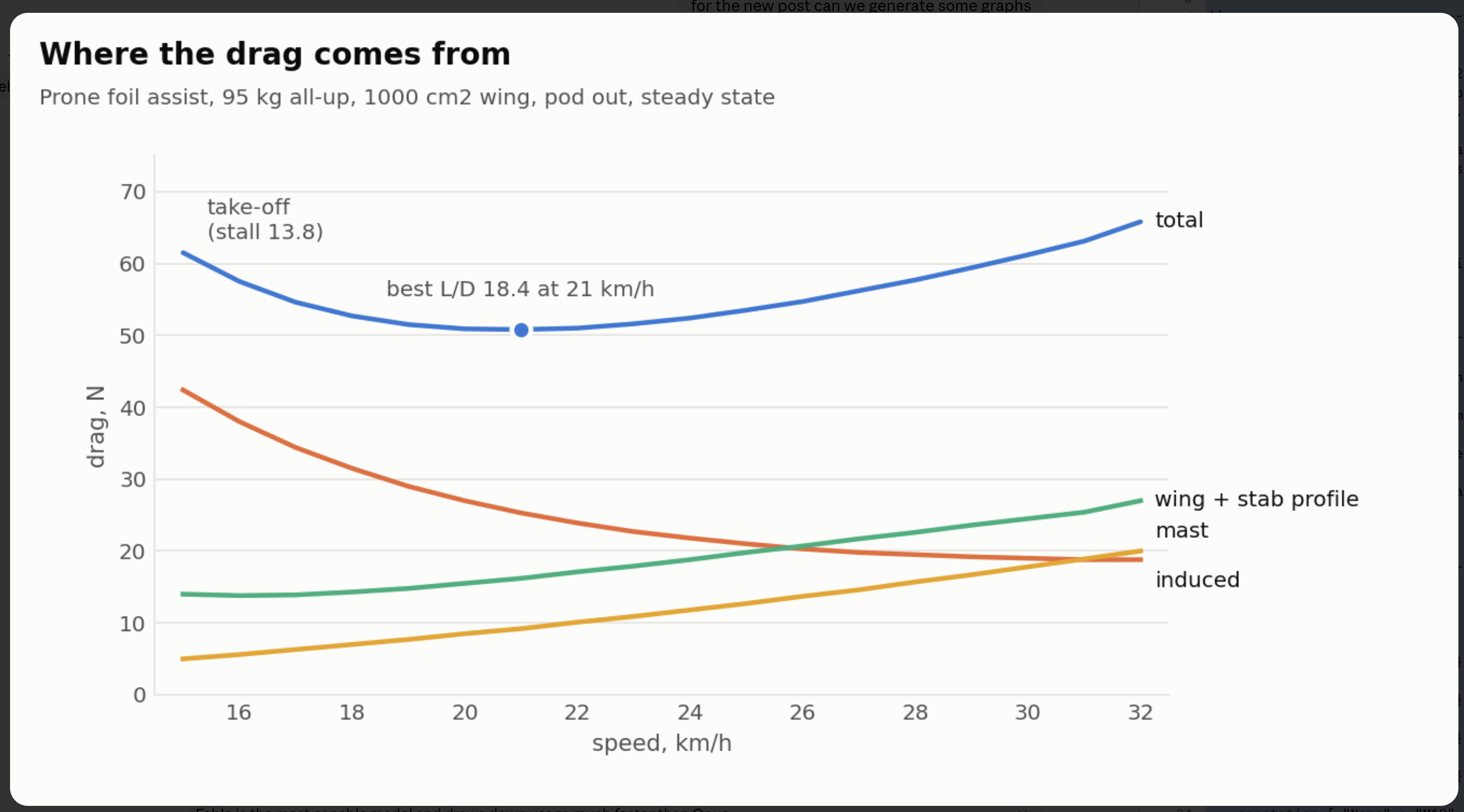
Here’s what it gave for a foil to test the theory.
Prone wave foil assist, 95 kg all-up. 1000 cm² wing, AR 7.2, 850 mm span, NACA 4-digit 3 % camber, 12/10 % thick, 100 mm tip sweep, 30 mm tip drop, 1° washout, 1.5° incidence. Stab linked at 18 %, 180 cm², AR 5.7, symmetric, −1.5°, 660 mm back, two M5 bolts at 35 mm. Mast 750 mm, 100–110 chord, 16 mm going to 22 at the plate from 60 % height, 63 mm pod at 550 mm so it’s out of the water once foiling. 24 mm tube fuselage. Drive: 160 mm three-blade, P/D 0.8, 140 kV direct on 10S, 120 A, 20 Ah.
Pod out, steady state:
| km/h | board angle | CL wing | CL stab | drag N (induced / profile / mast) | L/D | W to hold it |
| --- | --- | --- | --- | --- | --- | --- |
| 15 | 7.4° | 1.04 | +0.05 | 61 (42 / 14 / 5) | 15.2 | 256 |
| 18 | 4.1° | 0.74 | −0.09 | 53 (32 / 14 / 7) | 17.7 | 264 |
| 20 | 2.7° | 0.62 | −0.15 | 51 (27 / 16 / 9) | 18.3 | 283 |
| 25 | 0.4° | 0.42 | −0.25 | 54 (21 / 20 / 13) | 17.4 | 371 |
| 30 | −0.8° | 0.32 | −0.30 | 61 (19 / 25 / 18) | 15.2 | 510 |
Stall 13.8, so safe take-off at 15 is 86 % of the section’s CL max. Best L/D 18.3 at 20. Pod in adds about 7 N and drops L/D to 15.4.
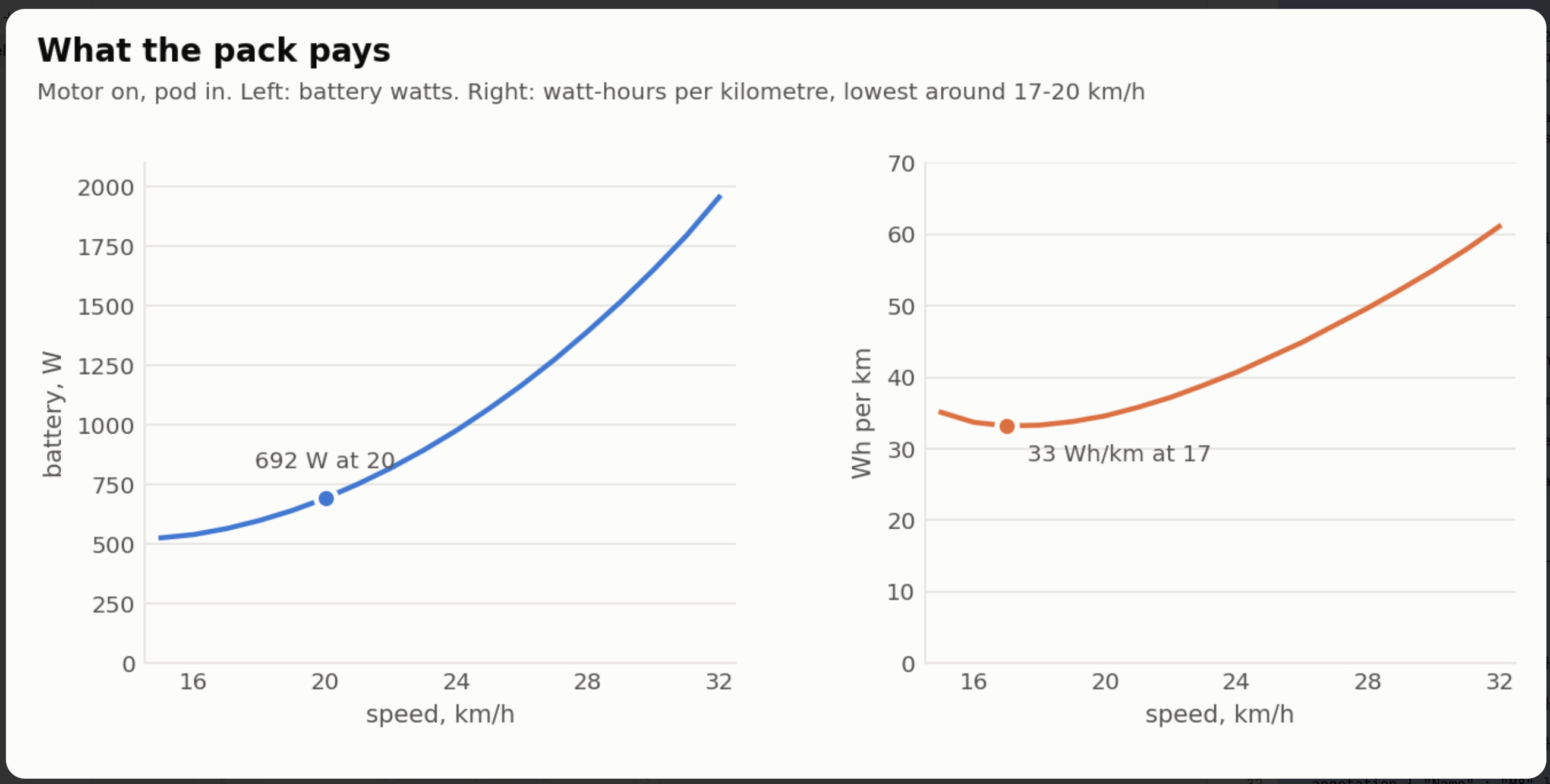
Motor on, pod in:
| km/h | thrust N | rpm | prop eff | motor A | throttle | battery W | Wh/km |
| --- | --- | --- | --- | --- | --- | --- | --- |
| 15 | 67 | 2150 | 69 % | 30 | 46 % | 526 | 35 |
| 20 | 61 | 2590 | 63 % | 33 | 54 % | 692 | 35 |
| 25 | 68 | 3130 | 58 % | 42 | 66 % | 1069 | 43 |
| 30 | 81 | 3690 | 54 % | 55 | 79 % | 1651 | 55 |
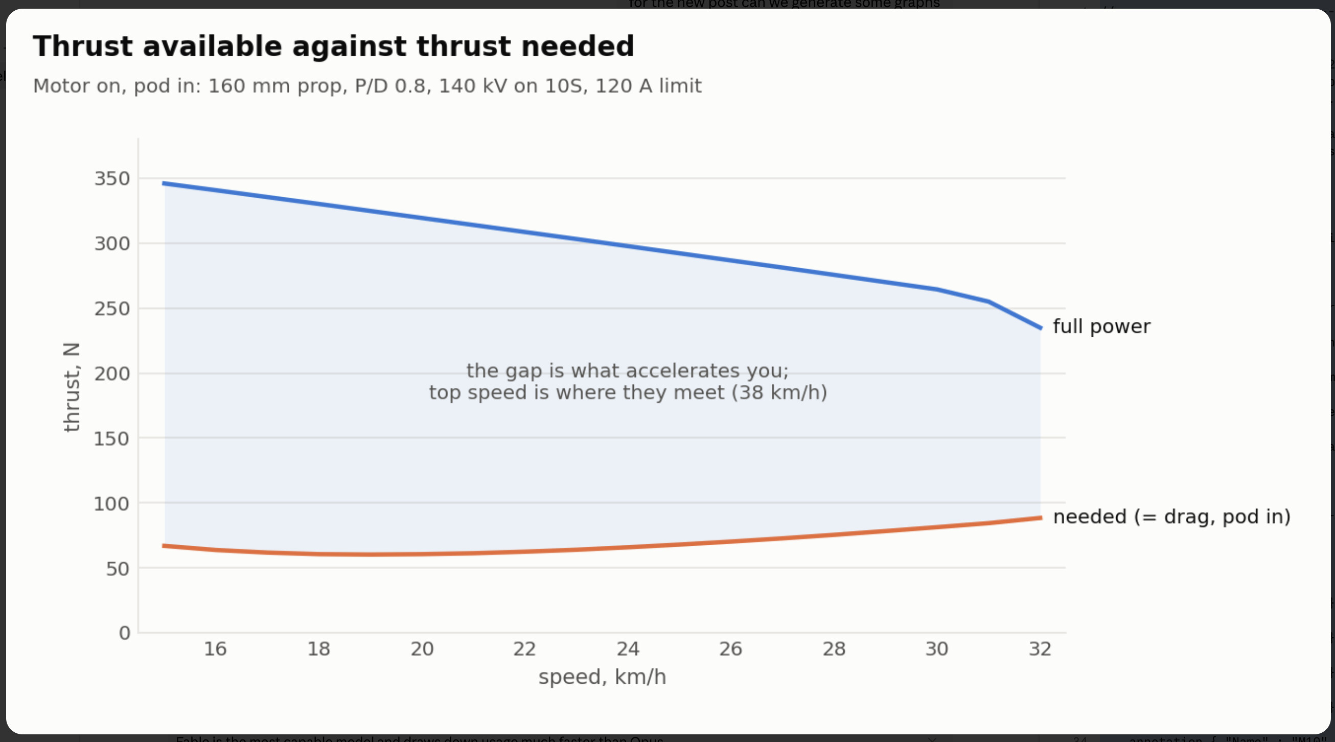
41 kgf static, top speed 38, 19 km or about an hour if you cruised on the motor the whole time, which on a wave board you won’t. V\_S, you’ll notice the rpm: direct drive at 140 kV on 10S sits at 2600 at 20 km/h for the prop.
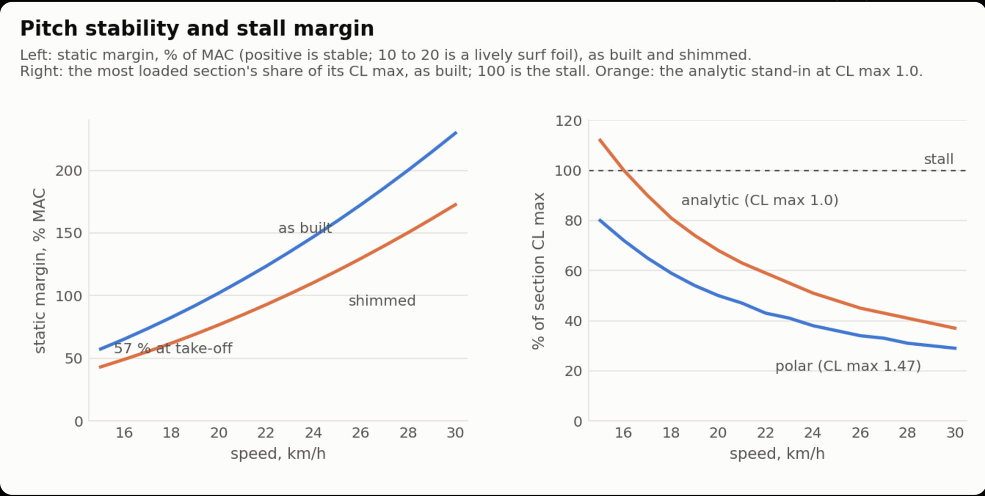
Pitch is the interesting one. Gliding, static margin is 30 % of MAC at take-off and 53 % at cruise. Under power the thrust line is 560 mm above the wing and 450 mm above where the drag acts, a 33 Nm nose-down couple at take-off, and the powered margin at 15 km/h comes out at 0.2 %. Neutral. You stand about 37 mm further back with the motor on. My first go had the pod 50 mm higher, a 150 cm² stab at 620 mm and 2° decalage and came out at −16 %, which I think is the number behind every “foil assist wants to nose in on the motor” post. Lowering the pod is the fix, and it’s the one lever the commercial kits can’t pull without putting the pod back in the water.
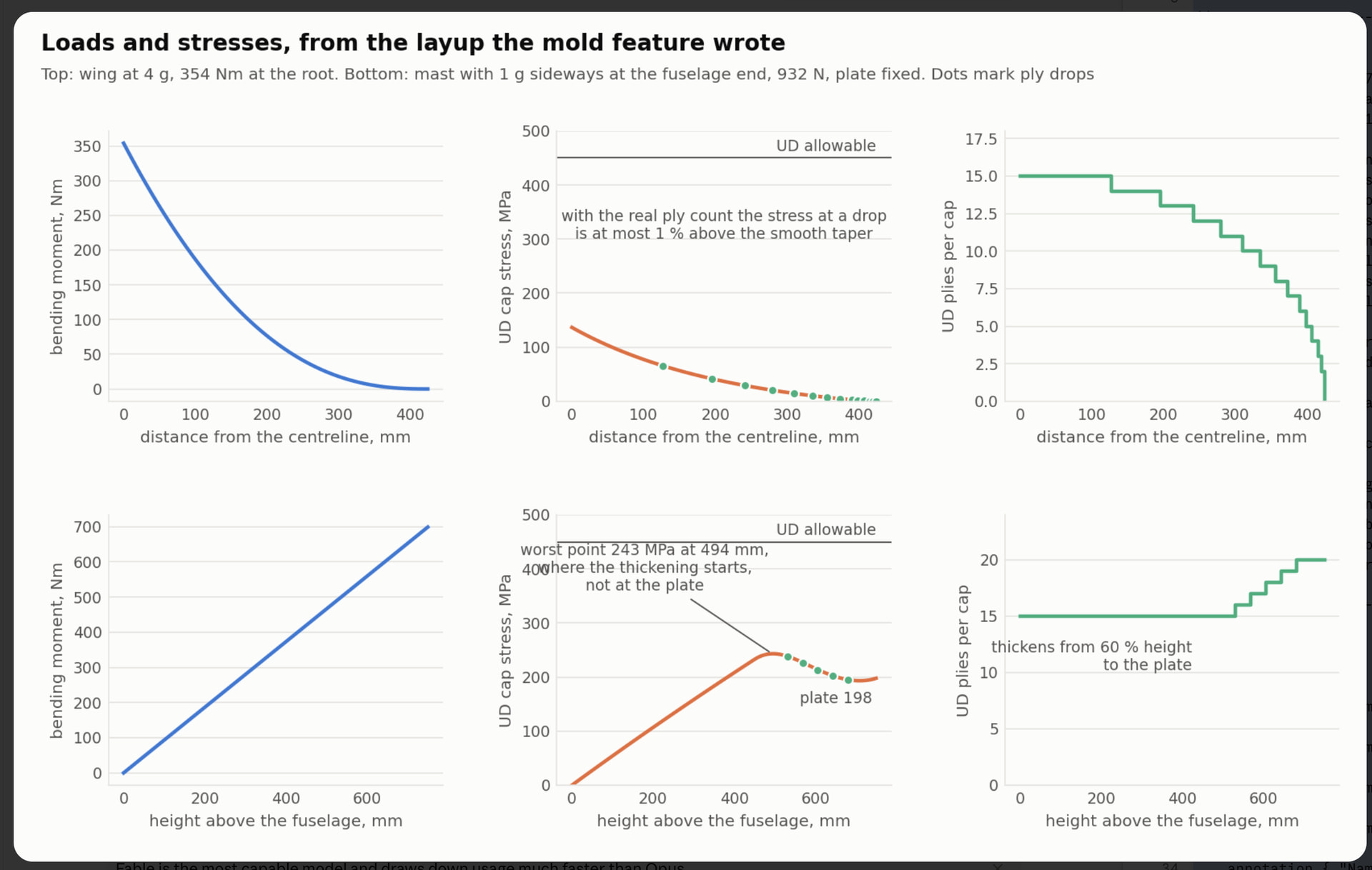
Structure, from the layup the mold feature wrote:
| part | case | layup | deflection | cap stress |
| --- | --- | --- | --- | --- |
| wing | 4 g, 354 Nm at the root | 2 × 200 g woven each face, 15 UD plies per cap tapering to 4, tow core | 6.5 mm at the tip | 137 MPa |
| stab | 4 g | same skins, 5 UD per cap | 1.9 mm | 100 MPa |
| mast | 1 g sideways at the fuselage, 932 N | 20 UD per cap at the plate, 15 at the foot, 4 tabs per face into the plate | 53 mm at the fuselage end | 198 MPa at the plate |
Mast junction 38 kN cap force, 2.1 MPa shear against 15 allowed, 3.9 kN per track bolt, 96 MPa in the plate. Wet-laid UD is good for 450 or so, so there’s a factor of two at loads a wave session won’t see.
Materials at 50 % fibre: wing 1.6 kg (0.43 m² woven, 1 m² UD, 600 g tow, 830 g resin mixed), stab 0.13 kg, mast with plate 1.9 kg. About 3.7 kg of carbon and epoxy for the three molded parts. Wing mold 225 × 899 × 91 in nine tiles for a 250 mm bed, stab in two halves with the cones, mast in three.
Photos of the molds and the template plate to follow. Sections are a dropdown with built-in polars, NACA 4-digit, E817, E818 and NACA 63-412 from their coordinate tables, or add your own: there’s a polar group that takes thirteen numbers off an XFoil run so stall and drag come from the real section rather than thin-aerofoil theory. Yes, it’ll be public on Onshape next to the blade generator once I’ve found what else is wrong. There’s a PDF guide half written.
The bit that brings this back to the prop. Everything the mold feature had to learn the hard way applies straight to blades and hubs. Part along the camber line of each section and both halves release. Print the locator keys into the flanges with a bit of draft. Put a pinch-off groove round the cavity so the clamp squeezes the flash out instead of the laminate. Mold holes as undersized tapered cones and drill them after cure, never try to mold a bore to size. Take any plug or core off the part’s own cavity, so the pivot bore, the gear pocket and the shaft bore in a folding hub come out as cores of the mold rather than things you model twice. Tile to the printer bed with staggered joints so a 200 mm blade doesn’t need a big printer. A blade is just sections along a radius instead of a span, and a hub is a lump with holes in it, which is easier than a wing with a socket. So the next thing the blade generator could get is a mold feature: pick a blade, get two shells and a plug; pick the hub, get the same.
What I’d like to know from people here is which bit is actually useful, the mold and layup side, the performance side or the range stuff, and if anyone has measured drag or deflection on a known foil I’d like to check the model against it.
End game it kept me entertained on the flight.
---
### Author:  [@Jan12](https://foil.zone/u/Jan12)
#### Post date: [September 23, 2026, 10:02am UTC](https://foil.zone/t/going-down-a-rabbit-hole-parametric-foil-design-and-printable-molds-in-onshape/27227/2 "2026-09-23T10:02:03Z")
Amazing.
Foil - you usually want multiple sections.
One reason alone is with the new smaller stabs, you have a relatively wide base and if you use the same foil section everywhere, either the base gets very thick or the rest too thin to build.
The results of your calculation are not realistic.
Not completely off, but 13.8 km/h or even 15 km/h stall speed is not going to happen with a foil like that. I’d assume its in the 18 km/h range in the real world.
---
### Author:  [@Jb69](https://foil.zone/u/Jb69)
#### Post date: [September 23, 2026, 11:05am UTC](https://foil.zone/t/going-down-a-rabbit-hole-parametric-foil-design-and-printable-molds-in-onshape/27227/3 "2026-09-23T11:05:28Z")
Thanks Jan, both fair.
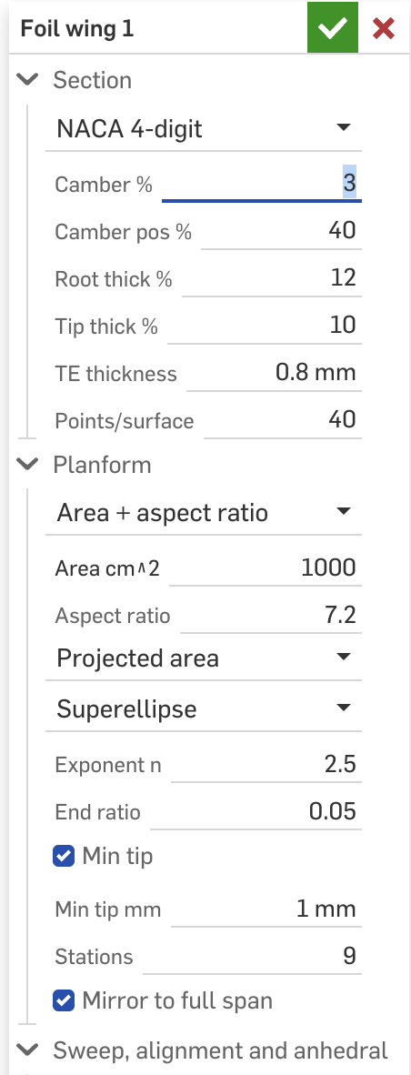
On sections: it’s not quite one section everywhere. Thickness ratio runs from root to tip on its own curve (12 to 10 % on the wing, 10 to 8 on the stab), and there’s a minimum absolute tip thickness underneath that. On this wing the tip chord is about 6 mm, so 10 % would be 0.6 mm and it gets held at 1 mm so it can actually be laid up. So the “base too thick or tip too thin to build” problem is covered. What it doesn’t do yet is change the section shape along the span, a cambered root blending to a flatter tip. That’s next on the list and I’d be interested in what you’d blend between.
On stall: I think you’re right, and it’s the number I trust least. The 13.8 is the speed where the most loaded bit of a perfect section hits its 2D CL max in dead steady flight, with a rider who doesn’t move. Lift goes with CL max, so your 18 km/h works out to an effective CL max of about 0.75 against the 1.27 the section polar gives. There’s a knob for that, but I’d rather set it from something real than guess. What’s the lightest you’ve seen a wing of about this size (1000 cm², AR 7) fly at, and what weight? One real take-off speed and I can calibrate the lot.

---
### Author:  [@Jan12](https://foil.zone/u/Jan12)
#### Post date: [September 23, 2026, 1:59pm UTC](https://foil.zone/t/going-down-a-rabbit-hole-parametric-foil-design-and-printable-molds-in-onshape/27227/4 "2026-09-23T13:59:29Z")
> [@Jb69](#):
>
> So the “base too thick or tip too thin to build” problem is covered
Take a look at these, as they are the current “meta” for stabs it seems:
> **[U Carve Stabilizer - AFS](https://afs-foiling.com/product/u-carve-stabilizer)**
>
> U Carve: glide, precision, and pure carving feel. The U Carve range has been designed around a full base concept, with a generous footprint to ensure rigidity and a precise feel. Its reduced wingspan and refined tips refocus the lift: roll is...
At the root, where the screws are, you want a much thinner profile than in the main area, or you would have a large bump there. In this case the profile is also one that is flat on one side.
Can’t tell you exact takeoff speed for a foil like this, but I think 18 km/h is an OK guess.
Maybe someone who is doing logs in flatwater is having a better idea.
---
### Author:  [@Jb69](https://foil.zone/u/Jb69)
#### Post date: [September 23, 2026, 2:41pm UTC](https://foil.zone/t/going-down-a-rabbit-hole-parametric-foil-design-and-printable-molds-in-onshape/27227/5 "2026-09-23T14:41:37Z")
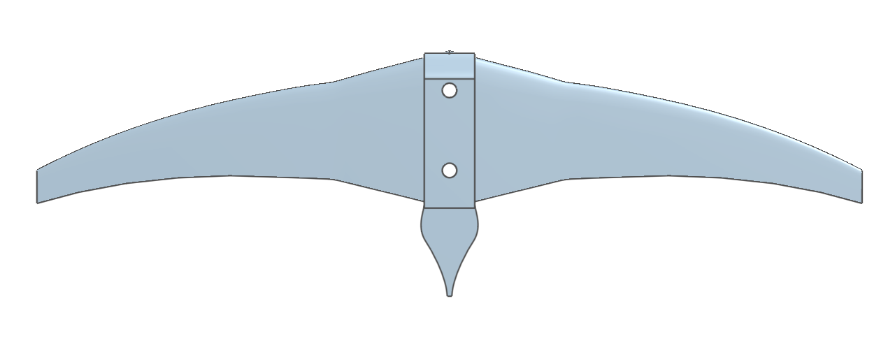
Jan, I measured the U Carve 130 off AFS’s product picture and scaled it to their 130 cm², and it comes out at 361 mm span and 68 mm root chord against their published 360 and 68, so the picture is true to the part. The outline is two straight tapers: a steep one to about 28 % of the half span, where the chord is 62 % of the root, then a gentle one out to a 14 mm tip. A superellipse can’t do that, it misses by 12 %; the two tapers match to 1.5 %.
So that’s now a third chord option, double taper, with the break and the two ratios as inputs, and the thin root is just the thickness running the other way, 7.4 % at the root and 9 outboard, which it already did. And there’s a Clark Y profile now for the flat side, mounted flat face up to the fuselage. I’ll model the U Carve set and post what the solver makes of it, and what it says the drag and stall look like next to the symmetric stab I had.
Needs a little bit more work
---
### Author:  [@Jb69](https://foil.zone/u/Jb69)
#### Post date: [September 24, 2026, 5:56am UTC](https://foil.zone/t/going-down-a-rabbit-hole-parametric-foil-design-and-printable-molds-in-onshape/27227/6 "2026-09-24T05:56:08Z")
Jan’s pointer to the U Carve sent me down a second hole, and I came out of it with an AFS Silk V2 950 and a U Carve 130 modelled in the tool, molds and all. Posting it because it’s the first time the thing has been checked against real parts with published numbers rather than my own guesses.
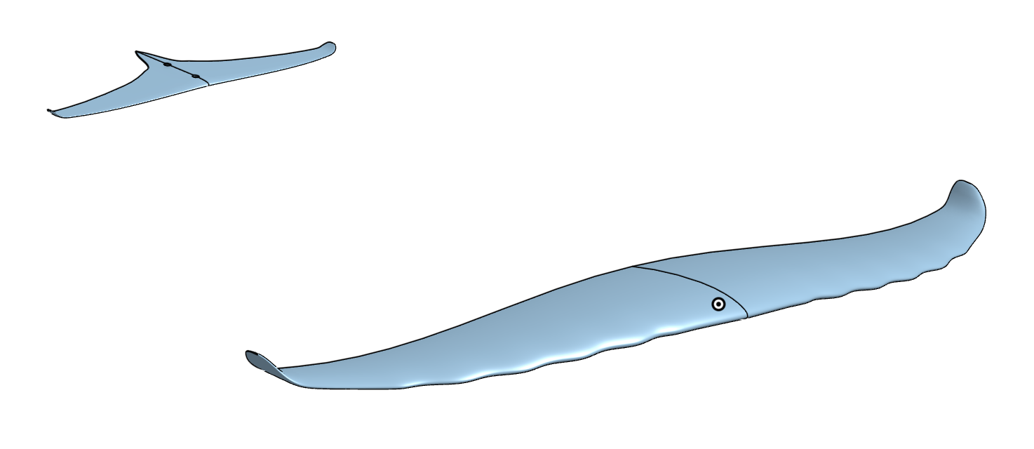
**How.** AFS publish area, span, max chord and thickness for every size, and their product renders turn out to be true to scale. So I measured the outlines off the renders, scaled by the published span, and fitted the tool’s chord laws to them. The check that it’s not nonsense: the fitted root chord lands within 3 to 8 % of AFS’s published max chord on every wing in their range, and the Silk 950 comes out at 925 mm span and 143 mm root against their 925 and 140. What I can’t get from a render is the section, the camber or the twist, so those are guesses and I say so wherever they appear.
**What it took to draw them.** The tool couldn’t do either shape when Jan posted. Since then, in the order the parts demanded them:
- Double taper chord with a blended break, for the U Carve’s full base (and it turns out AFS’s Evo HA front wing is the same shape).
- Clark Y as a profile, flat side up on the stab as Jan described.
- Tips rounded in plan as well as thickness, with the rounding centred so both corners round.
- A root tail on the stab, so the V behind the root is part of the stab, not the mount.
- Winglets: the outer part of the span bends through an angle on a radius, with the sections drawn square to the bent path.
- Leading-edge bumps, the tubercles, as geometry only. Six stations per bump, and the performance model can’t see them, which I’d rather say than pretend.
- The gull front view. The Silk’s span line measures as an S: level at the centre, steepest mid-span, level again by 90 %, then the tips rise. A smoothstep between 3 and 91 % of the half span with 45 mm of drop fits it to 0.3 mm. That’s now a drop shape option, and the tip rise is the winglet on top.

**And to build them.** The layup estimate used to assume a tow-filled section, which put the Silk at 1.33 kg against AFS’s published 900 g. So the core became an option: tow, foam, monolithic, or a 3D-printed core. With a Corecell-type foam it’s 0.62 kg, and with a PLA core it’s 0.87. The mold feature will now also make a mold for the foam core itself, sections less the skins with grooves for the UD caps, open at both tips so a poured foam can expand out; or it generates the printed core as a part, split to the printer bed with dowel holes across the joints.
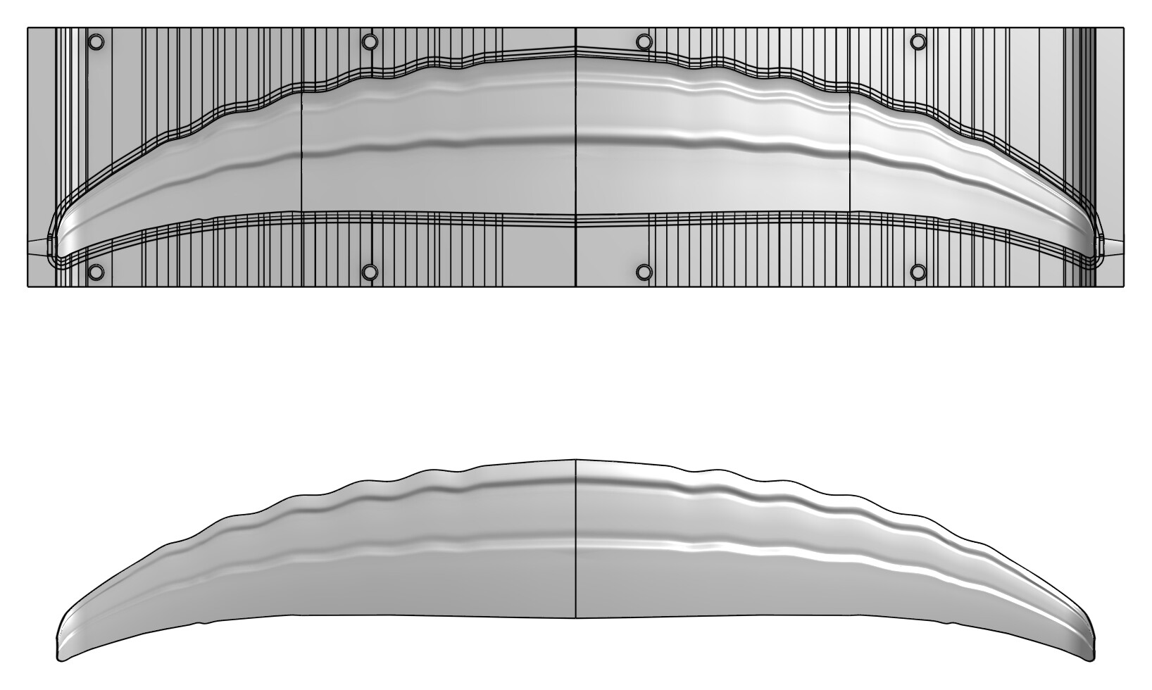
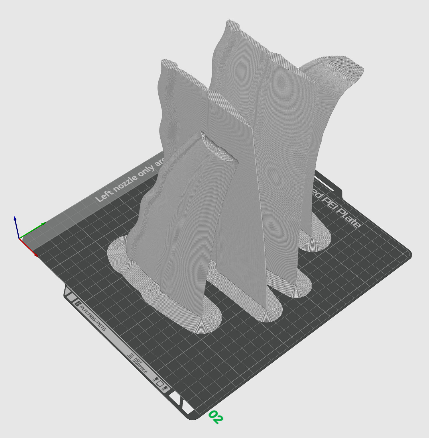
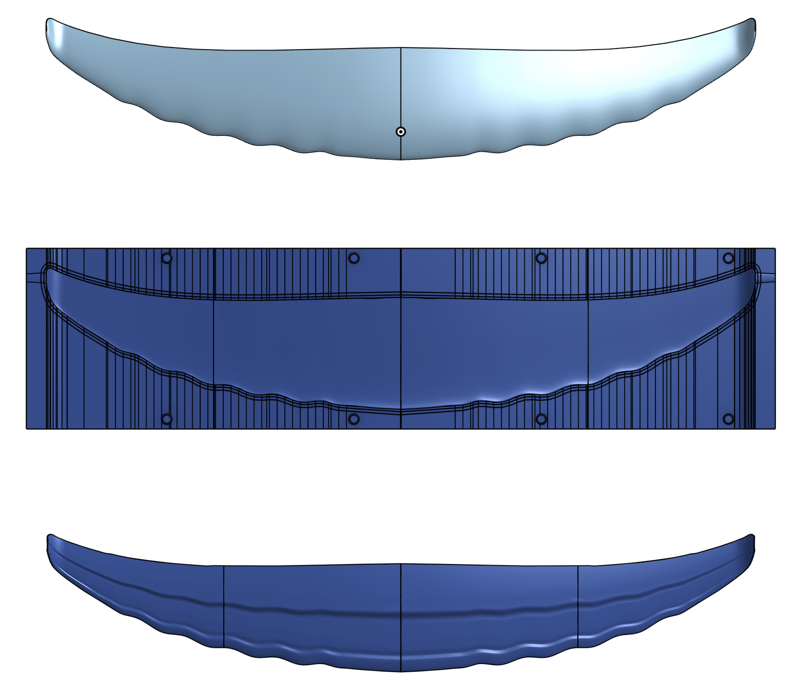
**Numbers, with the usual caveat that every one is steady state.** Silk 950 with the U Carve 130 at 560 mm, 85 kg all-up, no mast or fuselage in the model yet, so add 10 to 15 N to the drag:
| | |
| --- | --- |
| Stall | 15.3 km/h (take-off at 18 is 75 % of CL max) |
| Best L/D | 19.3 at 18 to 19 km/h |
| 22 km/h cruise | L/D 18.4, 45 N, 277 W |
| 36 km/h | L/D 10.5, 79 N, 794 W |
| Static margin at take-off | 52 % of MAC, which is a lot; the flat-sided stab section carries about 3.6° of its own decalage, and I still have the stab at −1.5°, so this is the next thing to tune, not a verdict on the foil |
| 4 g root bending | 359 Nm |
| Wing layup | 2 × 200 g woven each face, 16 UD plies per cap at the root tapering to 3, 130 MPa in the caps against 450 allowed, 10 mm tip deflection at 4 g (2.5 mm at 1 g) with the foam core |
| Weight | 0.62 kg foam core, 0.87 printed core, against AFS 0.9 with their mount hub |
AFS’s own size guide puts the 950 as the small-wave surf sweet spot and points heavier riders at the 1050 and 1150; at 95 kg the model said it couldn’t take off at 15, which is the same advice arrived at the other way.
**The bit I found useful beyond these two.** Doing all 13 of their families gave a table that reads like a design rule book: every front wing 11 to 13 % thick whatever the aspect ratio, so millimetres follow chord; AR by discipline exactly as expected; a straight trailing edge on surf and race wings and a straight leading edge on the high-aspect ones; bumps only on the pumping and surf wings; stabs 5 mm thick regardless of chord and 14 to 17 % of the wing on 650 to 680 mm fuselages. That’s all in the guide now, with a parameter document per family.
Jan, thanks again; the double taper and the Clark Y are both on you. What I’d still like from anyone who rides a Silk with a U Carve is the shim they run, and a take-off speed. Both would calibrate the two numbers I trust least.
**The parameters.** Everything not marked measured is a guess or AFS’s published number.
Foil wing, Silk V2 950: Area 950, Aspect ratio 9, Projected area. Profile NACA 4-digit, Camber 3 %, Camber pos 40 % (guess). Root thick 11.9 %, Tip thick 9.9 % (AFS’s 16.7 mm on 139.8). Chord distribution Superellipse, Exponent 1.4, End ratio 0.26 (measured). Align line 78 %, Sweep aft 67 mm, Sweep exp 4 (measured). Drop shape S-curve, Tip drop 45 mm, Drop from 3 %, Drop to 91 % (measured). Winglet Up, area 15 cm², angle 60°, radius 25 (my guess at their tip rise). LE bumps on, height 5 mm, pitch 59 mm, from 15 to 82 % (measured). Tip cap Rounded + plan, cap 18 mm, cap end 25 %. Min tip 1 mm. Stations 9.
Foil stabiliser, U Carve 130: Independent, Area 130, Aspect ratio 10. Profile Clark Y, Invert section on, Section data Built-in (the flat side, per Jan). Root thick 7.4 %, Tip thick 9 % (AFS’s 5 mm on 68). Chord distribution Double taper, Break 28 %, Mid ratio 0.62, Blend 10 %, Tip ratio 0.21 (measured). Align line 0, Sweep aft 15 mm, Sweep exp 4. Root tail on, 25 mm over 10 %. Tip cap Rounded + plan, 8 mm, 20 %. Arm 560 mm, Incidence −1.5° (the number I said needs tuning). Two M6 bolts at 35 mm.
Foil performance: 85 kg, 18 / 22 / 36 km/h, Section CL max 1.0, 4 g. Foil mold: 2 × 200 g skins, 300 g UD, caps 40 % chord and 60 % of the core depth, Vf 50 %, foam core 85 kg/m³ or printed core at 580.
---
### Author:  [@Jb69](https://foil.zone/u/Jb69)
#### Post date: [September 24, 2026, 7:04am UTC](https://foil.zone/t/going-down-a-rabbit-hole-parametric-foil-design-and-printable-molds-in-onshape/27227/7 "2026-09-24T07:04:01Z")
Second pair, and a more interesting one: the AFS Ultra 900 with the U Glide 43, their downwind combination. Same method as the Silk, outline and bumps measured off their renders and scaled by the published span, plus this time a front-view render to measure the span line from.
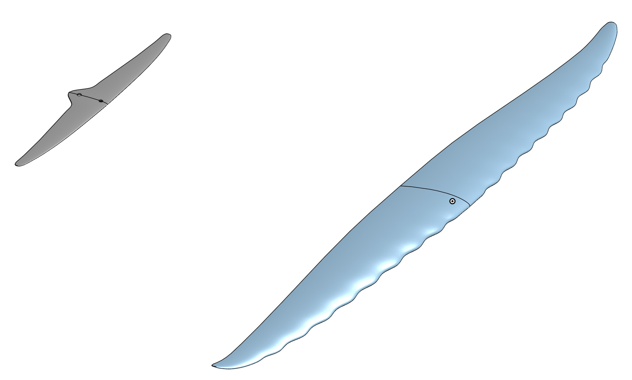
**What the front view said.** I had the Ultra down as nearly flat with a small winglet. The render says otherwise: level from the root to about 15 %, an S-curve drop of 21 mm that is steepest at mid-span and level again by 85 %, then the tips curl up 12 mm over the last 15 %. The Silk’s line is the same shape with more drop. So the S-curve drop that the Silk forced into the tool turned out to be the AFS house style, not a one-off. The curl needed one more lesson: a winglet with a short bend radius and a straight leg reads as a kink, so for a curled downwind tip the radius goes up to the winglet’s own length and the whole thing is the arc.

**Numbers, steady state, 85 kg all-up, no mast or fuselage in the model so add 10 to 15 N.** Built-in NACA polar this time rather than a fixed CL max, so stall comes from a real drag bucket.
| | Ultra 900 + U Glide 43 | Silk V2 950 + U Carve 130 |
| --- | --- | --- |
| Stall | 13.7 km/h (polar, CL max 1.23 at Re 0.3 M) | 15.3 |
| Best L/D | 29.6 at 20 km/h | 19.3 at 18 |
| Cruise | 17 km/h: L/D 27.9, 30 N, 141 W | 22 km/h: 18.4, 45 N, 277 W |
| Static margin at take-off | 17 % of MAC | 52 % (untuned) |
| Stance shift over the range | 56 mm | 176 mm |
| 3 g root bending | 281 Nm, 163 MPa in the caps, 21 mm tip deflection (7 at 1 g) | 4 g: 359 Nm, 130 MPa, 10 mm |
| Weight, monolithic layup | 1.11 kg | |
| AFS published weight | 1.0 kg | 0.9 kg |
Two things I take from that. The tool separates the two wings the way AFS describe them: the Ultra glides, about 30 to 1 against 19, and it does it on 30 N at cruise. And the trim came out right first time because the Silk taught the lesson: symmetric stab, a degree of negative incidence, AFS’s own arm. Nudging the incidence half a degree either way trades margin against stance shift and both stay in band, so the pair is well-mannered rather than sensitive.
The stall number is the one to distrust in the usual direction. With Jan’s calibration it would read nearer 17, and a downwind paddle-up has bump help the model doesn’t have, so read it as the flat-water, no-pump speed.
**Building it.** Monolithic layup, which is how AFS build the Ultra in UHM and HM carbon: 1.11 kg against their 1.0, 13 UD plies per cap at the root tapering to 2, 21 plies of woven filling the section. At AR 14 the wing is thin in millimetres because the chord is short, not because the section is thinner: 13.1 % at the root, same as the Silk. The mold went to nine tiles on a 250 mm bed, and the stab’s stiffness check now works too (13.9 mm at 3 g, 80 MPa): it had been reading zero because a stab carries download and my code assumed lift is positive.
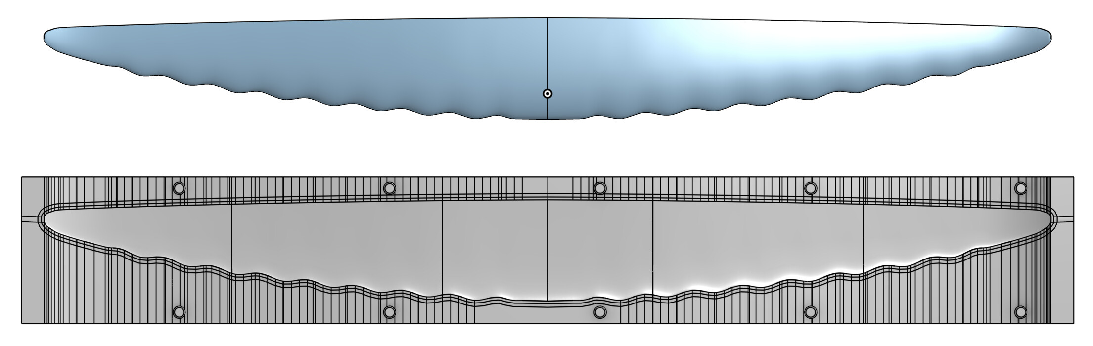
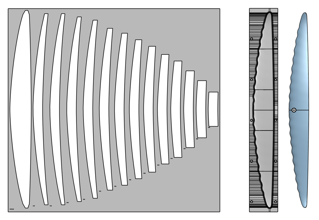
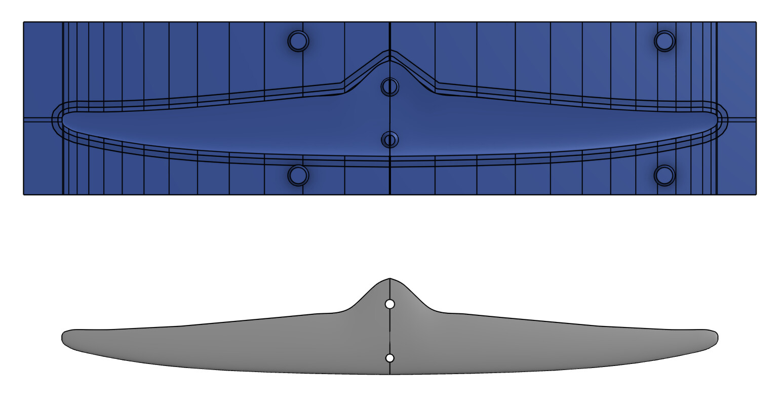
One thing the mold taught: leading-edge bumps that start on the centreline break it; from 5 % out they’re fine. AFS put the mount there anyway, so the tool now refuses 0.
**Parameters.** Ultra 900: Area 900, Aspect ratio 14, NACA 4-digit 2.5 % camber at 40 % (guess), Built-in section data, Root thick 13.1 %, Tip thick 11 %; Superellipse n 1.5, End ratio 0.17, Align line 87 %, no sweep (measured); Drop shape S-curve, Tip drop 24 mm, Drop from 15 %, Drop to 85 % (measured); Winglet Up 25 cm², 25°, Bend radius 200 (measured curl); LE bumps 5 mm high, 53 mm pitch, from 5 to 88 % (measured); Tip cap Rounded + plan 20 mm, 25 %; Min tip 1 mm. U Glide 43: Area 133, Aspect ratio 13.7, NACA 4-digit symmetric (guess), Root thick 10.9 % (their 5 mm), Superellipse n 1.3, End ratio 0.26, Align line 17 %, Sweep aft 13 mm (measured), Root tail 20 mm over 15 % for the mount block, Washout 1° (guess at their twist), Arm 570, Incidence −1. Performance: 85 kg, 13 / 17 / 28 km/h, 3 g. Mold: 2 × 200 g skins, 300 g UD, caps 40 % chord, monolithic core.
Still nothing published on the sections, so those rows stay guesses. If anyone rides an Ultra and can give me a flat-water paddle-up speed, that’s the calibration.
---
### Author:  [@Jb69](https://foil.zone/u/Jb69)
#### Post date: [September 24, 2026, 8:43am UTC](https://foil.zone/t/going-down-a-rabbit-hole-parametric-foil-design-and-printable-molds-in-onshape/27227/8 "2026-09-24T08:43:12Z")
Version 1 is published. Anyone with an Onshape account can add it without copying anything:
1. In a Part Studio, open the custom feature tool (the _Add custom features_ icon at the right of the feature toolbar).
2. Search for **Foil designer** and add it.
3. The six features appear in your toolbar: Foil wing, Foil stabiliser, Foil performance, Foil mast, Foil fuselage, Foil mold. Use them in that order.
Right-click any of the features and choose _Open linked document_ to get to the public document, which has the Feature Studio, an example Part Studio with all six features already placed, and the user guide as a PDF tab.
[image: the custom feature search showing Foil designer, or the six features in the toolbar]
The rest of the package is on GitHub: [GitHub - jb69/Foil-Design-Tool · GitHub](https://github.com/jb69/Foil-Design-Tool)
- the guide as a PDF, readable there without downloading
- **foil-design.zip** (direct download: [https://github.com/jb69/Foil-Design-Tool/raw/main/foil-design.zip](https://github.com/jb69/Foil-Design-Tool/raw/main/foil-design.zip)) with the Feature Studio source, the guide, a table of every dialog field, the AI assistant that reads your console log, two example logs to try it on, and parameter documents for the AFS range: every front wing, stab, mast and fuselage family, measured from their published numbers and renders, so you can model a foil you know as a starting point
What’s in it since the first post, for anyone who skimmed the thread: the mast and fuselage features and their drag in the sweep, the propulsion group for eFoil and foil assist, tabulated sections (Eppler E817, E818, NACA 63-412, Clark Y) and a separate tip section blended along the span, the double taper planform of current production stabs with plan-rounded tips and the tail built into the outline, winglets, leading-edge bumps, the S-curve span drop for gull wings, a core option in the layup (tow, foam, monolithic, or a 3D-printed core generated as a part with dowel keys), and a mold for the foam core itself. All of it was driven by modelling the AFS Silk V2, U Carve, Ultra and U Glide, which is where the earlier posts come from.
Two things to know before trusting a number. Every result is a steady-state estimate for one speed, one weight and flat water, so trust the trend between variants and calibrate the absolute stall speed against a foil you’ve ridden (the guide says how). And the layup, stiffness and mold chapters are theory until someone has built from them. That someone might be me, but if you get there first, a photo of the part and what the tool got wrong is the most useful thing you can post.
Share what you create
Licence is CC BY-NC-SA 4.0. Feedback here, or as issues on the GitHub page.
---
### Author:  [@Jb69](https://foil.zone/u/Jb69)
#### Post date: [September 25, 2026, 12:17am UTC](https://foil.zone/t/going-down-a-rabbit-hole-parametric-foil-design-and-printable-molds-in-onshape/27227/9 "2026-09-25T00:17:11Z")
Version 4 is published, and it is the one to add. Anyone with an Onshape account gets it without copying anything:
1. In a Part Studio, open the custom feature tool (the _Add custom features_ icon at the right of the feature toolbar).
2. Search for **Foil designer** and add it.
3. The six features appear in your toolbar: Foil wing, Foil stabiliser, Foil performance, Foil mast, Foil fuselage, Foil mold. Use them in that order. If you added an earlier version, update it from the same dialog.
Right-click any of the features and choose _Open linked document_ for the public document: the Feature Studio, an example Part Studio with all six features placed, and the user guide as a PDF tab.
[image: the custom feature search showing Foil designer, or the six features in the toolbar]
**New since version 1** , all driven by getting the AFS wings through the molds:
- **Molds close with clamps or in a vacuum bag.** _Closing_ = Vacuum bag rounds the block’s outer edges so the bag survives, vents the pinch-off groove out through the flange at each tip (inside a bag the groove is otherwise a sealed pocket the flash cannot enter), and reports the closing force the atmosphere gives and the pressure on the laminate: about 5.7 kN and 4 bar on a stab mold, 14.5 kN and 1.5 bar on a 950 cm² wing mold at 85 kPa. Overcharge drops to 3 to 5 % with a bag, and the notice checks the groove holds the flash either way.
- **The mast’s plate tray follows the plate as you modelled it.** Fillets, chamfers, another outline or a thicker plate added by hand above the mold are measured off the part and go into the tray; only the bolt pins stay on the mast’s own pattern.
- **A tip section blended along the span** , the way production wings run a cambered root out to a flatter tip, in the geometry, the mold and the performance sweep.
- **The guide has a chapter on where the sections came from** and what matters in water: NACA 4-digit and 6-series, the Eppler hydrofoil sections, Clark Y, with their thickness, camber, zero-lift and moment numbers side by side, and which to use at which speed.
Since the first post, for anyone who skimmed the thread: the mast and fuselage features and their drag in the sweep, the propulsion group for eFoil and foil assist, tabulated sections (Eppler E817, E818, NACA 63-412, Clark Y), the double taper planform of current production stabs with plan-rounded tips and the tail built into the outline, winglets, leading-edge bumps, the S-curve span drop for gull wings, a core option in the layup (tow, foam, monolithic, or a 3D-printed core generated as a part with dowel keys), and a mold for the foam core itself.
The rest of the package is on GitHub: [GitHub - jb69/Foil-Design-Tool · GitHub](https://github.com/jb69/Foil-Design-Tool)
- the guide as a PDF, readable there without downloading
- **foil-design.zip** (direct download: [https://github.com/jb69/Foil-Design-Tool/raw/main/foil-design.zip](https://github.com/jb69/Foil-Design-Tool/raw/main/foil-design.zip)) with the Feature Studio source, the guide, a table of every dialog field, the AI assistant that reads your console log, two example logs to try it on, and parameter documents for the AFS range: every front wing, stab, mast and fuselage family, measured from their published numbers and renders, so you can model a foil you know as a starting point
Two things to know before trusting a number. Every result is a steady-state estimate for one speed, one weight and flat water, so trust the trend between variants and calibrate the absolute stall speed against a foil you’ve ridden (the guide says how). And the layup, stiffness and mold chapters are theory until someone has built from them. That someone might be me, but if you get there first, a photo of the part and what the tool got wrong is the most useful thing you can post.
Licence is CC BY-NC-SA 4.0. Feedback here, or as issues on the GitHub page.
---
### Author:  [@Jb69](https://foil.zone/u/Jb69)
#### Post date: [September 25, 2026, 1:40pm UTC](https://foil.zone/t/going-down-a-rabbit-hole-parametric-foil-design-and-printable-molds-in-onshape/27227/10 "2026-09-25T13:40:51Z")
Something changed this week that I did not see coming when I started this: I am no longer typing into the Feature Studio. I tell Claude (Ai) what I want in plain words and it does it in Onshape.
The repository now has a small server (`onshape_mcp/`, plain Python, nothing to install) that gives the assistant Onshape’s API: it can replace the Feature Studio’s code, set any parameter on any feature, regenerate, and read back every feature’s status and the tool’s own notices and console logs, which version 5 keeps in variables for exactly that purpose. The loop that used to be “paste the build, regenerate, paste the console back” has gone. Two examples from this afternoon, verbatim:
- “fix the wing mold groove, and set the overcharge to 4 %”. It set the groove to 6 x 3.5 mm on the wing mold, 4 % on the stab mold, regenerated, and read back that the groove now holds 42 cm³ against 37 cm³ of flash with no warnings left.
- “the stab mold shows a flat bottom with countersunk holes and the pad on the top mold. the stab is configured the opposite”. It found the cause in the mold code (a pad-under stab was being molded upside down, a workaround from a much earlier build that no longer had a reason), changed it, pushed the new build, regenerated my Part Studio and read the notices to confirm the cones now stand on the top face. A few minutes, and I never opened the code.
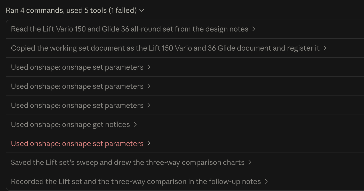
Setup is in `onshape_mcp/README.md`: an Onshape API key in a file outside the repository, the document ids in a config file, and Claude Code picks the server up from the repository’s `.mcp.json`. A free Onshape account can create the API key. You still design the foil; the assistant is the pair of hands, and its two skill packages (the design assistant that reads the sweep, and the developer skill that knows the tool’s code) are in the zip so it knows what it is doing. Two cautions from the same afternoon: it makes mistakes of its own and fixes them when you point at the picture, so read the notice before you believe a change, and run one session at a time on a document, because two sessions pushing builds overwrite each other. You can iterate on a design to find performance gains.
**Version 5 (build 207)** is published as **Foil designer** in Onshape’s custom feature search; update from the same dialog if you have version 4. New since version 4, most of it from asking “what do production foils actually do at the root”:
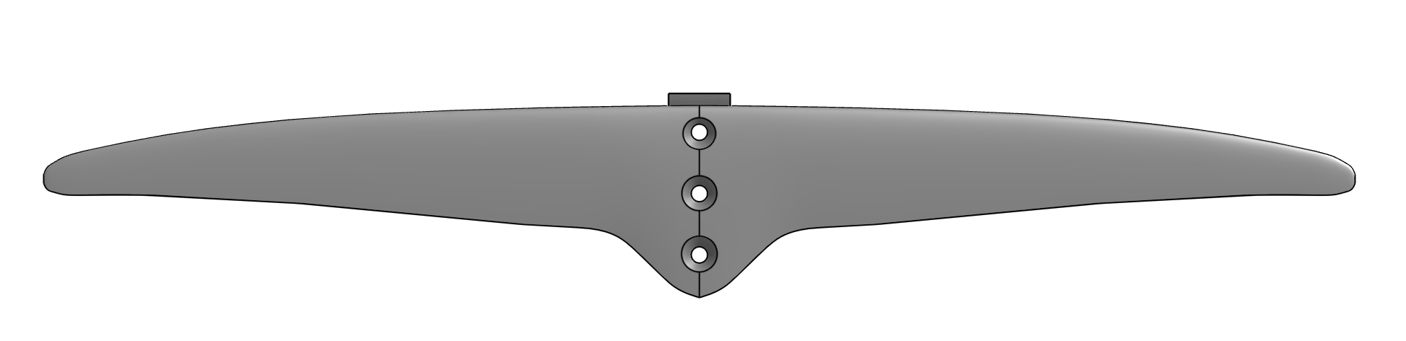
- **Four ways to join the fuselage** , chosen on the wing. The round tube socket and a square socket for a flat bar or tongue, both held by countersunk bolts through the nacelle’s top, the square bore with the rounded corners extruded bar actually has. A flat hub with a pocket, the production layout: a flat-topped hub on the root level with the section’s apex, a recessed pocket open at its square back for the fuselage’s nose, blind holes for bolts down through the fuselage, and the join filleted in a way that cannot fail. And the simplest of all, a flat mount: countersunk bolts straight down through the wing on the centreline onto a flat bar, the home-build layout, which suits a flat-sided section.
- **The mold takes the joint from the part as modelled** , not from the numbers. The socket plug is the bore’s own core, severed from the halves by the plug channel, so a chamfer or any direct edit to the bore shows up in the plug; the countersinks are molded by the half they are cut in; the hub molds with its pocket, fillet and holes as they are.
- **The stab’s mount is the stab’s.** Mount side (top or bottom) stands apart from the pad, because some stabs have none; the pad can be zero high on a flat-sided section, its front ramp can be turned off, and the block that used to sit on the fuselage under the seat is now part of the stab, wrapped round the fuselage’s diameter. The fuselage only cuts its flat seat and taps the holes. A pad-under stab is molded the way round it is designed.
- 
- **Molds have a Detail setting.** _Preview_ builds only the two halves with the cavity, parting, plug and cones, so a studio with molds regenerates in a fraction of the time while the wing and the joint are still moving; _Print_ is the full set with groove, keys, tiles and templates.
- **Printed cores** keep clear of the joint (optional), take two dowels per joint, and the mold reads the mast plate as you modelled it.
Everything is on GitHub, [https://github.com/jb69/Foil-Design-Tool:](https://github.com/jb69/Foil-Design-Tool:) the guide as a PDF, and foil-design.zip (direct download [https://github.com/jb69/Foil-Design-Tool/raw/main/foil-design.zip](https://github.com/jb69/Foil-Design-Tool/raw/main/foil-design.zip)) with the source, the guide, the parameter table, both assistant packages, the Onshape server, and parameter documents for the AFS, Code, AXIS and Lift ranges measured from their published numbers and renders.

Same caveats as before, and they matter more now that it is this easy to make changes: every number is a steady-state estimate, and nobody has laid up a part from these molds yet. If you build one, what the tool got wrong is the most useful post in this thread.
---
### Author:  [@Jb69](https://foil.zone/u/Jb69)
#### Post date: [September 26, 2026, 12:28am UTC](https://foil.zone/t/going-down-a-rabbit-hole-parametric-foil-design-and-printable-molds-in-onshape/27227/11 "2026-09-26T00:28:45Z")
Tuning a wing without regenerating it: the Silk-class 1050 set, worked through
Follow-up to the AFS posts above. This time not a new wing but the same one tuned, and the interesting part is how: the tool’s own maths, run outside Onshape, with Onshape used once at the end to check. Standard caveat applies: steady-state estimates, wing and stab only, from someone who has not built one yet.

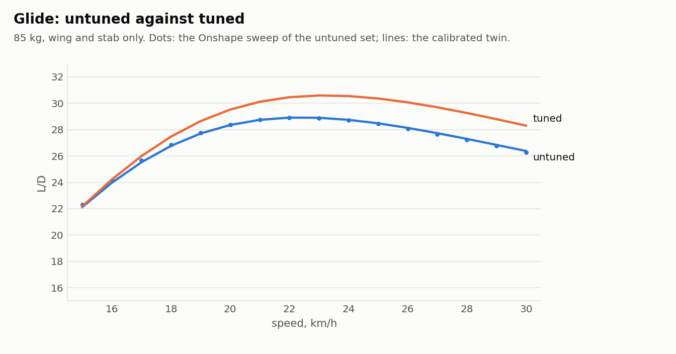
**The starting point.** The Silk V2 1050 outline and the U Surf 135 outline as measured off AFS’s renders in the earlier posts, with the things AFS don’t publish (sections, angles, thicknesses) at my first guesses: NACA 3 % camber, 12 % thick at the root, 10 at the tip, a 1.5 % tip section blended in from 40 % span, the stab at −1.5°. At 85 kg all-up that gave a glide of 28.4 at 20 km/h, take-off at 73 % of the section’s CL max at 15 km/h, and a static margin of 16 % of the mean chord at take-off, which is a lively but stable surf foil.
**How the tuning was done.** The performance feature is lifting-line theory for the wing and stab, trim about the neutral point, and profile drag from a section polar (the built-in NACA polars are fits to XFoil runs at two Reynolds numbers), with a tip section entering as a station-by-station change in zero-lift angle and CL max along the span. All of that is arithmetic, so I have a Python copy of it that runs a sweep in a fraction of a second. I calibrated the copy against the tool’s Onshape sweep of the untuned set, two scale factors on drag and one on stall loading, and after that it matches Onshape within 1 % on drag at 15, 20 and 30 km/h, on L/D at 22, on trim CG and on static margin. Then every lever one at a time, then a grid over the ones that helped, keeping both outlines fixed and throwing out anything that put take-off past 80 % of CL max or the static margin under 12 % at 15 km/h. That is about a thousand sweeps; Onshape would have taken a week of regenerations.

**What moved and why.** Four things, all small, all in the same direction.
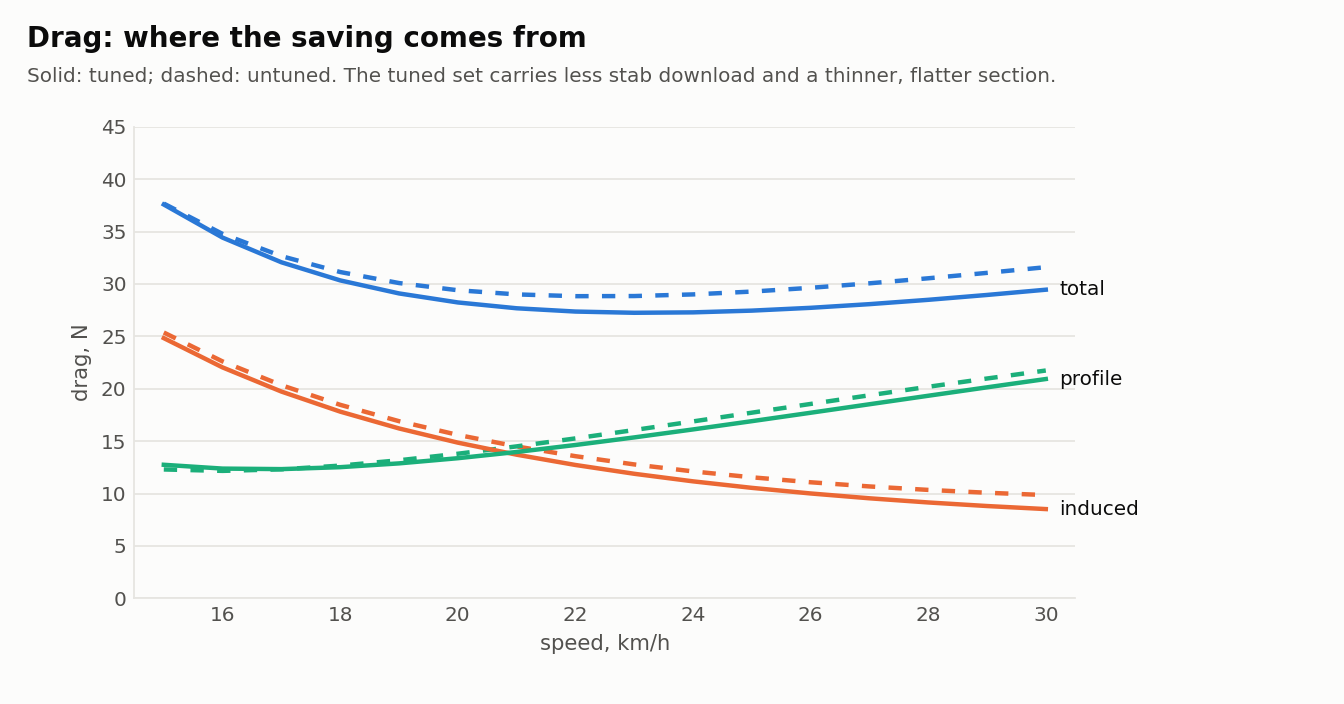
Root camber 3 to 2.5 %: half the gain. At 20 km/h this wing flies at a lift coefficient around 0.5, and a 3 % section’s drag bucket sits above that; 2.5 % puts the bucket where the wing actually lives. Below 2.5 the take-off loading starts climbing.
Stab incidence −1.5 to −1.0: a third of the gain. The stab was carrying download from 18 km/h up, which is drag twice over (the stab’s own, and the wing making extra lift to cancel it). Half a degree less and the stab is lifting a little at take-off and pushing down less at speed. The price is static margin, 16 to 12 %, which is why it stopped at −1.0: −0.5 was worth another 0.8 of glide and took the margin to 10.
Section 12/10 to 11/8 % thick: the rest. Less form drag, nothing else changes, and the caps only need 0.7 mm at 3 g.
Tip section 1.5 to 1.0 % camber, still from 40 %: no glide at all, and that is the point of the next paragraph.
**The tip profile, properly this time.** I had put the tip section in because production wings have one and had not asked what it did. Answer: it is not a glide lever. Across tip camber from 0 to 2 % and blend starts from 30 to 60 %, glide moves by half a point at most. What it controls is where the stall starts. With the root section run out to the tip the first section to reach its CL max is at 76 % of the half span, tip first, which is the stall you don’t want. A tip 1.5 % flatter than the root moves it to 68 % for half a point of glide; a symmetric tip makes it root-first at 52 % for another half point and another point of static margin, because unloading the tips moves the lift centroid inboard. Washout does the same job for less glide but costs two points of margin on a short fuselage, so on this arm the tip section is the better tool and on a long one washout would be.
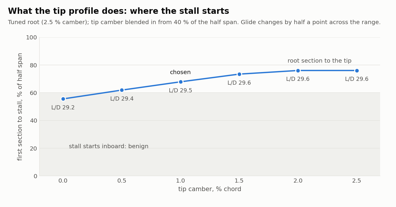
**Outcome.** Glide 28.4 to 29.5 at 20 km/h, best 30.5 at 22 to 24, drag down 4 %, take-off 73 to 75 % of CL max, first stall from 76 to 68 % span, static margin 16 to 12 %, and the stance walk from 58 to 42 mm between take-off and 30 km/h. Small numbers, but they are the difference between a good set and the most this outline gives inside those limits, and the method is what I wanted to show: the tool’s maths tune the design, and Onshape is the step that makes the physical thing.
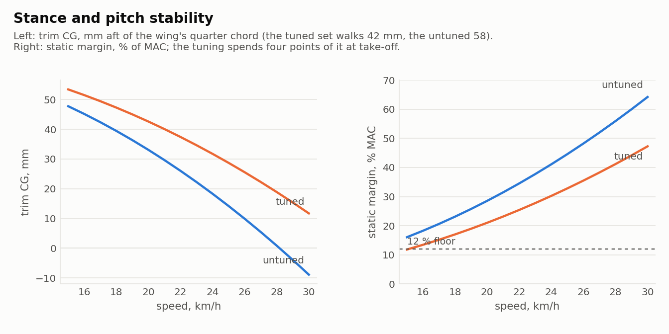
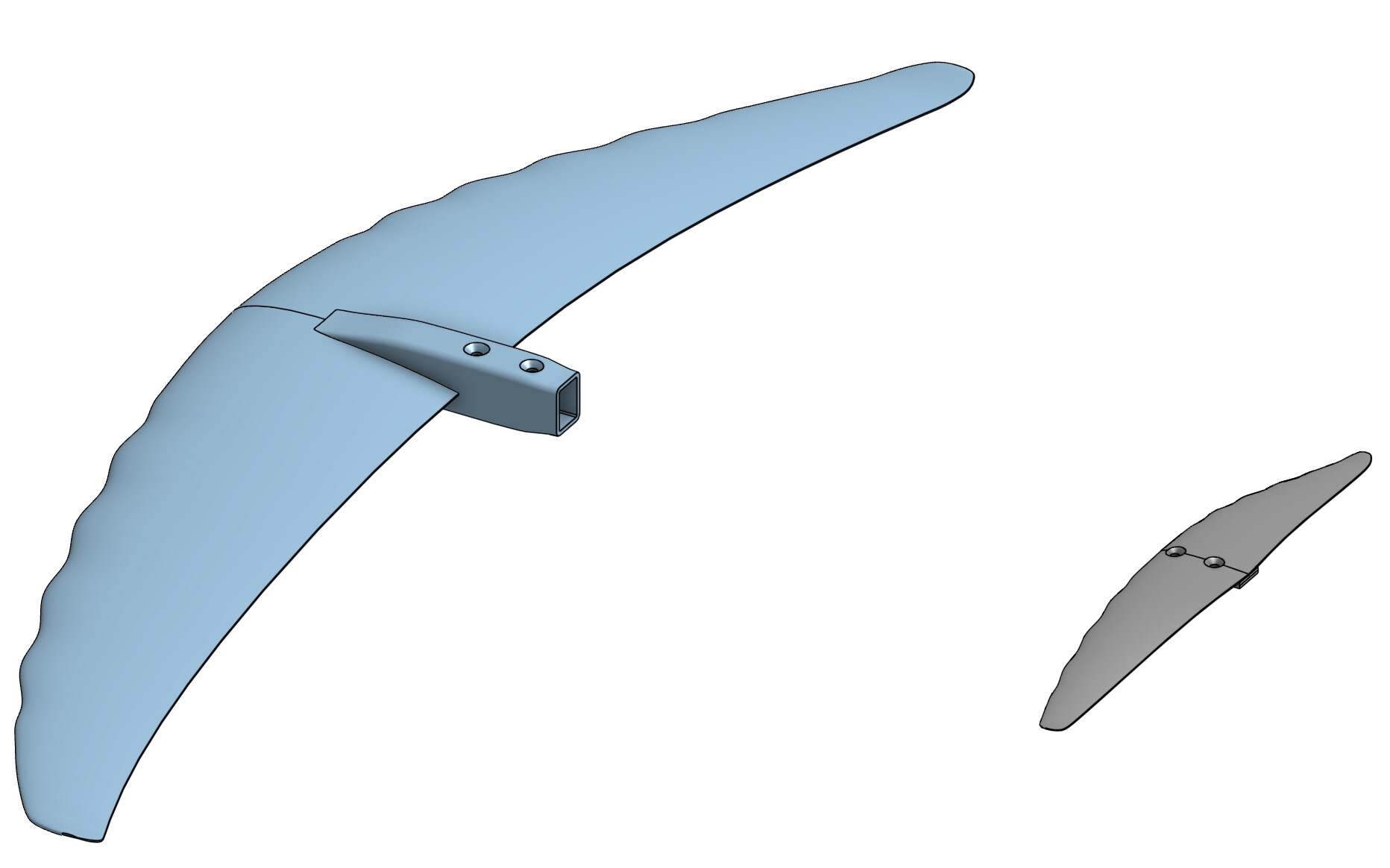
**What it can’t see.** A hand-finished section’s real CL max (quote take-off as 14 to 15 km/h, not the polar’s 12.8), the bar and mast drag (add 10 to 15 N), and the Onshape checks that are still to run: the cap thickness at the thinner root and the mold’s parting on the new tip section. The full parameter tables are in the design notes; the twin and the charts are a couple of Python scripts if anyone wants to try the same on their own wing.
---
### Author:  [@Jan12](https://foil.zone/u/Jan12)
#### Post date: [September 26, 2026, 9:37am UTC](https://foil.zone/t/going-down-a-rabbit-hole-parametric-foil-design-and-printable-molds-in-onshape/27227/12 "2026-09-26T09:37:48Z")
Amazing.
Its too much to process really.
I have a few notes that I find odd.
As mentioned before your takeoff speed is unrealisticly low imo.
Are you sure you are not missing something?
I remember when I was still building foils, I went down a much smaller rabbit hole (XFLR5), but I had trouble in filling the correct base parameters, you completely seem to ignore.
For example setting the right NCRIT value changed the results a lot. But there was no real feedback on what the right value for us actually is. Best input I got there was from Tom Speer (rip) saying its likely between 0 and 1.
Reducing stab incidence always reduces drag, just as using a small stab. Not sure that is optimization or you would end up with no stab.
Incidence of frontwing should not matter at all, unless you add in fuselage drag. So having stab and wing incidence seperate is odd. You generally just consider the delta.
So most of what you did is just put in a less draggy stab and a less lifty frontwing.
Both will reduce drag.
---
### Author:  [@Jb69](https://foil.zone/u/Jb69)
#### Post date: [September 26, 2026, 2:49pm UTC](https://foil.zone/t/going-down-a-rabbit-hole-parametric-foil-design-and-printable-molds-in-onshape/27227/13 "2026-09-26T14:49:08Z")
Thanks Jan, all fair, and a couple of them hit things I should have said more clearly.
**Take-off speed.** Agreed, it reads low, and it will keep reading low. The number is the speed at which the most loaded bit of the wing reaches its section’s CL max in dead steady flight, flat water, a rider who doesn’t move. Nobody takes off there. It’s useful for comparing one variant with the next, not as a speed to quote, and I should have led with the take-off loading rather than a km/h figure.
**Ncrit.** You’re right that it matters, and I’ve now rerun it. The built-in polars are XFoil at Ncrit 9, the wind-tunnel default. What I could find of Tom Speer’s in writing is “3 or even lower” in 2004, and “1\
### Author:  [@Jan12](https://foil.zone/u/Jan12)
#### Post date: [September 26, 2026, 3:31pm UTC](https://foil.zone/t/going-down-a-rabbit-hole-parametric-foil-design-and-printable-molds-in-onshape/27227/14 "2026-09-26T15:31:18Z")
> [@Jb69](#):
>
> It isn’t a claim that AFS got anything wrong, and it’s how I’d take my own wing from a sketch to something worth building.
Nothing wrong with that.
Just observations from my personal builds I did.
The results from XFLR5 always favored really thin optimized airfoils, that are also often used in RC planes.
Unfortunately when trying them in water they have always been not so great in reality. There seems to be a disconnect between the simulation and how it turns out in water.
My assumption has been its either the turbulence we face or the fact it’s less static movement compared to planes.
End result was that more forgiving thicker sections in general performed much better.
---
### Author:  [@Jb69](https://foil.zone/u/Jb69)
#### Post date: [September 27, 2026, 1:10am UTC](https://foil.zone/t/going-down-a-rabbit-hole-parametric-foil-design-and-printable-molds-in-onshape/27227/15 "2026-09-27T01:10:03Z")
Thanks Jan. I’ve come to look forward to these. Straight observations from someone who has built and ridden the results are worth more to this thread than anything the model says, and this one lands right on the tuning I just posted, which thinned the Silk’s section from 12/10 % to 11/8 %.
So I ran the section your way: NACA 2.5 % camber at four thicknesses, at the Silk’s take-off Reynolds number (0.45 M), at Ncrit 9 (what XFLR5 defaults to) and at Ncrit 1 (Speer’s water end), in NeuralFoil as before.
| Thickness | Drag at CL 0.5 (cruise) | Drag at CL 1.0 (pumping, take-off) | CL max, at | Lift lost 3° past CL max |
| --- | --- | --- | --- | --- |
| **Ncrit 9** | | | | |
| 8 % | 0.0061 | 0.0164 | 1.22 at 10.8° | 25 % |
| 10 % | 0.0066 | 0.0136 | 1.32 at 14.2° | 11 % |
| 12 % | 0.0073 | 0.0118 | 1.34 at 15.5° | 3 % |
| 14 % | 0.0080 | 0.0112 | 1.34 at 15.8° | 2 % |
| **Ncrit 1** | | | | |
| 8 % | 0.0092 | 0.0152 | 1.38 at 13.3° | 9 % |
| 10 % | 0.0099 | 0.0150 | 1.41 at 14.9° | 6 % |
| 12 % | 0.0105 | 0.0151 | 1.40 at 15.6° | 5 % |
| 14 % | 0.0110 | 0.0157 | 1.37 at 16.2° | 4 % |
Section drag coefficients. NeuralFoil is least sure of the 8 % section at Ncrit 9 (confidence 0.65 against 0.9 or more for the rest), so read that row as the trend.
I think that table is your experience in numbers, for three reasons:
- **A steady sweep only asks about one point.** The thin section wins at cruise lift and nowhere else. At CL 1.0 the 8 % section has 40 % more drag than the 12 %. Its stall comes 5° sooner and takes a quarter of the lift with it, where the 12 % hardly notices. My tuning scored the mean glide from 18 to 24 km/h, where the wing sits at CL 0.35 to 0.6. That’s exactly the band where thin looks best. A foil that’s pumped, carved and pushed around by the wave’s orbital flow spends a lot of its time outside that band. So I’d put your second guess, the non-static movement, first.
- **XFLR5 at Ncrit 9 rewards a laminar run that water doesn’t give.** At Ncrit 1 the thin section’s cruise advantage shrinks, and the sharp stall softens too. But the model still says thin is cheaper at cruise, and that’s the number the optimiser chases. The thin RC sections are shaped to get the most out of a long laminar run and a controlled bubble, so they lose the most when neither is there.
- **At speed, cavitation, and it runs the same way.** Water doesn’t compress; at these speeds neither does air, so compressibility plays no part for either a model plane or a foil. But water boils when the local pressure falls to its vapour pressure, and a thin section is the one that gets there first. I ran the same four sections through a panel method for the peak suction on the leading edge. Cavitation starts when that suction exceeds the pressure there is to spare, and at 0.5 m depth that works out to:
| Thickness | Peak suction at CL 0.5 | Cavitates from | Peak suction at CL 1.0 | Cavitates from |
| --- | --- | --- | --- | --- |
| 8 % | −0.64 | 64 km/h | −3.82 | 26 km/h |
| 10 % | −0.71 | 61 km/h | −2.75 | 31 km/h |
| 12 % | −0.78 | 58 km/h | −2.22 | 34 km/h |
| 14 % | −0.86 | 55 km/h | −1.95 | 37 km/h |
In level cruise nothing on a surf foil comes close. But a 3 g carve at 26 km/h asks for a CL of about 0.9 from the wing, more on its most loaded sections, and that is right where the 8 % section’s leading edge starts to boil while the 12 % has 8 km/h in hand. Add ventilation, which the model doesn’t do and which starts from the same suction peak, and the thin section is again the one that lets go first. It’s inviscid, 2D and steady, so read the speeds as a ranking, not a prediction.
The production wings agree with you, too. Every AFS front wing I measured is 11 to 13 % thick whatever its aspect ratio. So I’m not going to tell anyone 11/8 is better on the strength of a steady-state score. The next change to the tuning is to score the foil across an angle-of-attack swing around trim, not only at the trimmed point, and to add a limit on how abruptly the most loaded section stalls. That should bring back the thickness the steady score takes away. I’ll post what it picks.
Can I ask what you tried, if you remember? Which thin sections, how thick the ones that worked better were, and whether “not so great” meant take-off, stall behaviour in turns, or glide. That would let me set the swing and the stall limit from something real rather than my guess.
---
### Author:  [@Jan12](https://foil.zone/u/Jan12)
#### Post date: [September 27, 2026, 8:41am UTC](https://foil.zone/t/going-down-a-rabbit-hole-parametric-foil-design-and-printable-molds-in-onshape/27227/16 "2026-09-27T08:41:00Z")
MH18 was always the winner in simulation with higher NCRIT. Worked on water but not too great.
H105 wins with low NCRIT, worked well in water, but really too much pitch moment. So had to compensate with larger stab.
MRC16 was the one that performed best overall in water.
But this was beginning 2021 so foils looked quite a bit different to now. Once the production foils got good enough I did not bother building any more.
---
### Author:  [@Jb69](https://foil.zone/u/Jb69)
#### Post date: [September 27, 2026, 9:59am UTC](https://foil.zone/t/going-down-a-rabbit-hole-parametric-foil-design-and-printable-molds-in-onshape/27227/17 "2026-09-27T09:59:32Z")
Thanks Jan, that’s exactly what I was hoping for: three named sections and what each did on the water.
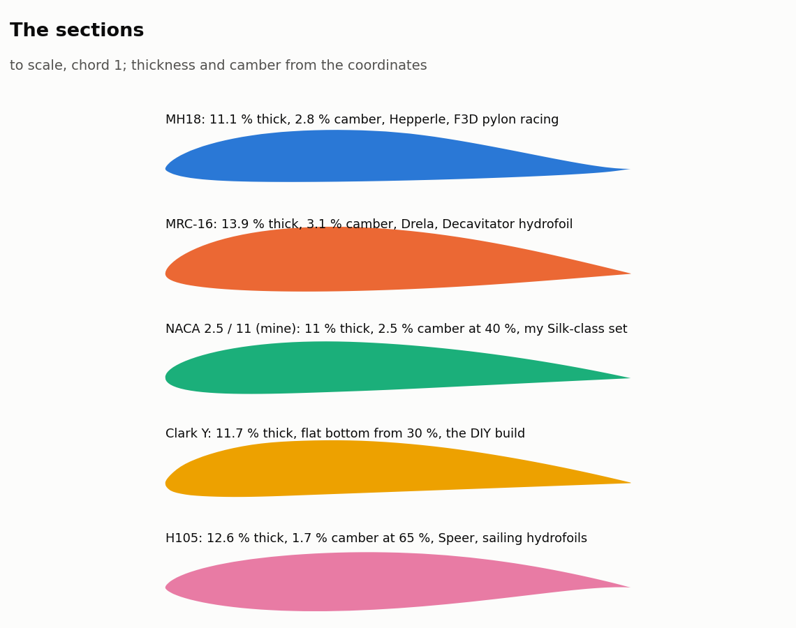
I ran all three the same way as the thickness table, with polars from NeuralFoil at the Silk’s take-off Reynolds number (0.45 M), at Ncrit 9 and Ncrit 1, and the tool’s two sections alongside: the NACA 2.5 % / 11 % my Silk-class set uses (the AFS outline, but its own sections, angles and thicknesses, so its own character) and the Clark Y. As a check I set them against the XFoil polars airfoiltools publishes for both at Re 0.5 M and Ncrit 9: before the stall they agree within about 5 % on drag, CL max and moment. The H105 isn’t in the usual databases; its coordinates are the copy shared on [boatdesign.net](http://boatdesign.net), and no XFoil polar of it is published, so it rests on NeuralFoil alone. I added one column this time for your H105 point: the pitching moment.
| Section | Drag at CL 0.5 (cruise) | Drag at CL 1.0 (pumping, take-off) | Mean drag, CL 0.2 to 1.1 | CL max | Lift lost 3° past CL max | Cm at CL 0.5 |
| --- | --- | --- | --- | --- | --- | --- |
| **Ncrit 9** | | | | | | |
| MH18, 11.1 % | 0.0078 | 0.0115 | 0.0100 | 1.18 | 4 %\* | −0.046 |
| MRC-16, 13.9 % | 0.0079 | **0.0101** | 0.0086 | 1.37 | **2 %** | −0.066 |
| NACA 2.5 % / 11 % | 0.0069 | 0.0126 | 0.0087 | 1.33 | 5 % | −0.075 |
| Clark Y, 11.7 % | 0.0070 | 0.0105 | 0.0084 | 1.43 | 4 % | −0.089 |
| H105, 12.6 % | 0.0075 | 0.0221 | 0.0122 | 1.16\* | 24 %\* | −0.077 |
| **Ncrit 1** | | | | | | |
| MH18 | **0.0090** | 0.0167 | 0.0117 | 1.26 | 6 % | −0.021 |
| MRC-16 | 0.0100 | 0.0136 | 0.0114 | 1.39 | 3 % | −0.059 |
| NACA 2.5 % / 11 % | 0.0102 | 0.0149 | 0.0119 | 1.40 | 6 % | −0.055 |
| Clark Y | 0.0110 | 0.0129 | 0.0115 | 1.47 | 5 % | −0.076 |
| H105 | 0.0105 | 0.0178 | 0.0129 | 1.29 | 9 % | −0.064 |
And the same panel method as last time for the leading-edge suction, as the speed at which each would start to cavitate at 0.5 m depth:
| Section | At CL 0.5 | At CL 1.0 |
| --- | --- | --- |
| MH18 | 55 km/h | **25 km/h** |
| MRC-16 | 56 km/h | **42 km/h** |
| NACA 2.5 % / 11 % | 59 km/h | 33 km/h |
| Clark Y | 56 km/h | 40 km/h |
| H105 | 64 km/h | 26 km/h |
\* NeuralFoil is least sure of the MH18 and the H105 at Ncrit 9 (confidence 0.75 and 0.68, against 0.97 or more for the rest) and can’t follow the MH18 past its peak at all, so that figure is XFoil’s; the H105’s Ncrit 9 stall figures are its least certain numbers here, and at Ncrit 1 it is sure of them. XFoil’s MH18 polar also shows what the peak looks like: the lift stops climbing at about 1.05 from 8°, and the drag doubles between CL 0.9 and 1.1.
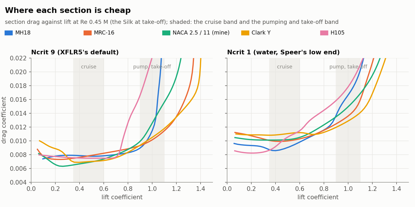
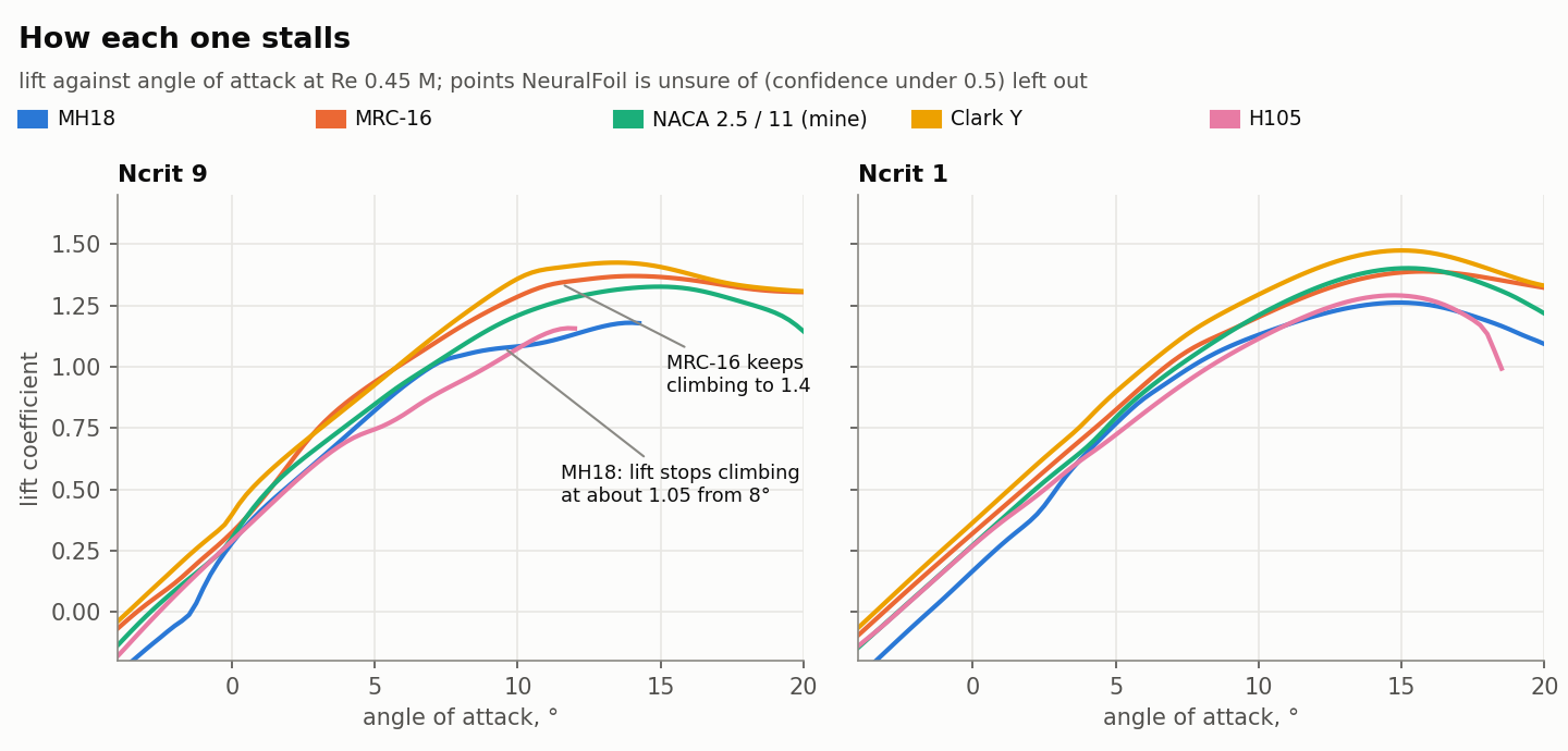
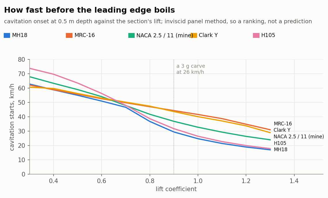
I think your three sections tell the whole story of the last few posts:
- **At the cruise point the model can’t tell them apart.** At CL 0.5 all four are within 15 % of each other at Ncrit 9 and 22 % at Ncrit 1, and at Ncrit 1 the MH18 is actually the cheapest. I put each section on my Silk-class set in the twin (the tool’s lifting line and trim, with these polars, everything but the wing’s section left as tuned) and scored it the way my tuning did, mean glide from 18 to 24 km/h, steady and trimmed. At Ncrit 9 the H105 and the thin NACA come first, the MH18 within 2 %, and the MRC-16 7 % behind, because its low-drag bucket sits at higher lift than that wing cruises at. At Ncrit 1 the four are within 4 % of each other at cruise. Then I ran the model where a foil is actually ridden hard, not just at cruise: take-off at 14 km/h, a pump stroke (1.5 g at 14 km/h) and a 3 g carve at 26. There the MRC-16 has bought a stall a full km/h lower, the lowest take-off loading, a pump stroke that only just stalls where the MH18 is 27 % into it, three points more static margin, and a carve that stays clear of cavitation to 45 km/h against 30 for the MH18. That is your XFLR5 experience reproduced: a steady cruise score ranks the section that was best on the water last, and the things it was best at aren’t in the score.
| Wing section, whole foil at 85 kg, Ncrit 1 | Mean L/D 18-24 | L/D at 30 | Stall | Take-off at 14 km/h | Pump stroke, 1.5 g at 14 | 3 g carve at 26 km/h | Carve cavitates from |
| --- | --- | --- | --- | --- | --- | --- | --- |
| NACA 2.5 % / 11 % (mine) | 23.6 | 19.5 | 12.6 km/h | 79 % of CL max | 118 %: stalls | L/D 23.3 at 65 % | 37 km/h |
| MRC-16 | 23.1 | 17.6 | **12.0** | **73 %** | **107 %** | 21.7 at **61 %** | **45 km/h** |
| MH18 | **24.0** | 19.3 | 13.0 | 86 % | 127 %: stalls | 21.7 at 70 % | 30 km/h |
| H105 | 23.9 | 18.6 | 12.4 | 79 % | 116 %: stalls | 21.4 at 64 % | 32 km/h |
| Clark Y | 22.4 | 16.9 | 11.4 | 66 % | 97 %: holds | 21.6 at 55 % | 44 km/h |
At Ncrit 9 the same sets read mean L/D 29.6 / 27.6 / 29.1 / 29.9 / 27.5 and pump-stroke loadings 129 / 109 / 137 / 129 / 105 %: the MH18’s lead is a cruise lead at the tunnel’s Ncrit, and its pump stroke is the deepest into the stall at either.
Wing and stab only; stall and loading from the polar’s CL max, so all a little optimistic for a hand finish; “stalls” means the most loaded station is past its section’s CL max in that stroke. The stab is the one I tuned for the NACA wing, so each section is a fair swap, not a retune; the MRC-16 wants a little less camber-equivalent in the trim and would give some of the margin back as glide.
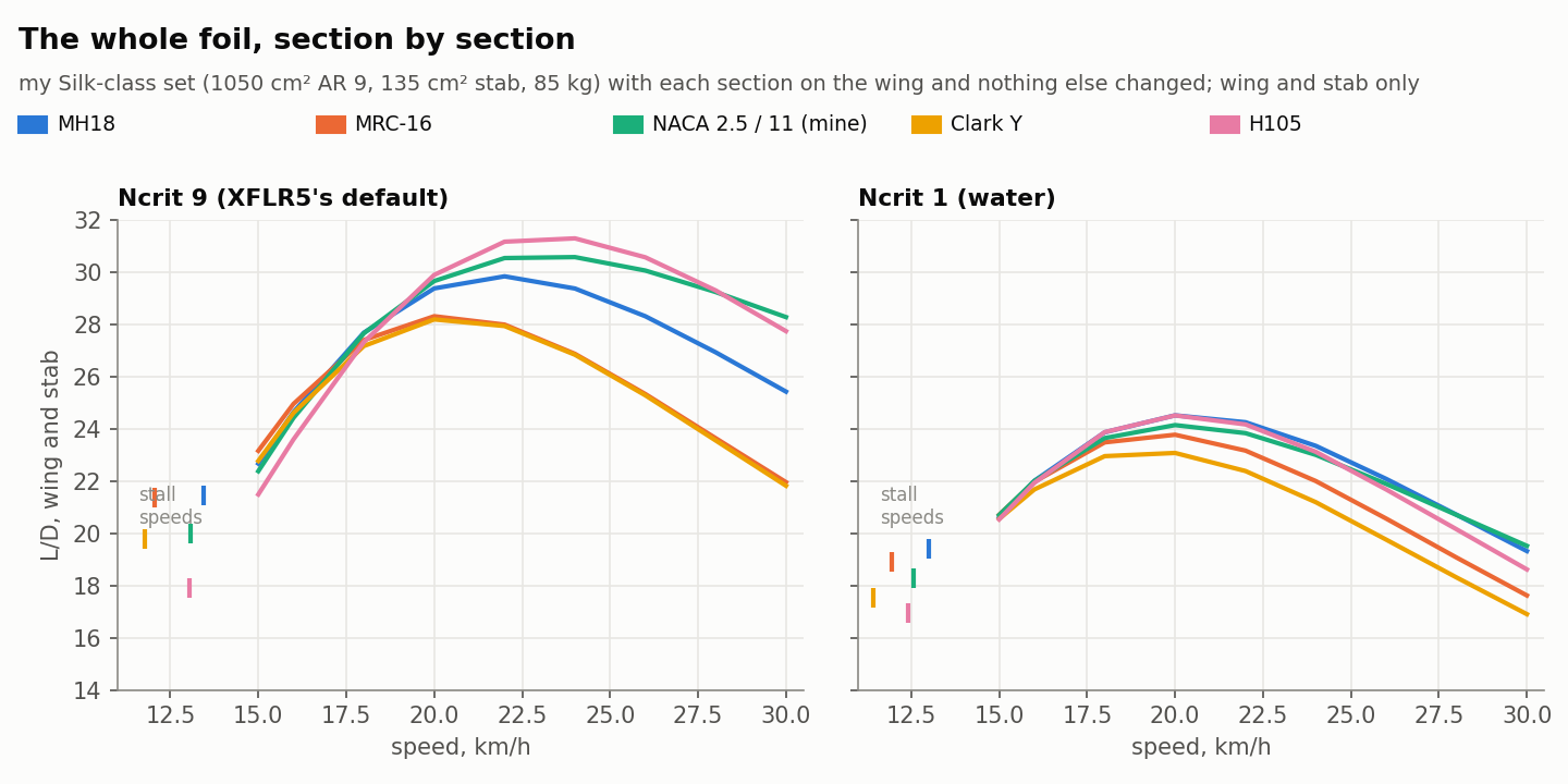
- **Away from cruise the ranking is yours.** The H105 sits between: at Ncrit 1 its stall is softer than the MH18’s and its drag at CL 1.0 lower, but its leading edge boils almost as early in a carve. At CL 1.0 the MH18 has the most drag of the four at Ncrit 1 (at Ncrit 9 only the thin NACA, the 11 % section my Silk-class set ended up with, is worse, which is your thickness point again), its lift stops climbing at about CL 1.05 while the drag doubles, and its leading-edge suction is nearly three times the MRC-16’s: in a hard carve it starts to cavitate, and ventilation starts from the same suction peak, at about 25 km/h against 42. The MRC-16 has the least drag at CL 1.0 at Ncrit 9 and close to it at Ncrit 1, the gentlest stall, and the most cavitation margin, at 13.9 % thick. Mark Drela drew it for the Decavitator, the human-powered hydrofoil boat, so it was designed for water from the start. It’s the forgiving thicker section you described, in numbers.
- **The pitching moment is real and a section table hides it.** Clark Y has the biggest moment here, −0.076 to −0.089, and it’s why a Clark Y foil like the classic DIY builds carries a big stab. A section with more nose-down moment needs more download from the stab or a bigger stab to trim, and both cost drag that doesn’t show up in the section’s own polar. The tool does put the wing’s moment into its trim, so that part of your H105 experience it should see, and here it doesn’t: my H105 polar gives Cm −0.08, a third more than the MH18’s but no more than the NACA’s, and on the Silk-class set its stab load and margin come out the same as the NACA’s. So either the H105 I have (the coordinates shared on [boatdesign.net](http://boatdesign.net)) isn’t the one you ran, or its moment is higher in XFLR5 than NeuralFoil makes it. What did XFLR5 give you for its Cm?
So the change to the tuning I mentioned gets a check it can be held to. It will score each set across CL 0.2 to 1.1 and at CL 1.0, not just the trimmed cruise point, with a limit on stall abruptness and on the cavitation speed in a 3 g carve, and the moment going through the trim as it already does. If that scoring doesn’t put the MRC-16 ahead of the MH18, it’s wrong.
I’ll also add them to the tool as section options, with a note on where each one fits, so anyone can try them on their own wing rather than take my word for it. Roughly:
| Section | Where it fits | Watch for |
| --- | --- | --- |
| MRC-16 | anything pumped, carved or taken off slowly: surf, wing, downwind, pump, eFoil | the all-rounder of these four; thick enough to carry the spar at the root |
| MH18 | fast, flat-water wings that live at low lift: kite and wind racing, top-speed runs | tops out at CL 1.05 to 1.1 and cavitates first in a hard turn; not a pumping section |
| H105 | low-speed, high-lift take-off, the way Speer drew it | a big nose-down moment, so a bigger stab (to be confirmed once I have it) |
| Clark Y | home builds that bolt a flat bottom to a bar | the most lift and the biggest moment here, so a big stab; costs drag at speed in real water |
And if you remember how much bigger the H105’s stab had to be, that would give me a real number for what the pitching moment costs.
---
### Author:  [@Jan12](https://foil.zone/u/Jan12)
#### Post date: [September 27, 2026, 11:42am UTC](https://foil.zone/t/going-down-a-rabbit-hole-parametric-foil-design-and-printable-molds-in-onshape/27227/18 "2026-09-27T11:42:09Z")
> [@Jb69](#):
>
> - So either the H105 I have (the coordinates shared on [boatdesign.net](http://boatdesign.net)) isn’t the one you ran
Did not see that in simulation, but in use.
So its possible it was another attribute of that specific wing and not the section.
Also I think that section was pretty hard to replicate in a real world build, with its odd camber line.
---
### Author:  [@Jb69](https://foil.zone/u/Jb69)
#### Post date: [September 30, 2026, 12:57am UTC](https://foil.zone/t/going-down-a-rabbit-hole-parametric-foil-design-and-printable-molds-in-onshape/27227/19 "2026-09-30T00:57:32Z")
**How the tool works, and how much of it is AI**
Nobody has asked, but since I say I use Claude for most of this, I think it’s worth putting down what is actually behind the numbers the tool gives, and how much of it is AI. Here is the honest version.
**The tool builds the physical part from parameters.** The Foil Design Tool is a set of FeatureScript features in Onshape. You fill in a dialog (area, aspect ratio, section, camber, thickness, sweep, tip drop, incidence, and so on) and it builds the real 3D geometry: the wing, the stab, the mast, the fuselage, and the printable molds to make them in. Change a parameter and the part regenerates. The prop generator in the other thread works the same way for blades and hubs.
**It runs the maths on that exact geometry.** The same features run a speed sweep on the part they just built: drag by part, L/D, trim, stability margin, stall speed, root loads, cavitation number, and warnings. So the part you can print a mold for and the numbers for that part are one thing, not two.
**The maths is old and open.** Lifting-line theory for the wing and stab. Section polars fitted to XFoil runs for profile drag and stall, shifted to a low Ncrit for water after Jan’s point in post 12 (that shift comes from NeuralFoil, a neural network trained on XFoil, the one bit of machine learning inside the physics). Standard skin-friction and form-factor formulas for the mast, pod and fuselage. Nothing in it is a guess by an AI; the same inputs give the same numbers every time.
**Where the results come out.** Every feature writes a notice under itself in the feature list (one line: what was built, what it does, any warnings) and a report on the console (every input on one line, then the sweep as a table). Plain text, made to be copied. The download includes an assistant skill for Claude, ChatGPT and the others: paste the notice and the console report, and it explains the numbers, checks them against target ranges, and recommends a few changes in the dialog’s own labels, with the expected effect and the cost. That is how the tool feeds back into the AI, and anyone can do it with the public tool.
**Thousands of variations.** There is also a Python copy of each feature (a “twin”), which agrees with the tool within 1 % and runs in seconds. That is what lets a study test thousands of combinations rather than one at a time. The last one, for a rider building a racing eFoil, ran about 9,000 wing and stab sets: area, aspect ratio, camber, thickness, stab size, stab angle. Each was trimmed at every speed, scored at the race speed, and thrown out if it broke a limit (stance shift, stability margin, a stab working too hard, a root a solid carbon section can’t carry at 3 g). What is left is a curve of the least drag at every lift-off speed, and the winner is its knee. The rules of “winning” are mine; change them and it finds a different winner. The check that made me trust the curve: the makers’ own race wings, run through the same twin at their published sizes, land on that curve at their own lift-off speeds. Only the winner goes into Onshape, once, to confirm.
**Where the makers’ numbers come from.** Published spec tables (area, span, aspect ratio; some publish chord and volume too). Outlines measured from the makers’ plan-view renders, scaled to the published span and fitted with the tool’s own chord shapes, which land within a few percent of the published chord and area. Rear renders for anhedral where a maker has them. Designers’ videos and podcasts, transcribed, for what they say about camber and tips. Retailer pages and magazine tests to fill gaps. Sections, camber and twist are never published, so for any production wing they are suggestions, marked as such. Every number is tagged published, measured or assumed.
**So how much is AI?** The methods: none, they are textbook. The code: most of it was written by Claude from my specifications, and I test it in Onshape and publish it. The section data: XFoil fits, plus NeuralFoil for the water correction. Running the searches and drafting the write-ups: Claude. Reading the makers’ sites, videos and riders’ logs: Claude does the reading and the measuring, I check what it pulls. What to study, the limits, what to believe and what to post: me. Its mistakes are judgement mistakes, not arithmetic ones, and it makes them: in that last study it first compared the race wing with a surf wing, guessed the rider’s current wing wrong, and drew blunt tips until I put it next to real race wings. That is why I check, and why what you report from the water matters more than the model. Jan’s section results are now a test the model has to pass.
**What to trust.** Anything from a log or a measurement, most. Wing against wing, stab against stab, as ranking, next. The absolute km/h or Wh/km for a change, least: the tool’s energy reads low against a real rig, and nobody has measured foil drag on the water. A before-and-after log is the check the model cannot do for itself, and I would rather have one of those than another thousand runs.
---
### Author:  [@Bzhwindtalker](https://foil.zone/u/Bzhwindtalker)
#### Post date: [October 4, 2026, 8:58am UTC](https://foil.zone/t/going-down-a-rabbit-hole-parametric-foil-design-and-printable-molds-in-onshape/27227/20 "2026-10-04T08:58:39Z")
Lots of info, as usually with ai- assisted workflows, its a lot to process even for the project leader!
Not sure I will use the project myself, too much work to get a good real world produced result imo for foils, but following with interest!
It seems you are experimenting with a lot of variants of the fuse-wing connection, that is something that has not been fully solved yet in foiling and still causing issues for most brands, on bigger (\>1200cm2) foils. Rigidity, lack of play, release ability and resistance to fatigue all come into play.
Is there a connection type ypu are leaning towards?
[Next page](https://foil.zone/t/going-down-a-rabbit-hole-parametric-foil-design-and-printable-molds-in-onshape/27227.md?page=2)