Hi everyone, does anyone know how to resolve the Bremote E4 error?
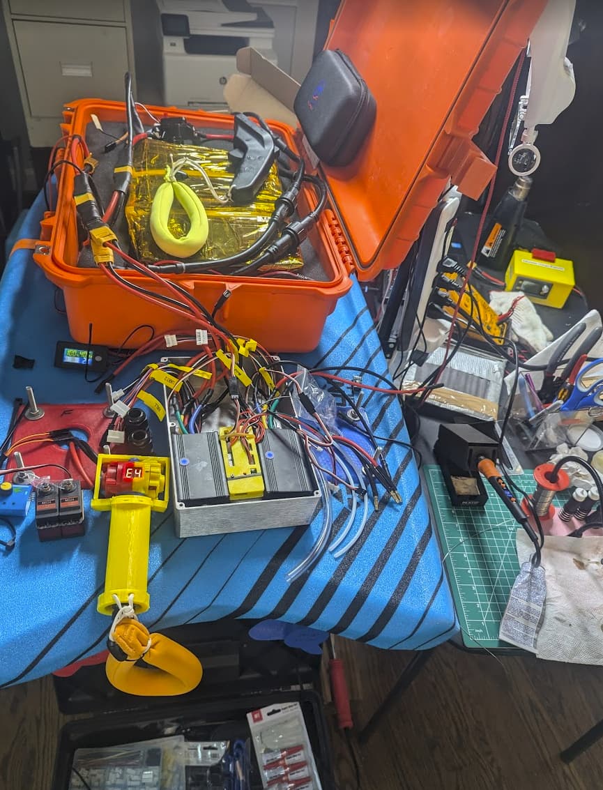
I’ve finally completed my build using the Bremote Long Range kit designed by my brilliant virtual friend @ludwig_bre . Everything is working except for one issue: my connection is sporadic, and I keep getting the E4 error code, even when the remote is in close proximity.
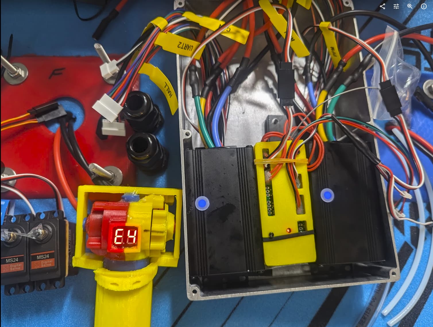
I’ve tested my setup with a basic configuration, using just the remote, and have tried different ESCs like the Flipsky 75350, 75100, and Flycolor X-Cross with a 5 Volt BEC, but the results are the same.
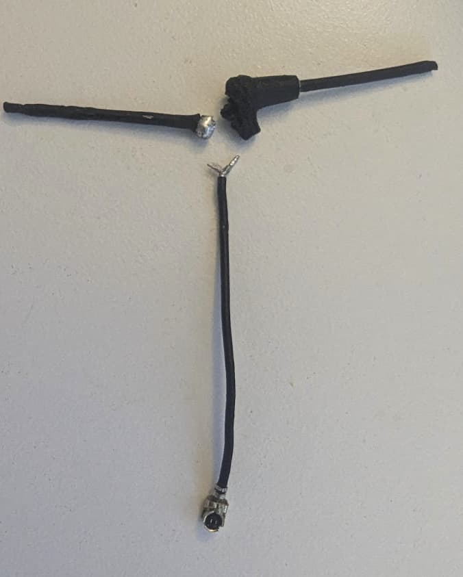
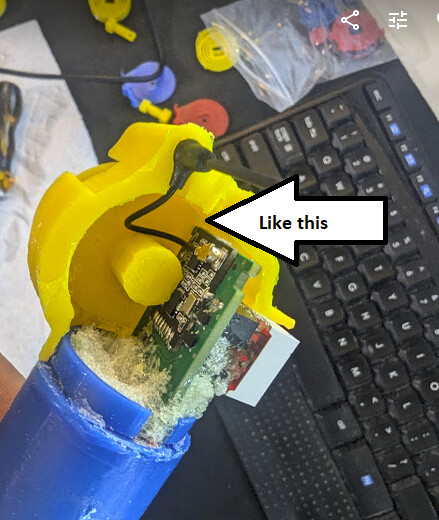
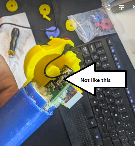
The receiver antenna is positioned outside the metal box and nearby, yet the problem persists. I’m confident my wiring is solid—everything functions correctly, even at long distances, and there are no soldering issues that could cause a short.
I’m using the default version 1.7 settings with only one modification: my receiver hardware includes the Longrange Servo addon, which Jaime added when I bought the remote to control the servo, and it works fine. Aside from that, all my configurations are at the default settings for differential speed. Even when testing with a simple (non-differential) setup, the E4 error and sporadic connection issues continue.
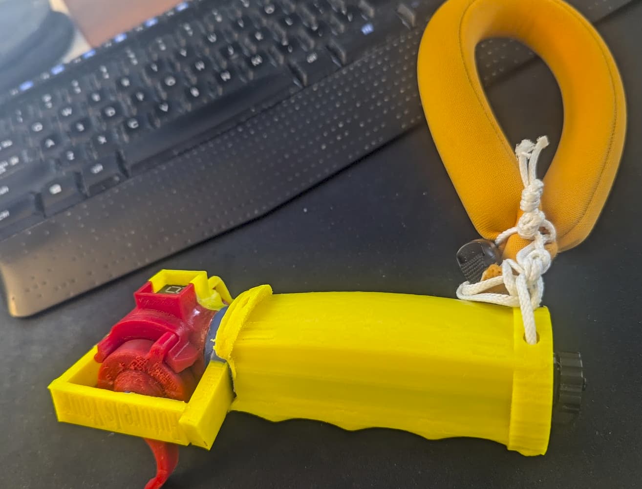
My current setup in a nutshell: You need to push the throttle to power up the remote, and there are no gears starting at 9 speed. But again, none of these seem to matter because I get the same E4 error and sporadic connection, even at the very basic default configuration. I’ve completed the calibration, and all buttons on the remote are working correctly, so the magnets and switches are all good. I tested my setup with Servos and BECs only the same thing.
Any help or guidance would be greatly appreciated. Thank you all!
I’ve listed my configuration files below in case there are any issues there but please let me know if additional details are needed:
Receiver SHARED_CONFIG.h file
//These Adresses need to consist of exactly 5 letters or numbers
uint8_t rxAddr[6] = {"SATAI"}; //From Rx To Tx (Board to Remote)
uint8_t txAddr[6] = {"SATAO"}; //From Tx To Rx (BRemote to Board)
//Output Debug Information
#define DEBUG
//#define SERVO_STEERING_ENABLED //Servo Output on Aux1 (Modification needed, email me)
#define DIFF_STEERING_ENABLED //2nd Motor Output on Aux1 (Modification needed, email me)
//#define REVERSE_ENABLED //Puts remote into reverse mode: Only two "gears": Forward (F) and Reverse (P)
/*
* Rx Specific
*/
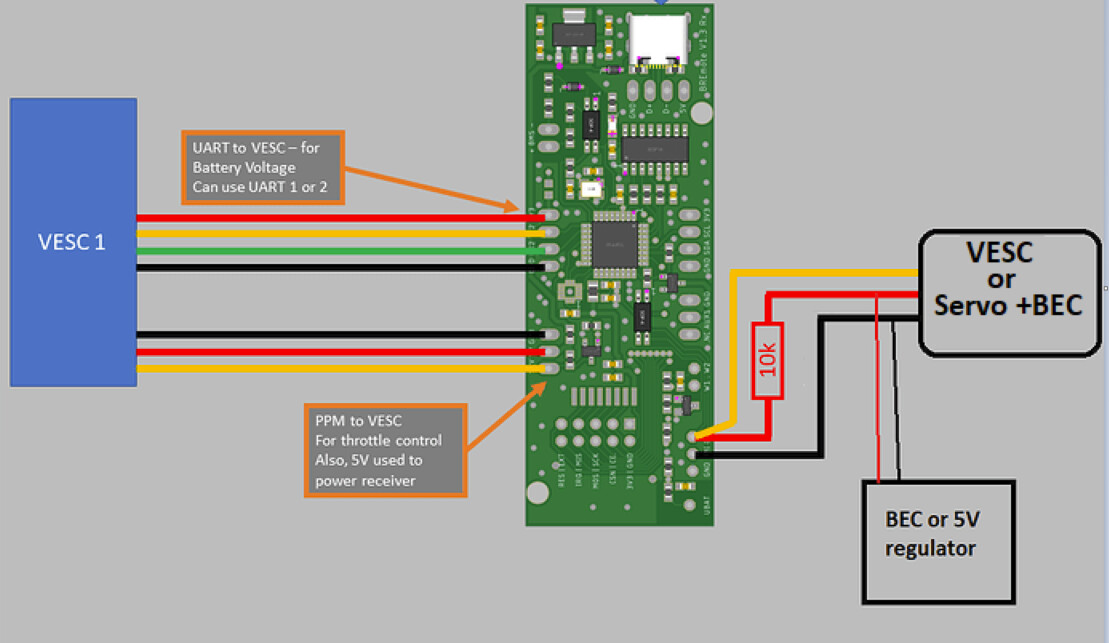
//#define USE_VESC_UART //If VESC is connected via UART
//#define USE_UBAT_MEAS //If UBAT should be measured via Analog Input (will be overwritten by VESC)
#define ANALOG_UBAT_FACTOR 0.853688 //Calibration factor for analog UBAT input, default: 0.025869
//Foil Battery Mapping
#define FOIL_BAT_EMPTY_AT 100 //10*V (e.g. 200 = 20V)
#define FOIL_BAT_FULL_AT 600 //10*V (e.g. 200 = 20V)
//Wetness Detection
#define WETNESS_DET_ACTIVE //If Wetness Detection should be active or not (generates E7)
#define WETNESS_SENS 500 //Wetness sensitivity. 0: Least sensitive, 1024: Most sensitive, good range: 100 to 500
#define WETNESS_HYST 50 //Wetness hysteresis. WETNESS_SENS - WETNESS_HYST must always be greater than 0, WETNESS_SENS + WETNESS_HYST must always be lower than 1024, good value: 50
//#define BMS_DET_ACTIVE //If External BMS Input should be read or not (generates E8)
/*
* Error Codes (don't change)
*/
#define ERR_PACKET_CONTENT 3
#define ERR_NO_ACK 4
#define ERR_EEPROM 5
#define ERR_NRF 6
#define ERR_WET 7
#define ERR_BMS 8
Receiver BREmote_Rx.h file the differential/servo section but I did not make any changes and Vesc to gets connected to EM1 (connection I believe):
#ifdef SERVO_STEERING_ENABLED
  #define EN_AUX1 A1
  #define EN_AUX2 A2
#endif
#ifdef DIFF_STEERING_ENABLED
  #define EN_AUX1 A2
  #define EN_AUX2 A1
#endif
Transmitter SHARED_CONFIG.h File
/*
 * This is the only file a user should make changes
 */
// #error "Please change the adresses below to someting unique for your setup!! Do so both in Tx and Rx SHARED_CONFIG.h! Then delete this line"
//These Adresses need to consist of exactly 5 letters or numbers
uint8_t rxAddr[6] = {"SATAI"}; //From Rx To Tx (Board to Remote)
uint8_t txAddr[6] = {"SATAO"}; //From Tx To Rx (BRemote to Board)

//Output Debug Information
  #define DEBUG

  #define STEERING_ENABLED                    //If steering feature is enable (see also fine tuning at "Tx Specific")
  //#define REVERSE_ENABLED                     //Puts remote into reverse mode: Only two "gears": Forward (F) and Reverse (P)
                                                //Important: Also update RX! Otherwise in failsafe the VESC will be sent wrong commands!
/*
 * Tx Specific
 */

    //Behaviour of the User Interface
      //#define NO_LOCK            //No locking function, as soon as remote is on, throttle is active
      //#define NO_POWERBUTTON     //The toggle button cant turn off the remote (the remote will power off automatically if the receiver is off for > NO_ACTIVITY_TIMEOUT (see below))
      #define NO_GEARS           //Gears can't be switched (set STARTGEAR to 9)
      #define THR_TO_PWRUP       //If throttle also needs to be pushed to power the remote (helps if remote turns powers up on its own)
      //#define DONT_SEND_IDLE     //If the remote should send packets in idle (no trigger applied), contiues for a short time set by TOGGLE_BLOCK_TIME
                                  //Useful, if 2 or more people have one remote each and control the same towboogie

      #define STARTGEAR 9         //The gear that is set after poweron or unlock (0 to 9)

      #define SHOW_TEMP           //If display should also show temp (alternate btw. temp and bat) or only show bat

    // Hyteresis
      #define TOG_DIFF 8                          //Hysteresis for Toggle (30 for toto)
      #define TOG_STB_DIFF 8                      //Hysteresis for Standby Toggle (30 for toto)
      #define THR_STB_DIFF 10                     //Hysteresis for Standby Throttle

    // Steering Feature (e.g. for tow boogies) - Enable at top of this file
      #define STEER_TOG_DIFF 15                   //Sensitivity of Steering
      #define STEER_DEADZONE 3                    //Deadzone for steering
      #define TOGGLE_BLOCK_TIME 500               //How long toogle button is in steering (*10ms)

    //Timings
      #define UNLOCK_TRIGGER_TIMEOUT 5000         //Time after unlock until trigger times out (ms)
      #define LOCK_PWR_WAITTIME 2000              //Time toggle needs to be pressed to power off or lock system (ms)

      #define GEAR_CHANGE_WAITTIME 100            //Time toggle needs to be pressed to change gear (ms)
      #define GEAR_DISPLAY_TIME 1000              //How long the new gear is shown (ms)

      #define ERR_DELETE_TIME 2000                //How long the "E-" is shown after deleting an error. In this time, the user can also change gear, even if the error is still persistent (and therefore will be shown again after this time is over)

      #define NO_ACTIVITY_TIMEOUT 60000           //Turn off power if no button is pressed and receiver has no connection (ms)

    //Internal Battery measurement
      #define INT_VBAT_CALIBRATION 0.004290224    //This converts ADC Bits to Voltage
      #define INT_VBAT_FULL_AT 410                //Voltage at which 100% internal Battery is displayed (100*V) DEFAULT 410
      #define INT_VBAT_EMPTY_AT 340               //Voltage at which 0% internal Battery is displayed (Also the protection limit), MIN: 34V (100*V) DEFAULT 340
      #define FOIL_VBAT_WARN_AT 10                //Percent at wich VESC Battery triggers a warning (%)

    //For Debug, Viration Motor can be disabled
      #define MOTOR_ENABLED


#ifdef REVERSE_ENABLED
  #define MAX_GEARS 2
  #define STARTGEAR 1
#else
  #define MAX_GEARS 10
#endif
/*
* Error Codes (don't change)
*/
#define ERR_PACKET_CONTENT 3
#define ERR_NO_ACK 4
#define ERR_EEPROM 5
#define ERR_NRF 6
#define ERR_WET 7
#define ERR_BMS 8
This is a 10S12P with two VESCs, and each vesc able to supply 5volt for receiver.
I have other questions, but I will ask those in separate relevant threads.