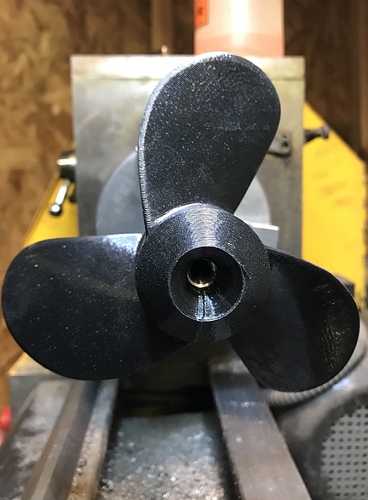
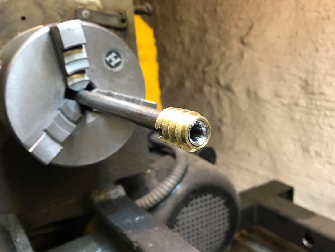
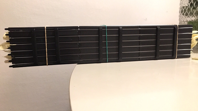
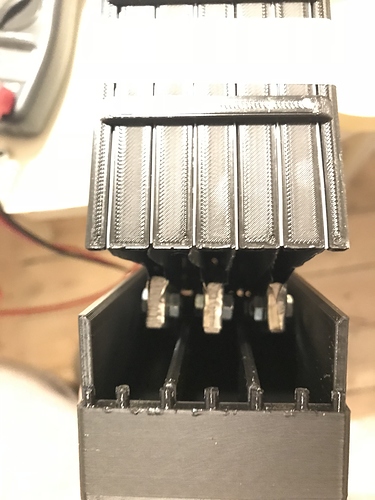
Look at the first picture. I replace the original shaft with a hollow one. Thrust bearing is placed inside of the ball bearing. Prop is held onto the shaft using a ensat thread that is machined to fit the hollow shaft. More pictures coming as I get the motor.
yes i saw the first picture, i was wondering why you chosse to put the thrust bearing at the place, pulling force on the mast will go by 3 parts (glued?) instead of just one at the back ?
I agree with @Alexandre having the force placed closer to the mast would be an advantage as the forces will not be pulling the two outer seals apart. moving the forces towards the mast helps to remove a mode of failure.
@Riwi you are doing some very clever stuff it is very nice to see the creative thinking & design work that you are doing. I look forward to seeing the development.
Best regards,
Alex (AKA theone)
Hi!
Ok I get it! That’s great feedback. The reason for placing it there is to make it serviceable. Since the alu-tube will be glued to the mast mount I won’t be able to reach the bearing if it is placed behind the motor.
It might be that the epoxy or the 3D parts won’t be powerful enough for the thrust. We will see.
I guess the mast mount can be redesigned to house both the shaft seals, the shaft collar and the thrust bearing. A great idea for version two 
Thanks
Rikard
Using a stainless thrust bearing and a stainless shaft collar would make it possible to have them on the “outside”.
The duct would be redesigned to house both seals and the ball bearing. The part in between would be eliminated. The duct would be fitted to the 3D part that is glued to the tube…
Let’s talk batteries. I know cylindrical is the way to go but I like it simple 
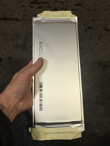
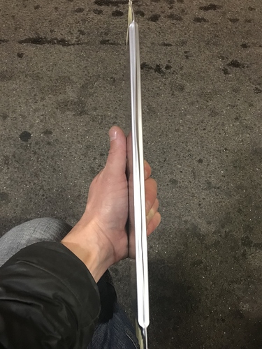
Just got my hands on 12 li-ion cells from a banged up Kia Soul. Cells are 42,5ah 4.2V and the weight is 750grams. They can handle 10C without generating to much heat.
I will arrange them in two 6s packs.
Shared. I am tempted to add that this pull setup is not present in the 6 patents I’ve read so hopefully cannot be patented now.
Haha! I love that fact 
Foil to the people!!!
I see some issue though as it will act as a perfect sea weed and plastic bag hoover.
You may design some front triangular prop cage to have obstacles diverted before reaching the prop, a bit like a locomotive front shield
If I acctually get to the stage were I am able to cut sea weed I will consider it a win 
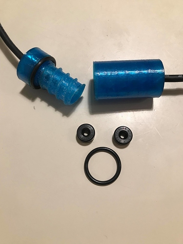
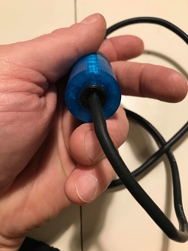
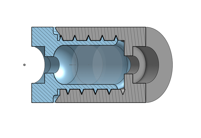
Made a prototype for water proofing my XT150 connectors that will be placed between the mast and the board. I use two lip seals 4x12x6mm and a o-ring 19.5x3mm togheter with a 3D-printed shell with threads. Its a very tight fit for my 10Awg wires. I used a bit of oil in order for the shell to “spinn” on the wires. I think 4,5mm would have been better but i didnt find any.
There is no room for the plastic covers that come with the XT150 inside the housing.
I will add the STL if the overnight test is successfull.
Looks great! Clever to use shaft seals to rotate on the wires. Perhaps a radial o-ring groove could remove the threads and give a good seal as well.
We will use that design it is a great idea, thank you for sharing.
great idea, I like that. Thank you for sharing
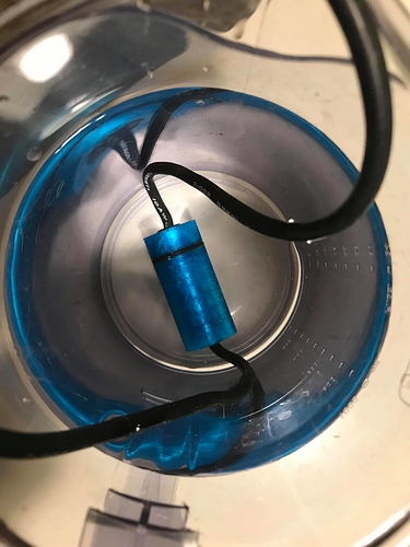
100% dry after 10 hour at 15cm depth.
Here is the STL.
https://1drv.ms/u/s!AiqyEh4Sf4KAhoB8QOKlyqunB939fA
You will most likely have to do a little sanding to get a smooth feeling in the thread. I added a layer of clear coat to the 3D part as well.
Enjoy!
Hmm, yes that would make it much easier and faster to print. Threads are demanding and requires some after prep to work in a good way. I like the lip seals. Thinking about using the on the “board side” as well. 3d print a “wall” with three pockets for lip seals. Epoxy the wall to the board and you have a water tight cable gland that requires minimum space.
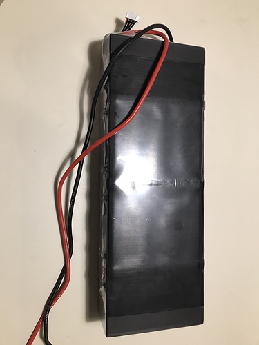
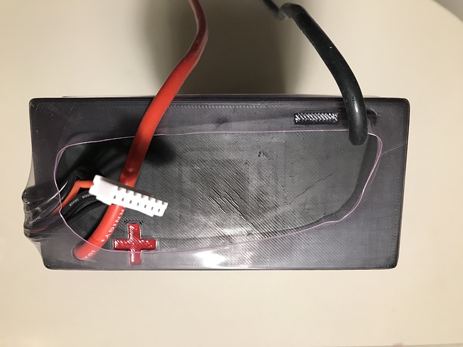
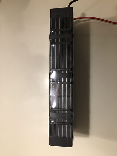
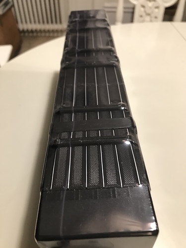
Battery update!
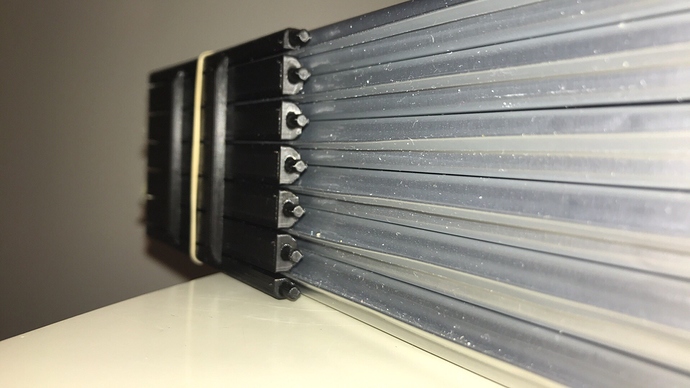
I’ve CAD:ed, printed and tested.
First 6s pack is now done. 42,5ah cells from sk innovation. They are found in the car Kia Soul.
Frame in PLA. Surface of cells protected with 1mm rubber. Everything is wrapped in a gigantic heat shrink tube.
Looks Good!..
