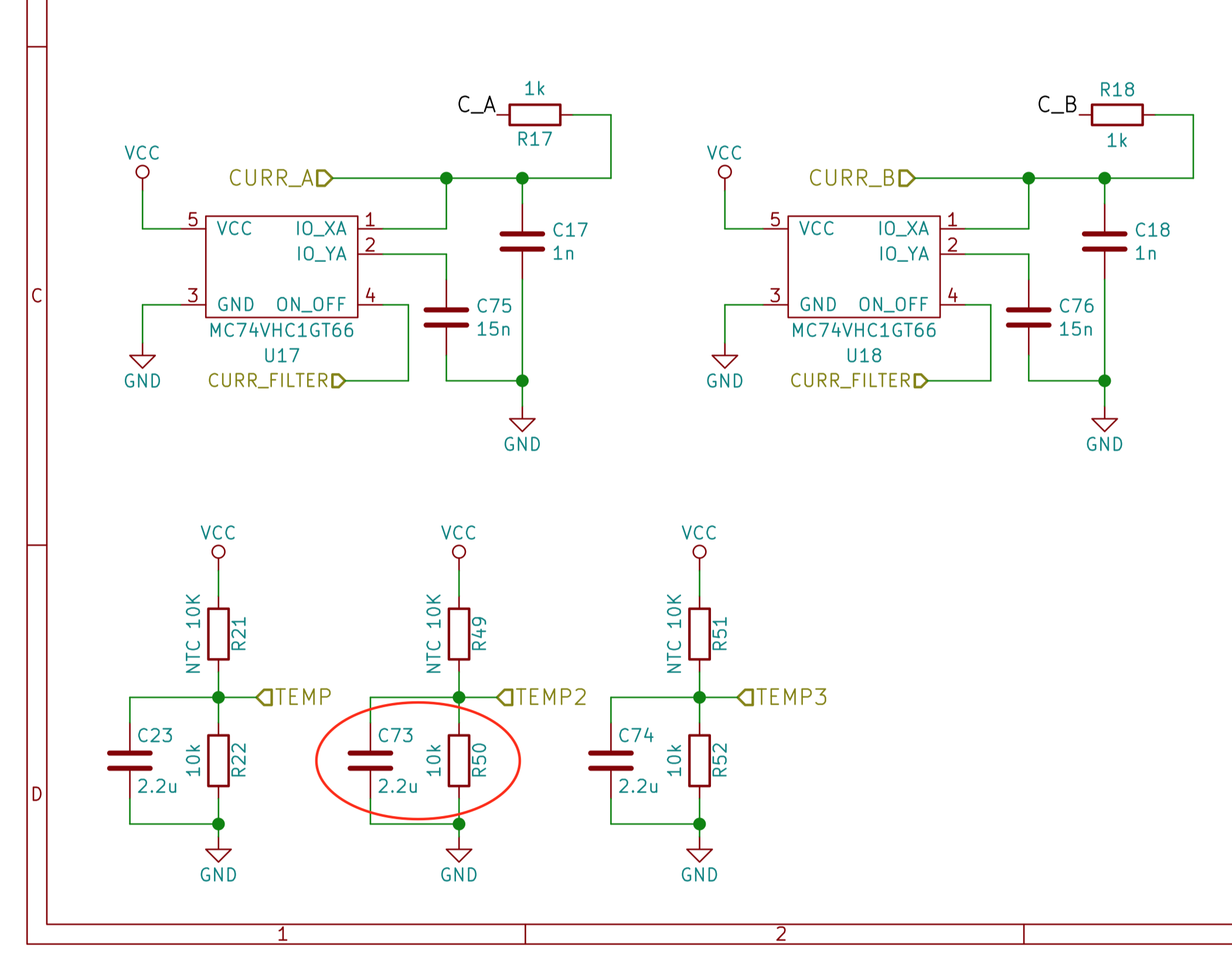
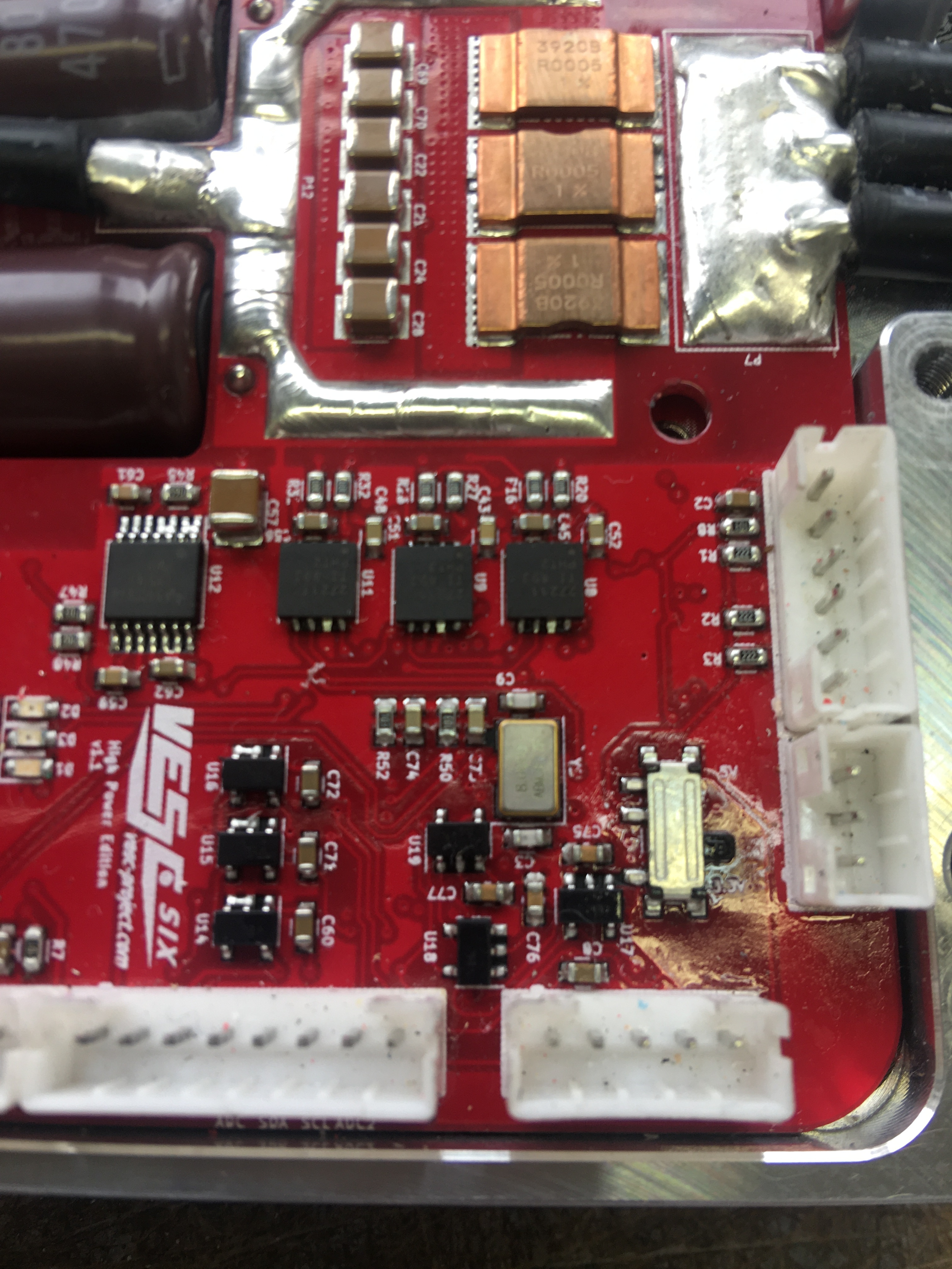
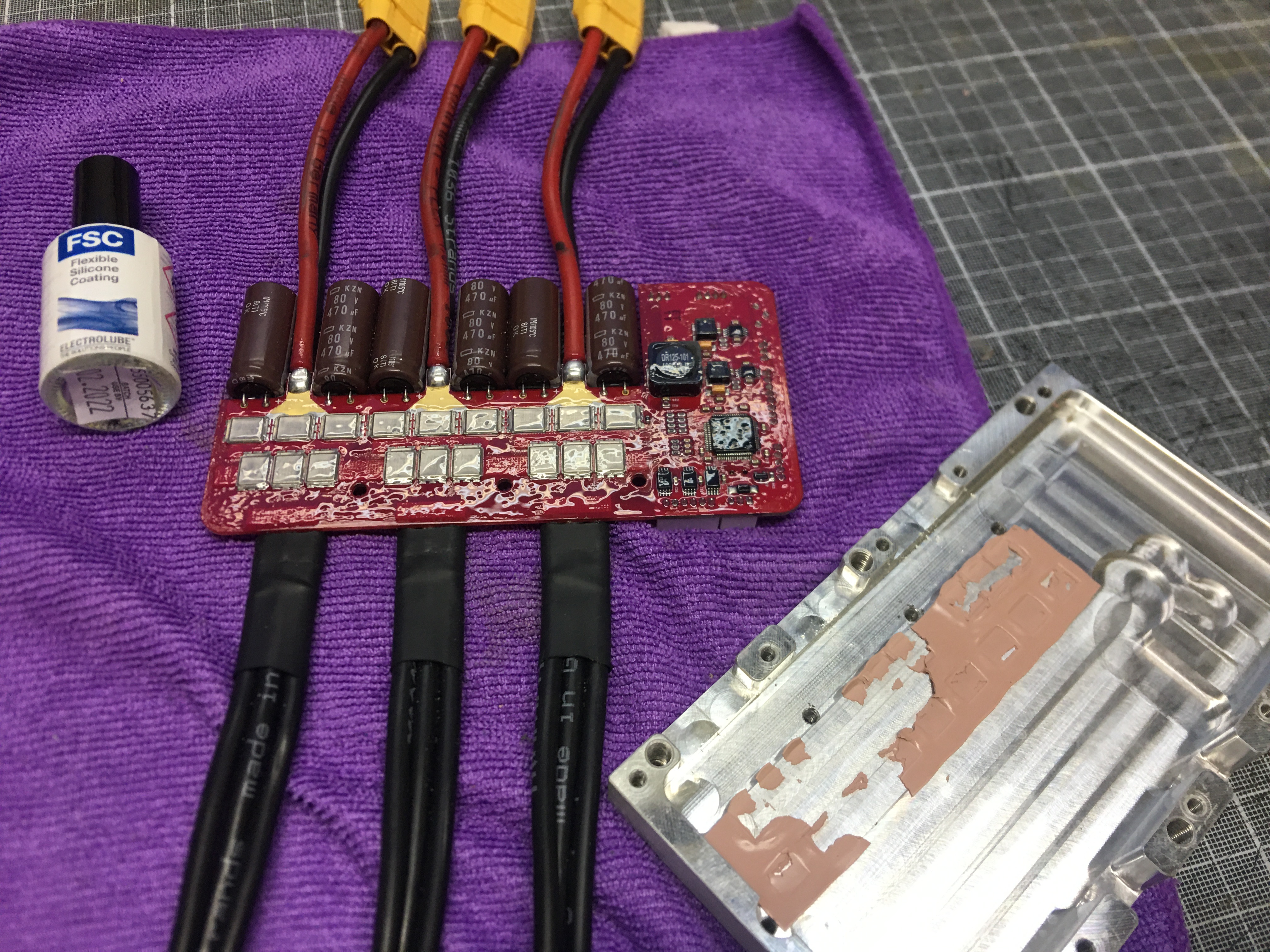
I can’t read the part designators but the schematic is available online. Share the circuit part for the blown up part. Wild guess maybe it is the analog or pwm filter parts that somehow got shorted to high voltage
Hi.
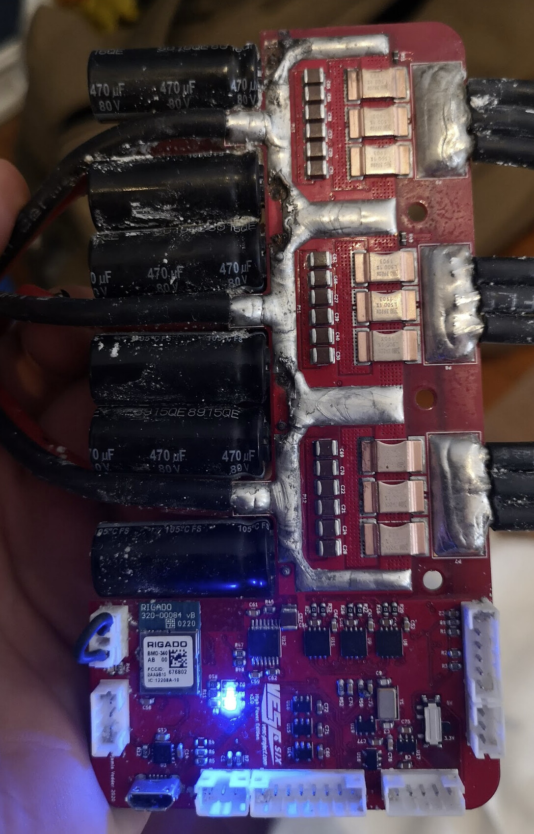
I think it’s probably dead. Sad to see. 
Next time put corrosionX in the enclosure. Fill it till the fluid it just flush with the top of the VESC. This will keep it constantly coated, provide cooling, Corrosion protection, and won’t effect the bluetooth signal.
Moisture is hard on electronics!

2 Likes
Hmm, i have no idea.
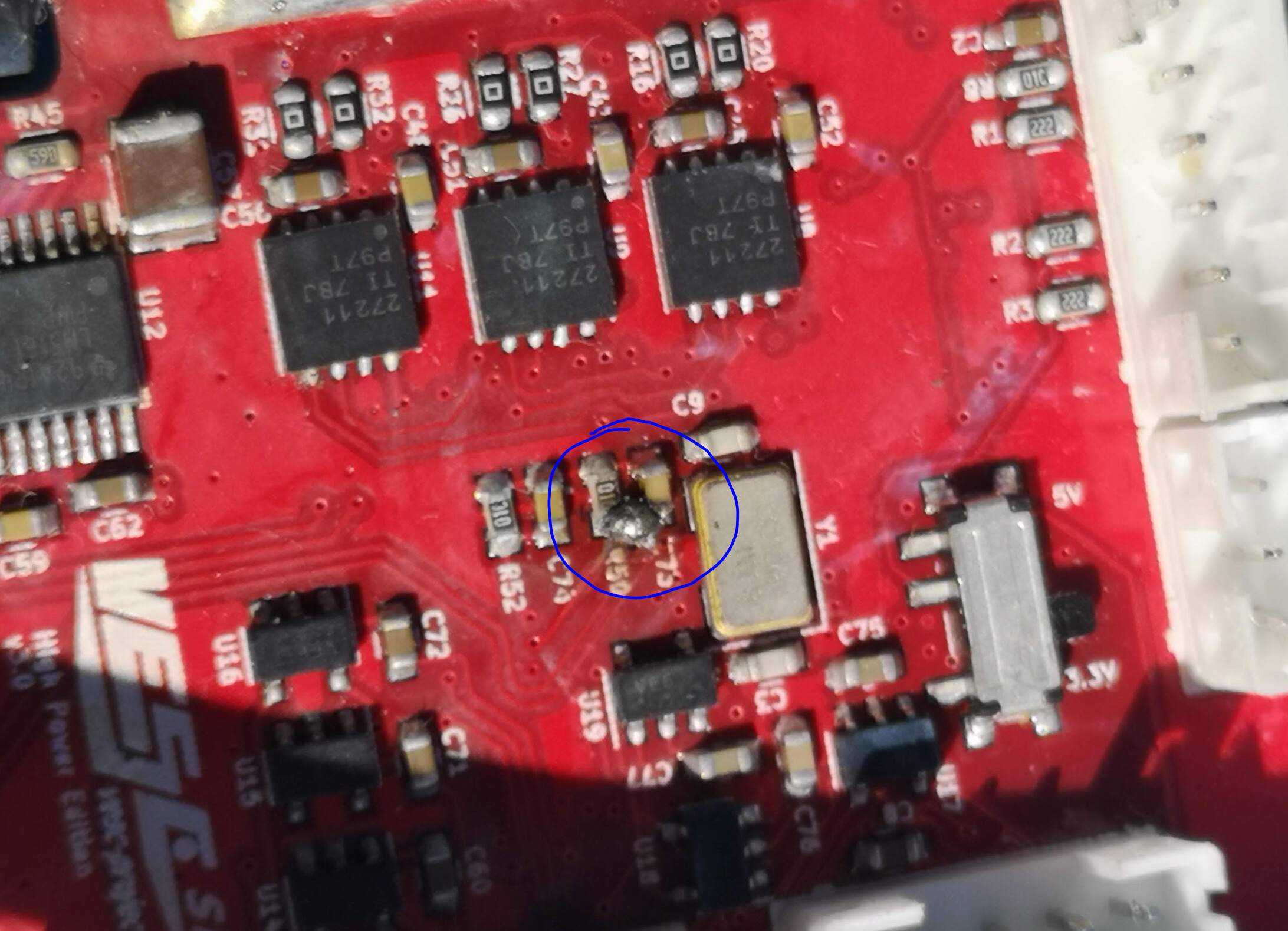
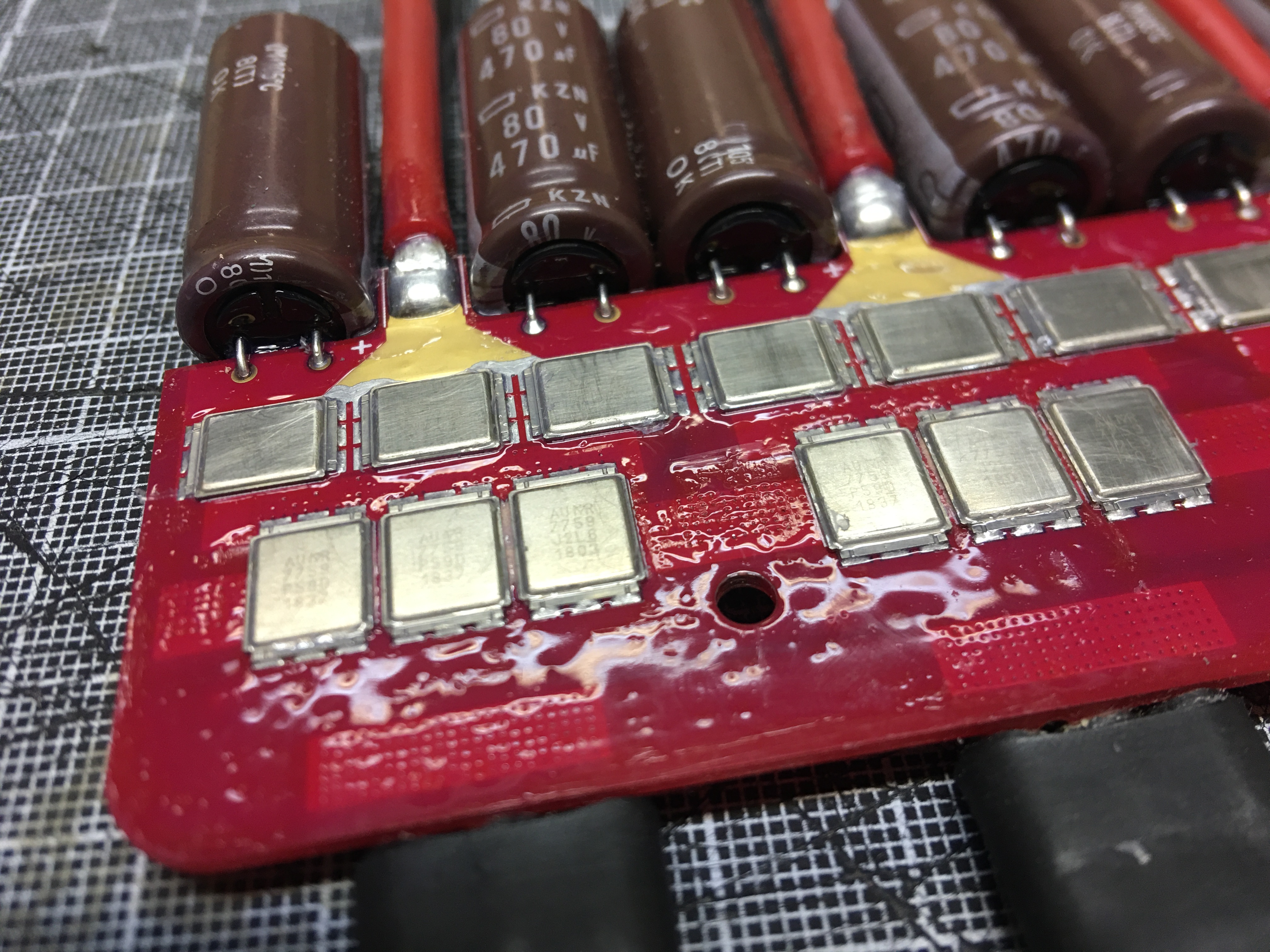
but curious if this solder joint is supposed to be there? it could be I have dropped solder ball down inside the esc?
Thanks for the suggestions!, the Zesc looks interesting; nice and compact.
I will do a thorough clean in Isopropanol and cross my fingers, hehe
I also have a local Efoil enthusiast, that is developing a custom ESC. He is kind enough to borrow me one of his prototypes! Rated for 180A and smaller format than the vesc 6. Maybe he will share or make the design available in the future for us all?
Pretty sure that solder ball shouldn’t be there.
But looking at the schematic the voltage divider resistor R50 and the filtering capacitor C73 for the temp sensor are connected in parallel anyways, so it doesn’t look like its the problem.
That Zesc does look interesting and is a nice price too.
This is the most compact option and probably the best form factor I have seen: A200S V4.1 - TeamTriforceUK
Agreed, but it’s 600€+ for us in EU now after brexit. Not an option for most…
Surely with Trampa you suffer the same fate?
They should probably subtract VAT if they are exporting, but I know a lot of businesses are not set up for that yet.
1 Like
so strange, hmm now i don’t know what to do, powered it up now and now the blue LED is on.
will try some more testing tonight!
Maybe cleaning fixed it?
1 Like
Mine is the first batch before R1 , may be they added this solder after (?)
Cleaning worked of mine rear Sam control unit ( Mercedes ml) , a lot more expensive then a vesc
So why not ? 
Haha, I will do the same if I can figure out if mine actually works.
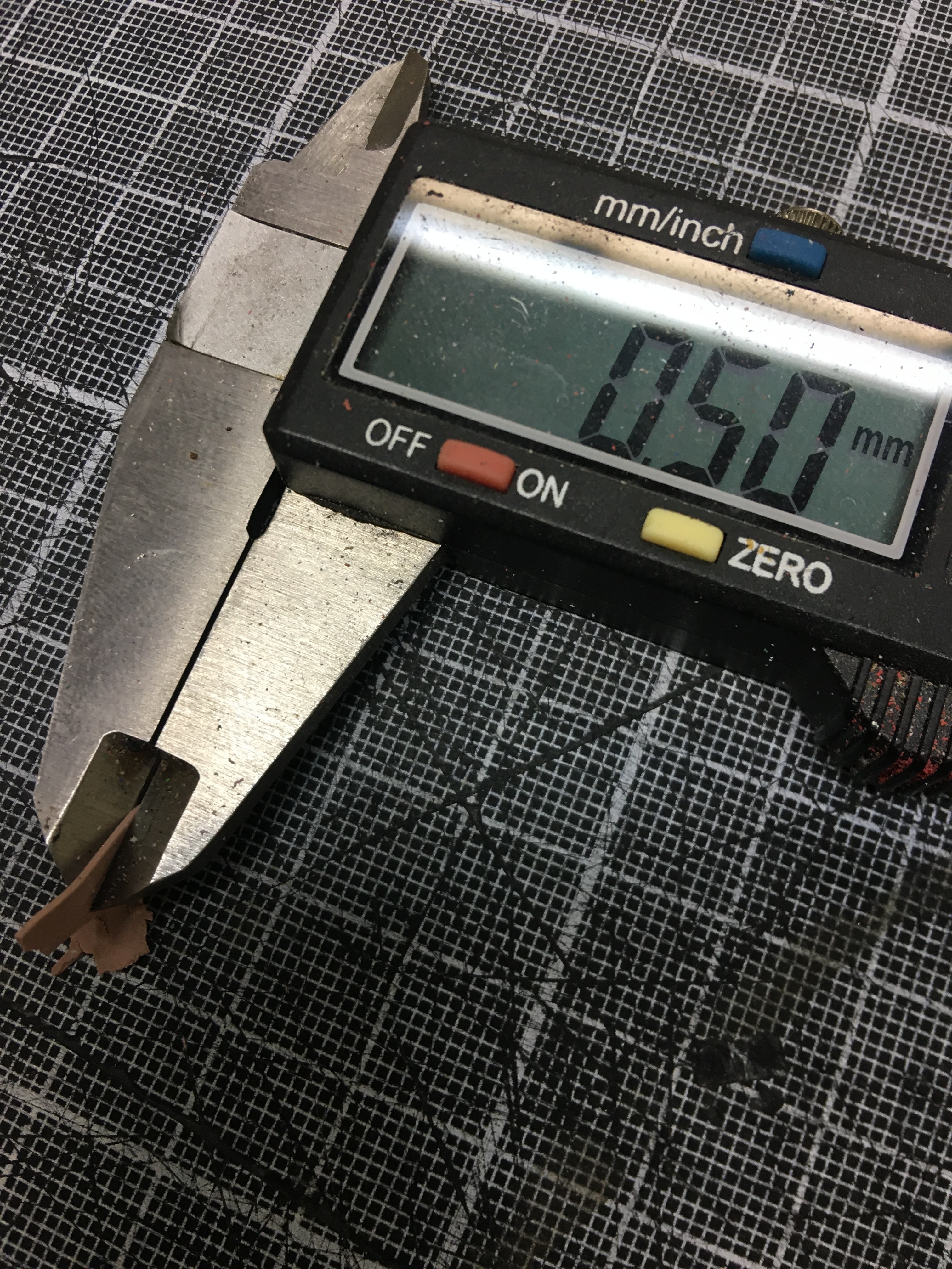
not looked for it yet, should be able to use any non-conductive thermal tape 0.2-0.4mm?
You might shed less heat if you coated the FETS as well…
Hiorth,
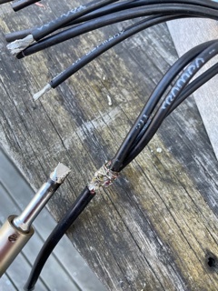
Thanks for sharing. I started to solder my 3 vesc motor wires to one 8 AWG that will go through the Gland clamp. Next conformal coat everything. After that take Corrosion X shots daily till cured.
I tied with a 40 Watt soldering iron, it was too light. Switched to 80 Watt and a fat tip. Pre-heating the bullet connectors also helped. I am thinking of sealing the Vesc box with Gorilla Tape, a very strong and waterproof type of duct tape here in the US. Water seems to be the main issue and the VESC’s are not cheap.
Coating the top of the FETs will give much worse thermal performance, would not recommend anyone else doing that, but let us know how it performs after you assemble it back together.
I think the thermal pads are from Conrad, maybe this one: Buy %product-title% | Conrad Electronic
You can also try to find one on digikey: https://www.digikey.com/en/products/filter/thermal-pads-sheets/218 Make sure it is non-conductive (not carbon) and the same thickness and softness.
I think we have used this one as replacement on the A200S v2 (same fets as 75/300): TG-AH486-150-150-0.3-0 t-Global Technology | Fans, Thermal Management | DigiKey
thank you for the link and yes i will take off the coating from the fets (i knew i ll had this comment as i posted the pic) , it is easier to take off with a bit of tickness and it looks worse on the pics
for the pad , yes i will avoid carbon and graphite, not sure what to look at for none conductive : “Dielectric Breakdown Voltage”?
tickness: something for 0.25-.5mm, oem looks hard and probably" dry out", may be i would try 0.5mm around 20-25 shore
I don’t think coating is the right thing. All those tiny vids around gets are there for better heat dissipation and yes even very thin layer of coating will reduce it. Plus solder mask coat doing the same thing and It is not possible to make sure all exposed pins are coated 100%. What I did to mitigate potential leakage was to fill the box with silicone mix so it fills all gaps around the boards and the box plus it has some thermal conductivity to help dissipating the heat. Maybe there is on out there with higher thermal conductivity: