Hey!  I’d have more incentive to use it if I actually knew how to get it built.

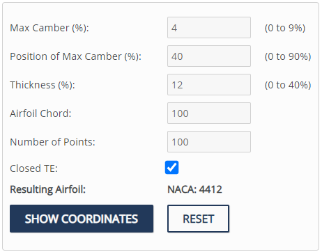
Did a bit of experimenting and found that this only happens when you add a NACA profile set. So this makes it unusable for me if it does not plot the profile correctly.
Nice explanation of .dat file format: Airfoil file *.dat - Data File - Airfoils data base
With these sections, when you open the file (change extension to txt), you should have two columns - left column = X coordinate, right column = Y coordinate. The airfoil section is represented with leading edge to the left (trailing edge to the right not like pict below)
The X (left) values ranges from 1 (right of section or trailing edge) to 0 (left of section or leading edge) and back to 1 (right or trailing edge).
At the junction point of both surfaces, mid data file, when X is close to zero, the ordinate (Ys or right column) should be zero. You need to “filter” your file manually. Excel or Open Office can help. You could also insert a (0,0) coordinate which often doesn’t exist between the last positive Y value and the first negative Y value.
Tools that help to smooth a leading edge: XFOIL has a special built in function and a NACA 4-5-6 digits generator.
Bezier tool in a CAD SW.

Thanks, ill see if i can figure out the coordinates in the dat file. At least now i know where to start digging.
NACA 4412
1.000000 0.001300
0.950000 0.014700
0.900000 0.027100
0.800000 0.048900
0.700000 0.066900
0.600000 0.081400
0.500000 0.091900
0.400000 0.098000
0.300000 0.097600
0.250000 0.094100
0.200000 0.088000
0.150000 0.078900
0.100000 0.065900
0.075000 0.057600
0.050000 0.047300
0.025000 0.033900
0.012500 0.024400
0.000000 0.000000
0.012500 -0.014300
0.025000 -0.019500
0.050000 -0.024900
0.075000 -0.027400
0.100000 -0.028600
0.150000 -0.028800
0.200000 -0.027400
0.250000 -0.025000
0.300000 -0.022600
0.400000 -0.018000
0.500000 -0.014000
0.600000 -0.010000
0.700000 -0.006500
0.800000 -0.003900
0.900000 -0.002200
0.950000 -0.001600
1.000000 -0.001300
Coordinates look right to me, its probably something to do with they way the script on winghopper interprolates them. Unless you see anything here that catches your attention?
That looks pretty funky - I’ve seen that happen before with some foil files. Ultimately, some foil .DATs are just not right. I’ll look into the back end and triple check nothing is off there. Thanks for the heads up guys - i’ll find a better way to foolproof the section import. Keep the feedback coming!
The number of points might be too low for a well defined leading edge.
Try this set of points containing 70 values : https://tracfoil.com/airfoils/uploads/files/profils/n/naca4412.dat
generated by NACALTE here: Airfoils : N - NACA, Nicolas Mathis+Marco Virgilio Ricci - Airfoils data base
Or generate online a set of 100 values for the NACA 4412:
@SoEFoil you’re a legend buddy, thank you. That did the trick.
PS: What is your opinion on the 4412 as a profile for the front wing?
1 Like
I haven’t tested with a lot of profiles, but as @SoEFoil suggested you need more plotting points in the dat/txt file, so it’s not a big problem.
One thing I did notice as well is that sometimes after you export the CAD file it reverts back to the default wing and you lose all the config data, is there a way to add the wing config to the download so you at least know where you were in the design?
I’m not a specialist. I think it might have too much camber. I’ve just (re) discovered the NACA 1306 (fast) / 1308 (all-round) 1310 (tolerant) 1312 (very tolerant) [NACA 1408 has nice polars too]
Looking for inspiration ? There is this great thread on Kiteforum praising the s-2055 not very cambered either.
I’m working on a save feature so you can have multiple wings in your account. Will keep you posted - I know how critical this is and it is absolutely a priority now. It may be a paid feature.
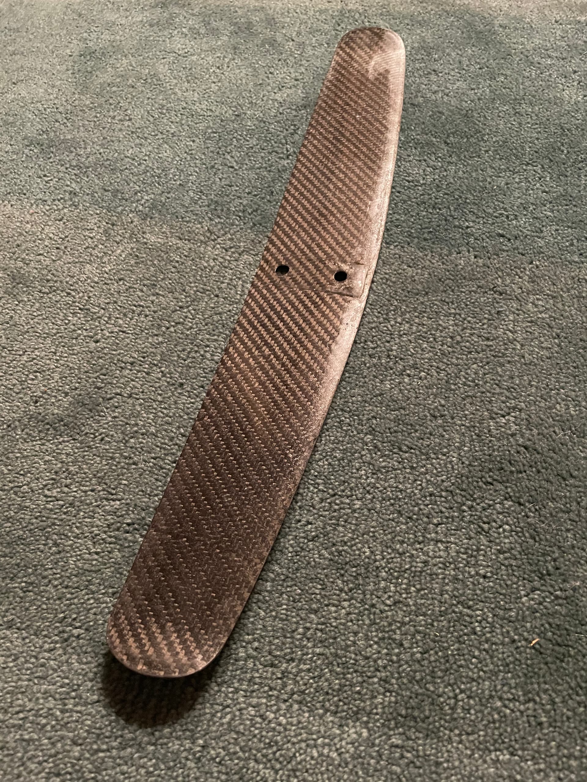
Made a rear wing from moulds based on a design made with winghopper. Thanks for sharing this great tool.
If anynone wants to build one: Hydrofoil rear wing mould by dfi - Thingiverse

5 Likes
For which foil fuselage is it ? Could you compare the old stab with this new one with a S-2055 airfoil section ?
It is for the RL Fuselage but I added two drill jigs, one for the RL hole pattern and a step file without holes so you can adapt it to any fuselage with a flat spot and threads on the bottom side of the fuselage.
I tested it with the RL 1150cm wing, it works well, especially at faster speeds above 30km/h. As the surface is only 320 cm2 (RL has 400cm2), it is a bit looser than the RL.
How do you prepare the mould? Do you sand it? Do you use any filler? Release Wax or PVA before the gelcoat?
After gluing the two parts of each half with 2k epoxy glue, I sanded the moulds with grit 200. If necessary you can use epoxy filler. Then I added gelcoat. You could sand again after applying gelcoat but then you need to sand up in steps to 2000 -3000 grit to get a nice surface. Used moldwizz as a release agent. Apply gelcoat to the mould parts, wait until it gets sticky, then add a layer of 80g glass. Then add cfk. I used 200g for the visible layer and 2x 300g biax on each half. Add tear-off fabric and put it in a vacuum bag. Cut and sand the two parts so they fit into the mould. Fill the wing with cut cfk fibres and thickened epoxy. Use clapms and/or screws to put the two mould parts together and add pressure.
3 Likes
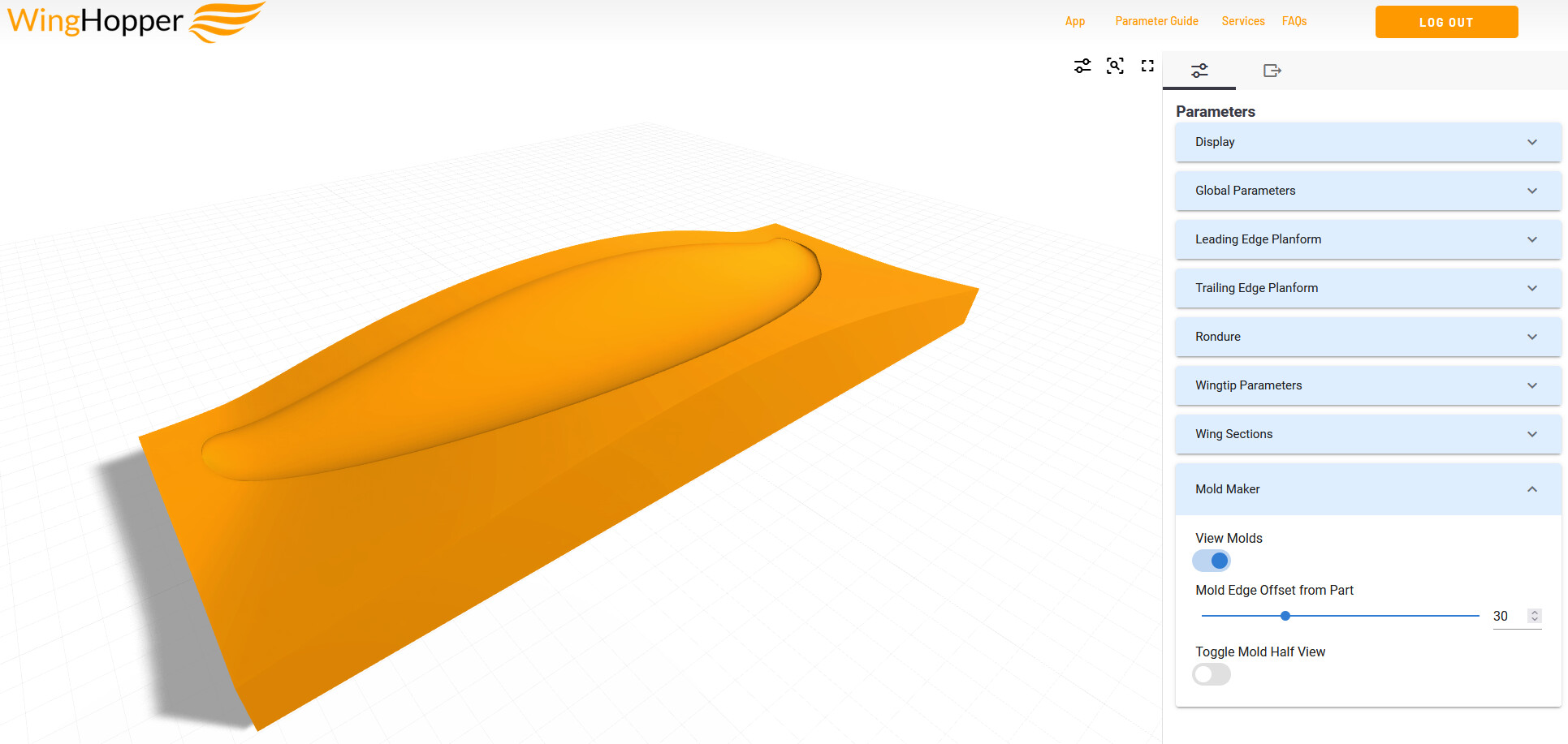
I’ve just updated the App to include a more streamlined UI with grouped parameters and… the MOLD MAKER!
The mold tool automatically generates a two-sided mold split perfectly along the leading and trailing edges.
Let me know what you think!
6 Likes
I’ve just updated the site to make the web app more robust - it was failing to calculate some parameter combinations and it’s fixed now. Check it out!
3 Likes
Hi Zach
I have just loaded your app and appreciate what you have offered. With my app I don’t have the Mold Maker Tab at the bottom of the Parameters drop down list as you show in the screen capture above. I do have View Molds and Toggle Mold Half View in the Display drop down list however selecting and applying this option doesn’t make them visible. I have tried other combinations of selections in the Display drop down list but no sign of any moulds. Is this feature an Add On? Or have to be enabled somewhere else in the App? Regards Ray