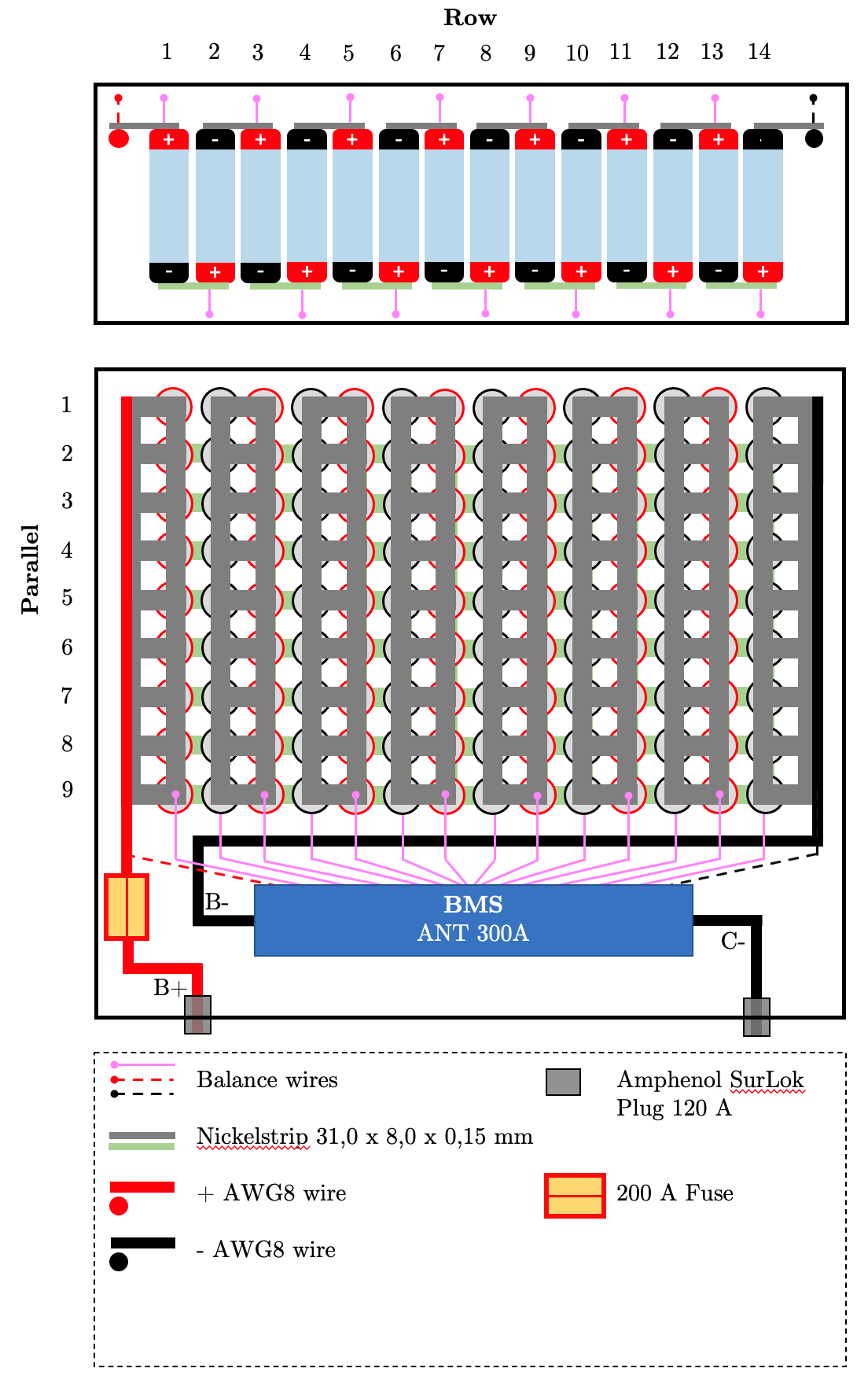
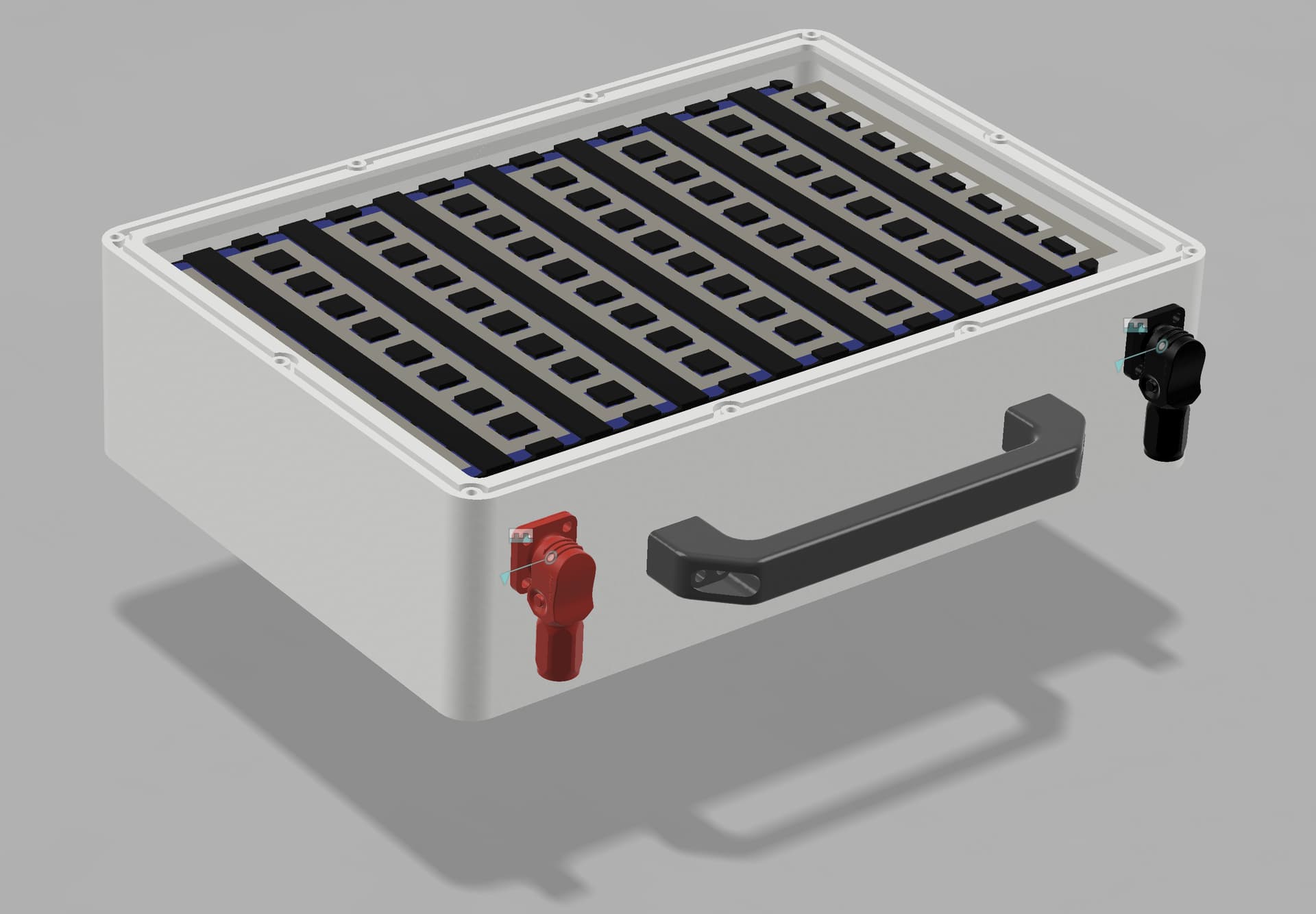
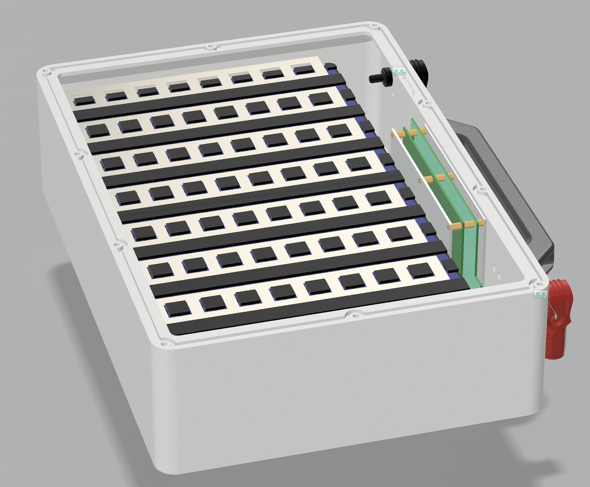
I am working on my 14S9P Samsung 40T battery build and before starting to print the enclosure, I want to make sure that I’ve considered all important aspects to fit everything in that box.
Concerning the fusing, I’ve decided not to go with individual cell fuse wires/nickelstrips. Instead I want to use one or two typical car/midi fuses rated with 200A even though I am using a 300 A ANT BMS for charge and discharge limiting.
The question I have is where to place the fuses to ensure safe operation.
As I understand, the FETs in the BMS fail open in worst case and thus the current e.g. from the charger rushes into the cells. That’s why I would consider a fuse between the BMS and the battery negative busbar (not depicted yet in the drawing)
However, I’ve read somewhere else that fusing B+ would be enough since current flow will be interrupted anyways.
Others say, fusing is not beneficial because they cause trouble… I agree, if the chosen rating is inadequate. I personally see fuses as a last resort and if a molten 200 A fuse could prevent a total thermal runaway I would be happy enough.
Do you guys have other thoughts on that?
Any battery expert could also have a look on the wiring?
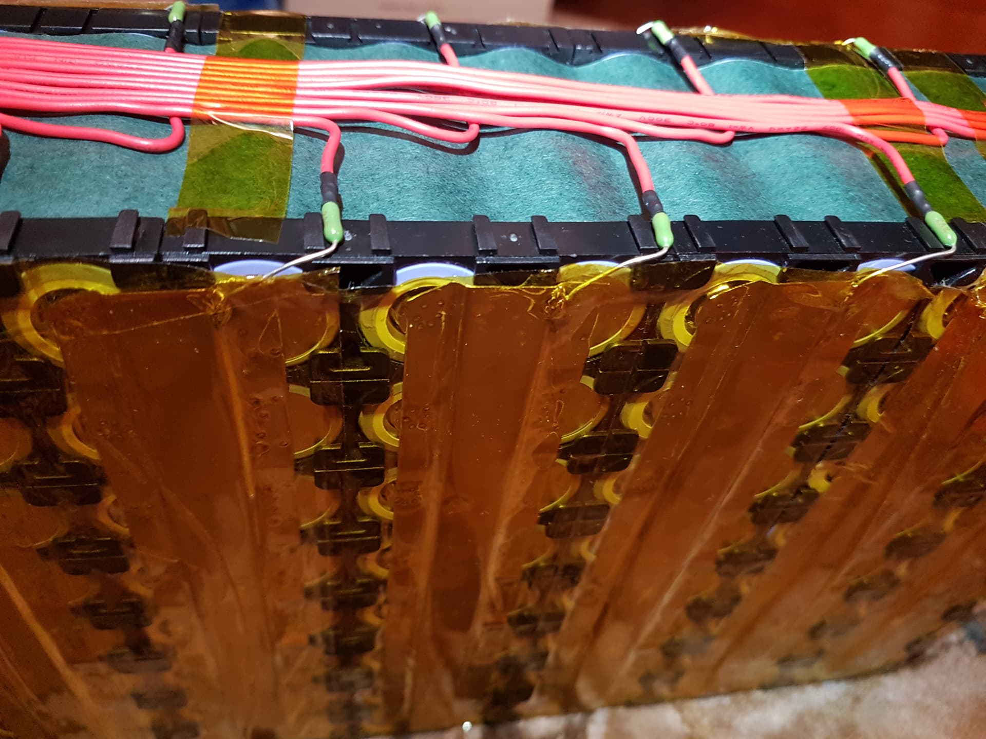
The fuse position will be fine, I think its a good safety feature, provided the nuts are secured tightly. I like to use pico 2A fuses where the balance leads join the nickel strips, in case the balance leads wear through and short each other.
I prefer wider/thicker nickel in the series direction, to reduce wasted power/heat/voltage. I use 30mm x 0.2mm nickel strip laid in the parallel direction, which gives effectively about 21mm width for each cell in series direction. 0.15mm thick x 30mm would be fine, and easier to spot weld if you don’t have a kweld.
Having said that, I just ran some calculations and 8mm pure nickel strips would be fine for most of our efoil purposes, only wasting around 5W as heat if you are pulling 45A cruising current from a 9P pack. Nickel coated carbon steel has double the resistance, and therefore double the power loss as heat, so make sure you have pure nickel. Stainless steel is about 10x the resistance of pure nickel.
Power loss = I ^2 * R
(Voltage doesn’t change loss)
Using test results from here:
Nickel 8mm x 0.15mm strip
With a 350mm length of nickel per series strip of cells (close enough to the length of 13s with 21700)
With 5A per strip - Power loss: 0.60 W Voltage drop: 0,12V Strip resistance: 24 mOhm
Eg 45A with 9p pack, 9 strips gives 5.4w waste heat
With 10A per strip - loss = 2.4w per strip
90A with 9p pack gives a loss of 21.6w waste heat
15A per strip - loss of 5.4w per strip (with 0.36V drop)
135A in a 9p pack produces a loss of 48.6w waste heat
I just picked up some Littlefuse 2A Pico fast blow fuses (resistor style) too for balance connection to my packs. Kwelding the lead of those fuses directly onto nickel seems implausible as the leads are thin and fail with vibration. Can you share photos of how you mount the resistors?
I solder the fuses onto the nickel strip as shown…
With regards to balancing current, if the BMS needs to balance at 2.75A then your battery pack is in serious trouble with unbalanced rows. Most BMS will only use something like 50-200mA for balancing, not 3amps.
pardon my mistake, no BMS just a batt charger. I shows in the instructions Hitec 2.75 amps available to balance. my I charger says 3 amp. I have to set the balance amps, last time I chose 2 amps. just sayin?
Thanks for posting your fuse mount photo, Jatem. Your .3 nickel strips are unique, where did you source them from and did you stamp them into that shape?
For my battery build, I was thinking of mounting a PCB along the pack edge, fuses secured through-hole in the PCB, and route the balance over copper traces on the board, kweld nickel cut strip from PCB to nickel strips on pack.
Regarding fuse current ratings, I was also concerned that 2A may not be enough. My BMS (similar to yours Jatem) is really slow to balance, my concern is that it is too slow–at least not knowing how far any pack can get out of balance, it could take days to balance. so…
I purchased this active balance board, and plan to tap and expose my balance leads outside the pack so I can optionally quick balance. In this config, the balance board would be outside the pack and used along with my charger, bluetooth BMS for charging and exposing cell voltage and battery temperature to VESC and Metr Pro.
However, this balancer is rated at 5Amps though…so I am also not sure if 2Amp fuses are too low rating.
Hi again , just trying to help. I`ve not built a lot of batteries, i noticed routing the balance leads if I started with the neg in the middle and saved the crossing of the leads until they came away from the battery
I use 30mm 0.2mm pure nickel strip, which I have bought from aliexp. I designed a simple printed air bending tool which I use to shape the strip.
A pcb for balance wires sounds like an interesting solution. I cover the balance wires with 50mm wide kapton so they don’t move, and then the pack is mounted inside a polycarbonate box with solid spacers, so that the balance wires aren’t squashed or rubbed against the side. I could probably get away without individual fuses, but it seems a good safety feature.
With regards to routing the balance wires, I cross the wires when they are in a hollow between the cells, so they are all parallel and not crossing when they go over the high point of each cell. Starting with the negative end seems like it would also work, but do you find it is bulky when the all 14 wires are all crossing at the plug end of the balance wires?
If the cells are in good shape, the balancing current should be very minimal, and much less than 2A.
Thanks @Jatem for the feedback, Ive only done 10 cell and it was ok. Again I think it wont work with the BMS as good as just going to the plug on the box
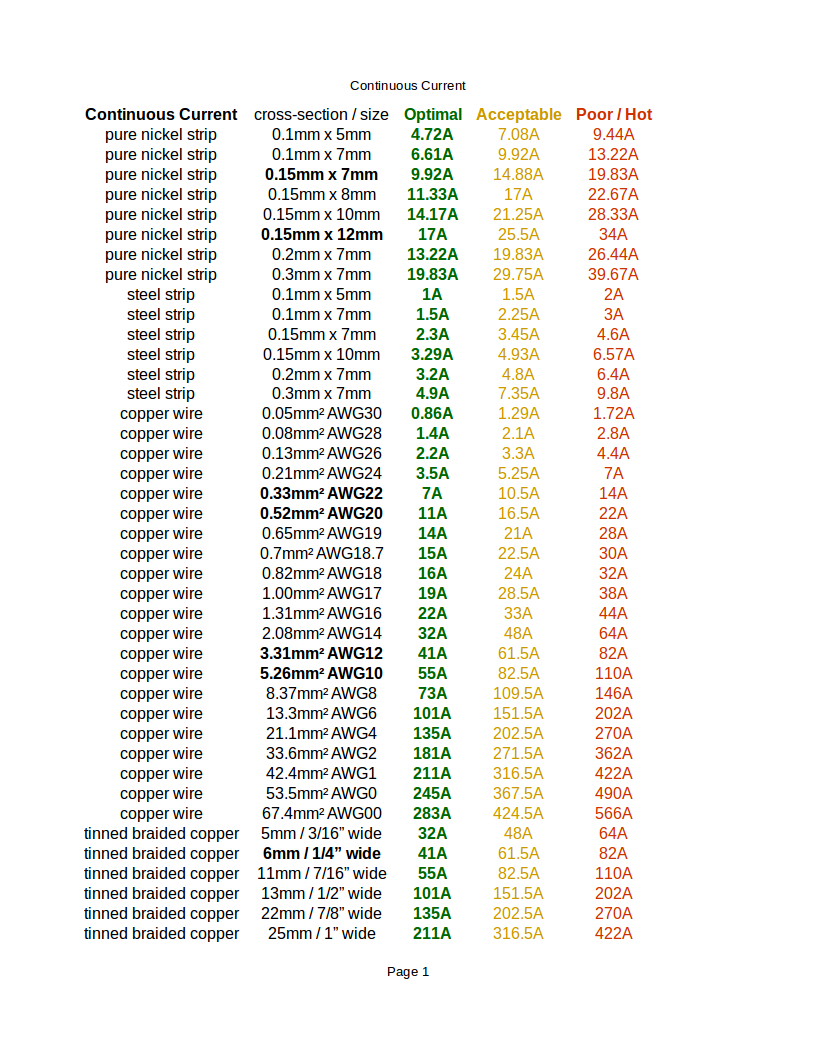
Thanks @Jatem for your inputs. I chose Nkon as a trustworthy supplier for the nickel strips, cells etc. So the strips are pure nickel. According to the commonly referenced continuous current ratings
the 0.15x8x31 mm strip should be fine.
@Quentin I will do it the same way fusing the positive wire only. What are the dimensions of you enclosure?
Maybe too late but for what its worth…I built a 14s 12p with a similar setup - I suggest you check carefully the dimensions of the BMS - mine was to wide to put vertically as in your diagram. I ended up having to lay it flat on top of the cells. Not ideal but with some fish paper and insulation its ok. The result was I had to build my battery box 15 mm taller than I would have liked and thus my board needed to increase in thickness too. Next time I will redo with a smaller BMS to be able to have a slimmer board.