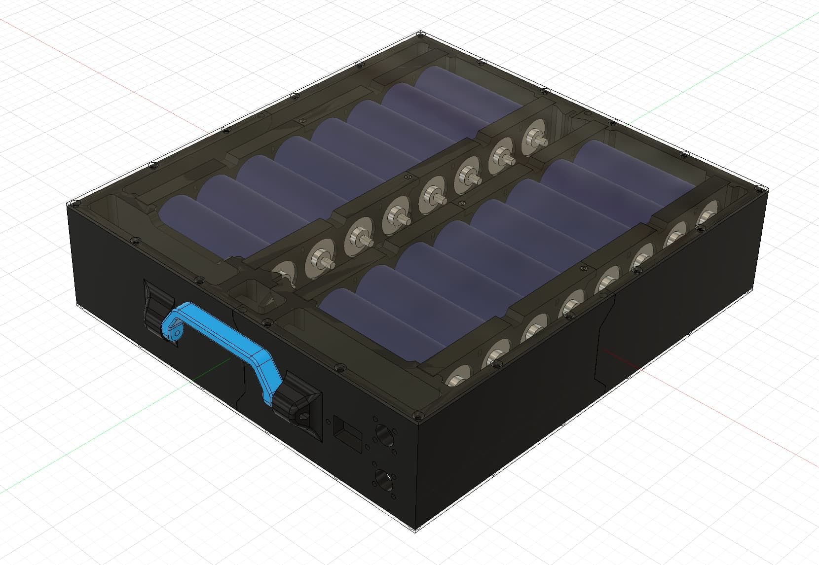
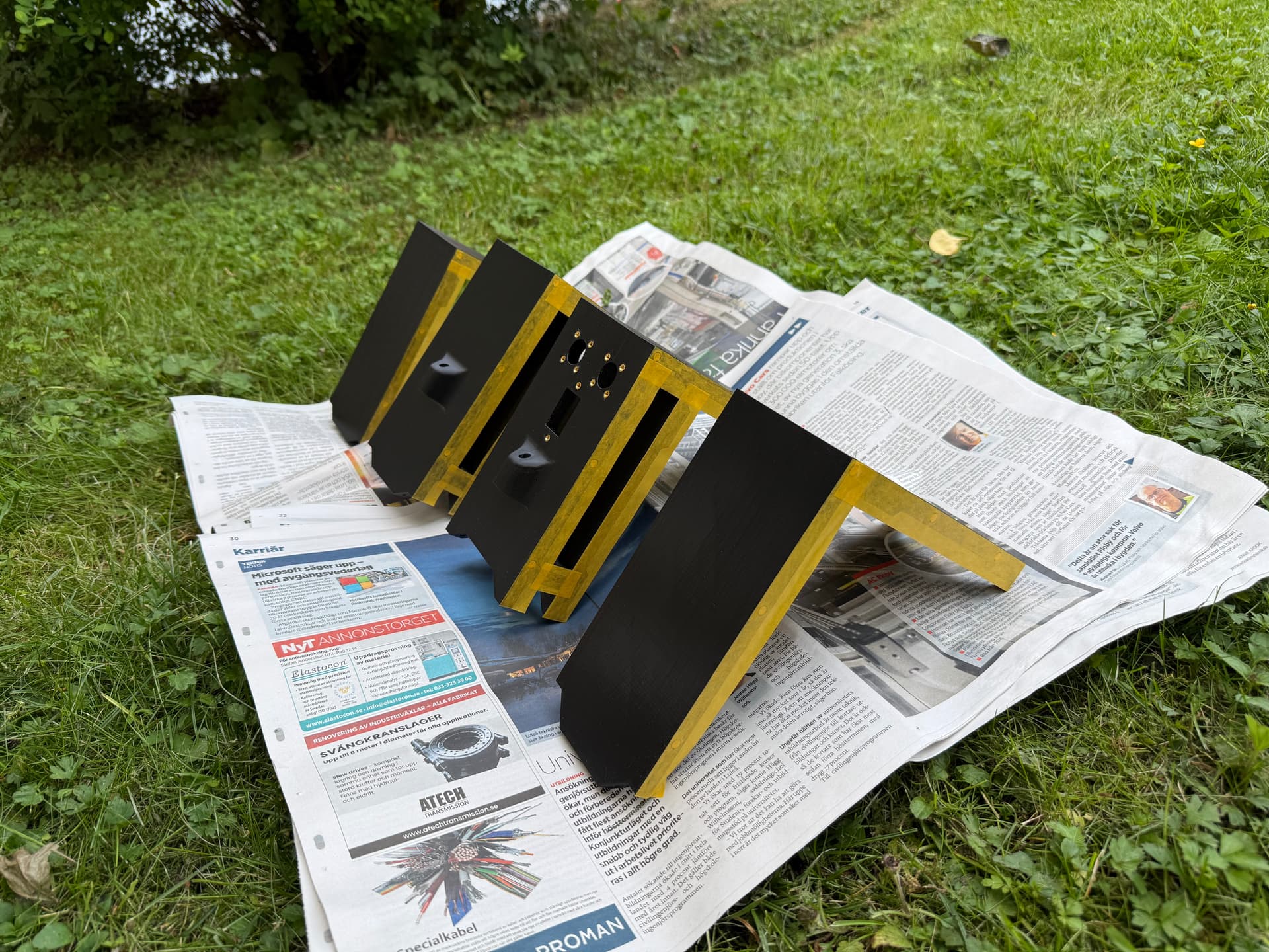
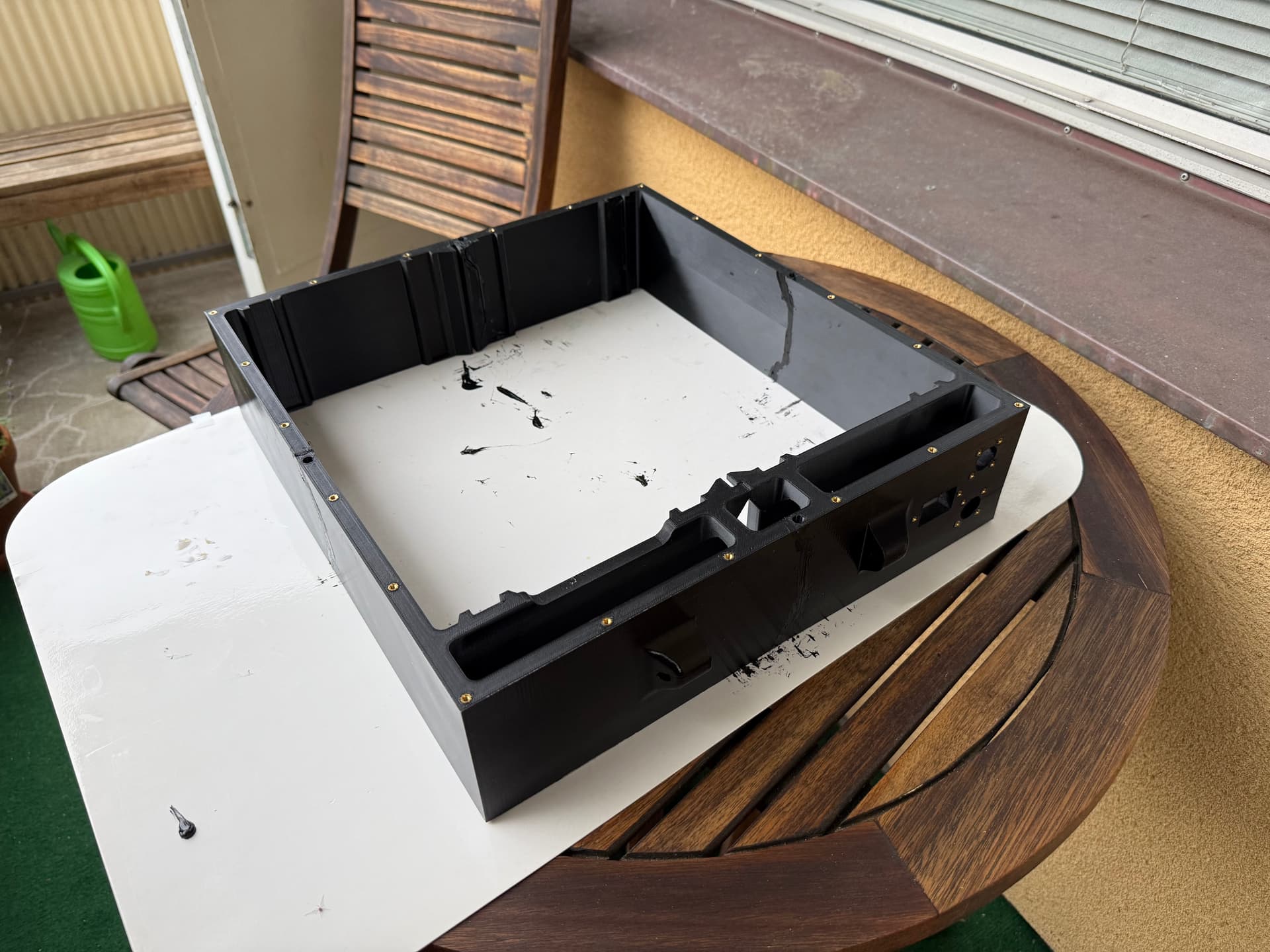
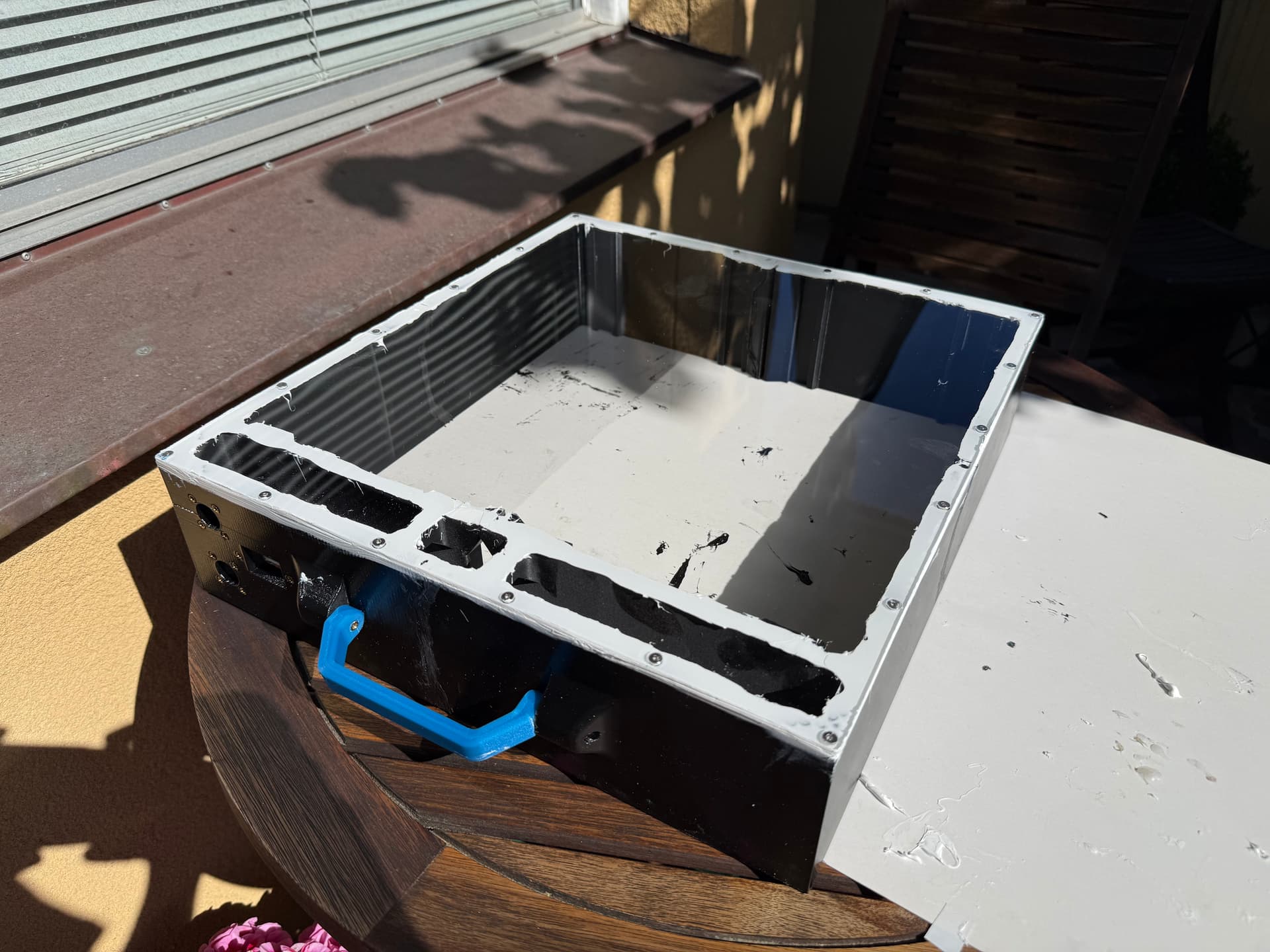
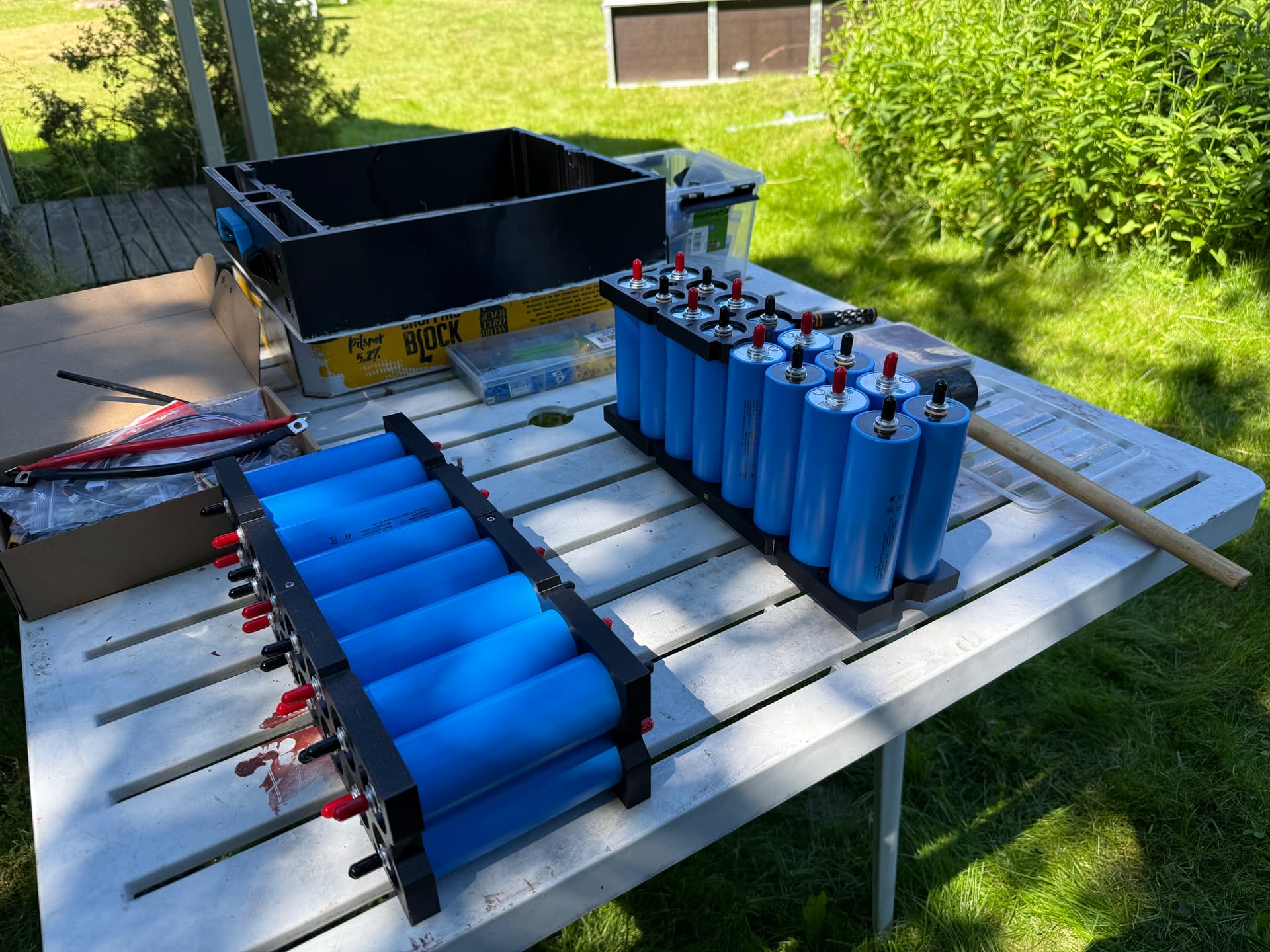
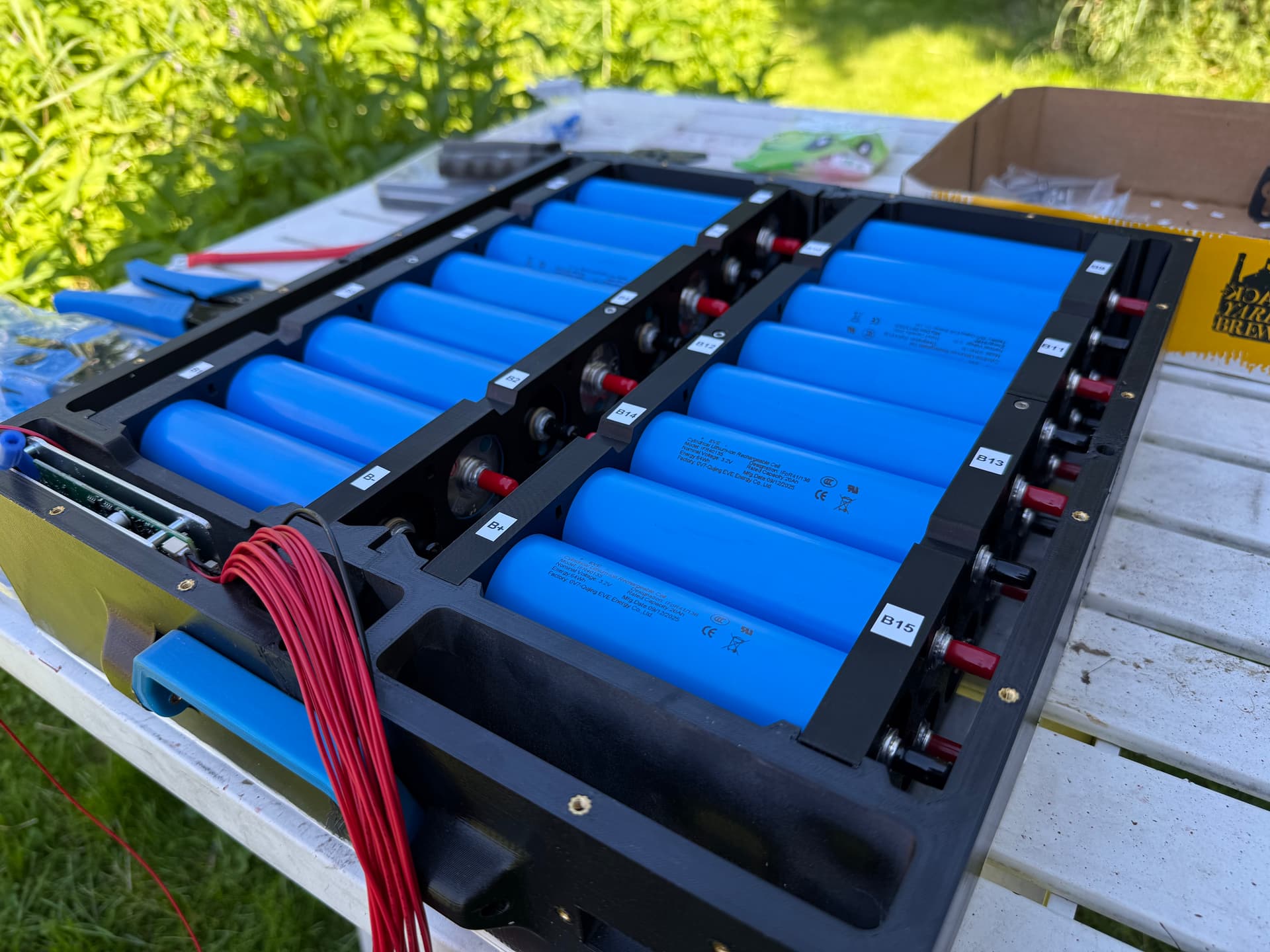
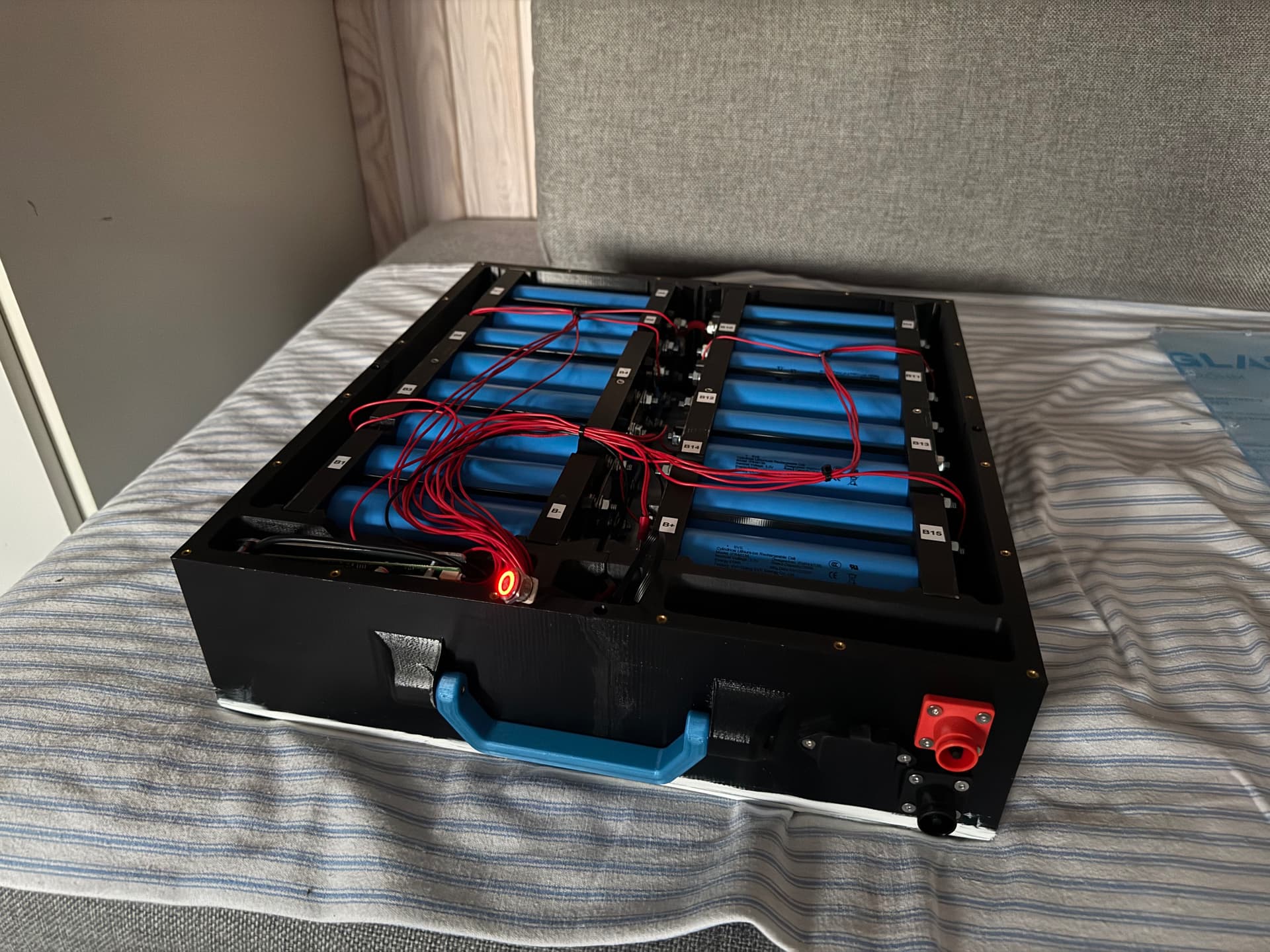
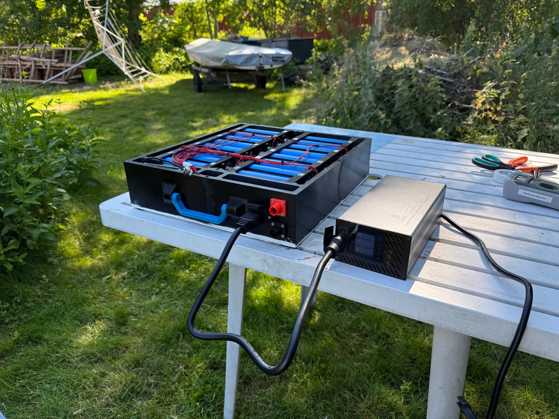
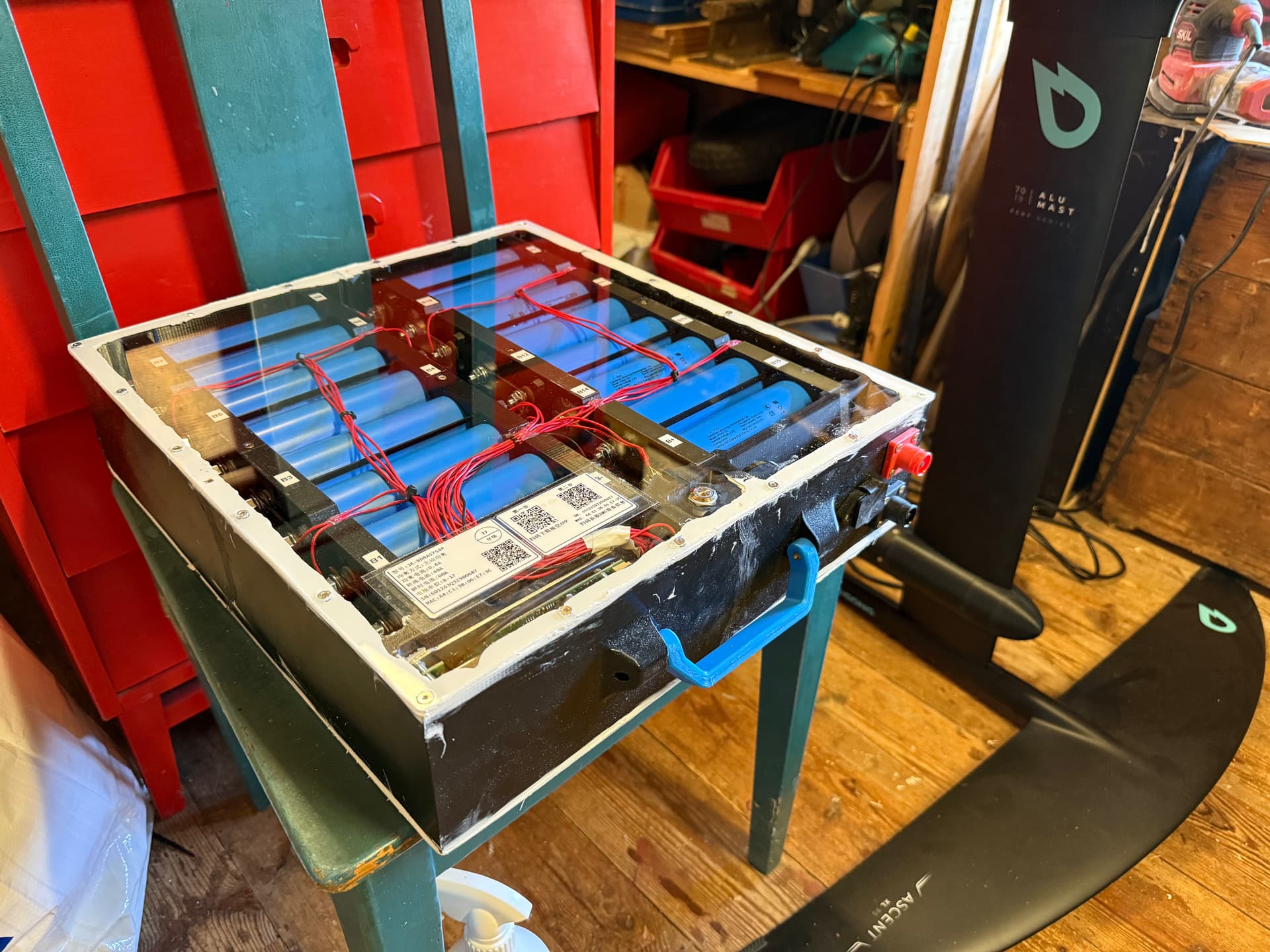
I have designed the battery too. It has 10mm thick printed walls that bolt together, forming a frame. They were spray painted with clear coat to isolate from water intrusion between layers. Two Plexiglas sheets with countersunk holes are secured in the frame with M3 screws and heated inserts. This was sealed with SikaFlex 591 as it should be more modern and UV resistant than 291i. A foldable handle is included as well.
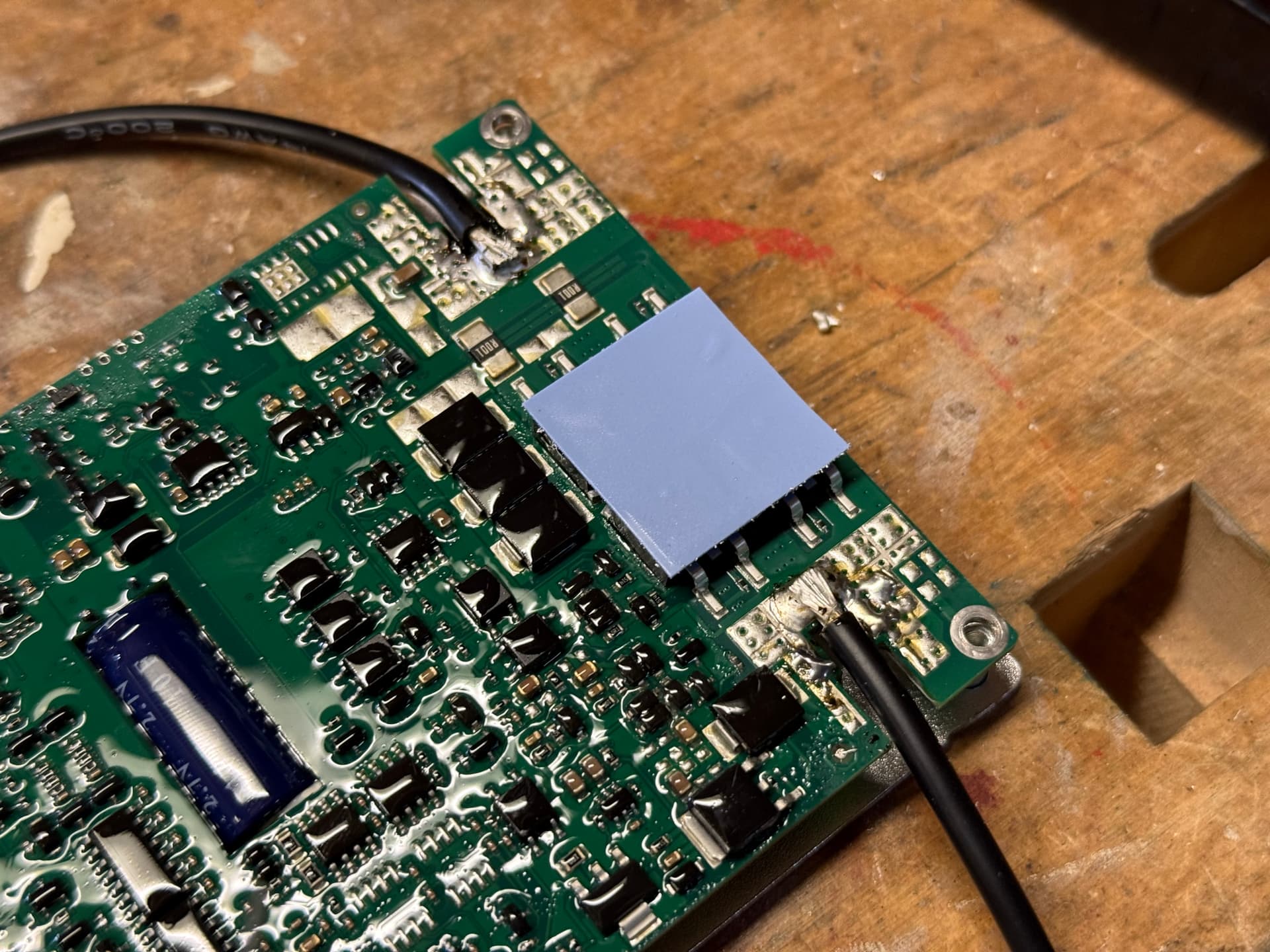
I have made two modular cell packs that simply slot in place along with the BMS. I changed the BMS’s cables for 14 AWG instead of 7 AWG, as it is charge-only.
A formal wiring diagram is not available, so the battery configuration is described below.
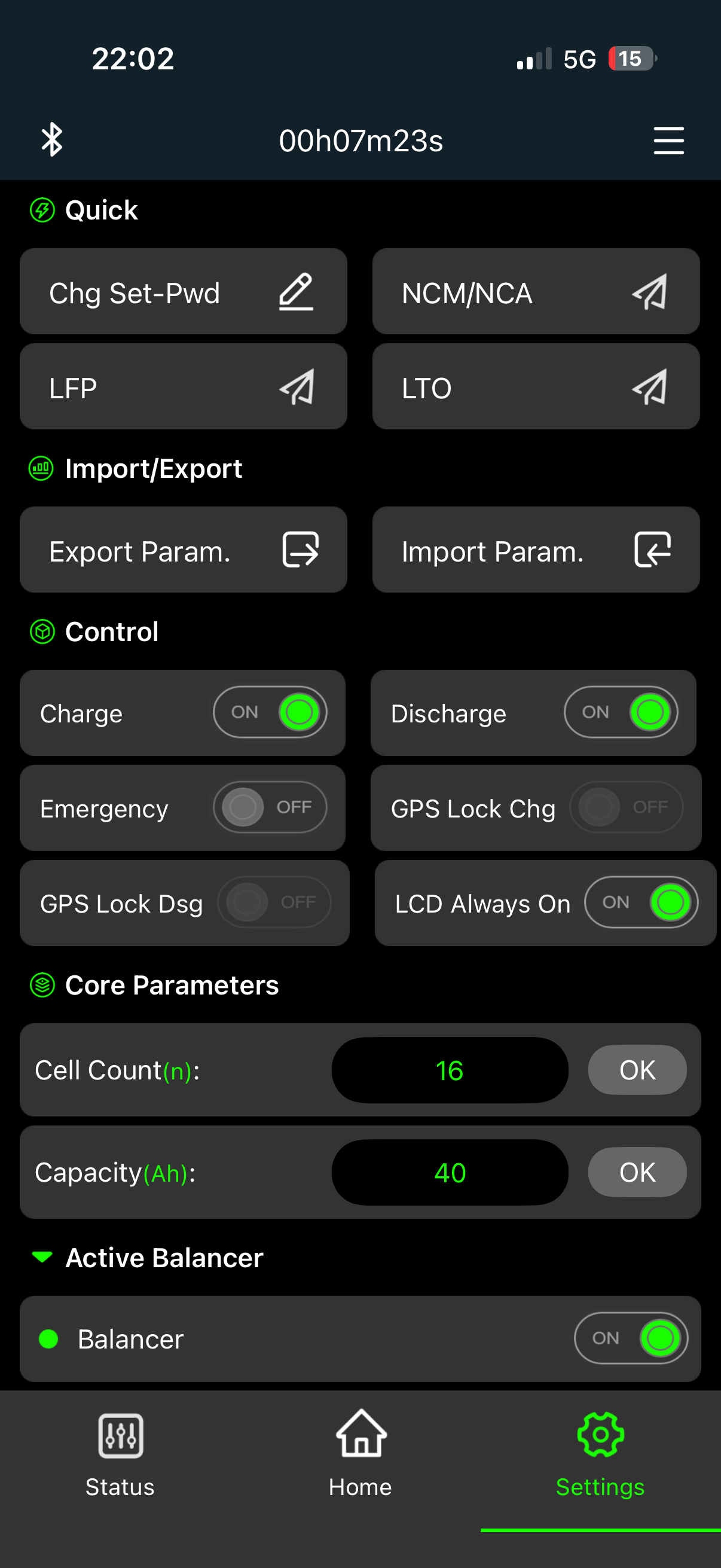
The complete battery pack consists of 32 cells configured as a 16S2P pack. The cells are physically arranged as two 16-cell packs positioned side by side (left and right). Two different wiring approaches were considered for connecting these packs.
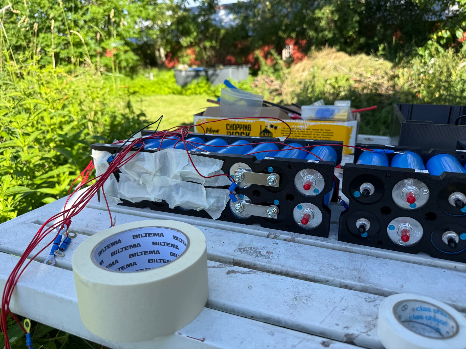
The first approach was to wire the left and right 16-cell packs independently in series (16S) and then connect the two completed packs in parallel. While electrically equivalent, this arrangement would have complicated the BMS wiring, as each balance lead would have needed to be connected to the corresponding voltage node on both 16S packs.
Instead, the implemented configuration connects the corresponding cells of the left and right packs in parallel at each series position, forming sixteen 2P cell groups. These parallel groups are then connected in series to create the final 16S2P battery pack. This arrangement allows each BMS balance lead to connect to a single series node, resulting in a significantly simpler and cleaner wiring layout while maintaining the same electrical configuration.
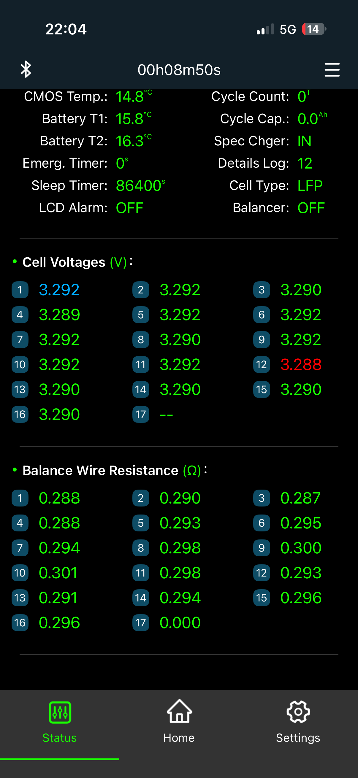
The two temperature probes are inserted in the middle of the packs.
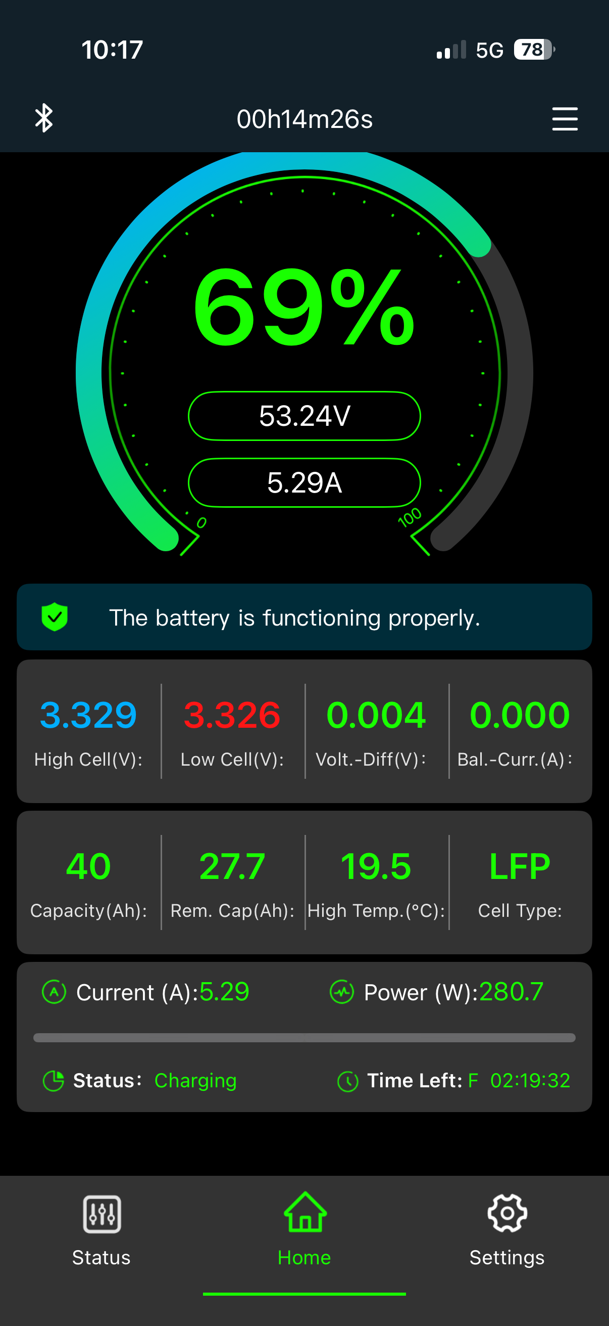
I really like JIKONG’s app. I use the one called “JK BMS”. I took some screenshots of the first charge test.
I stress tested 20A charging (1168W) successfully too, even though the 14 AWG cables warmed up slightly.
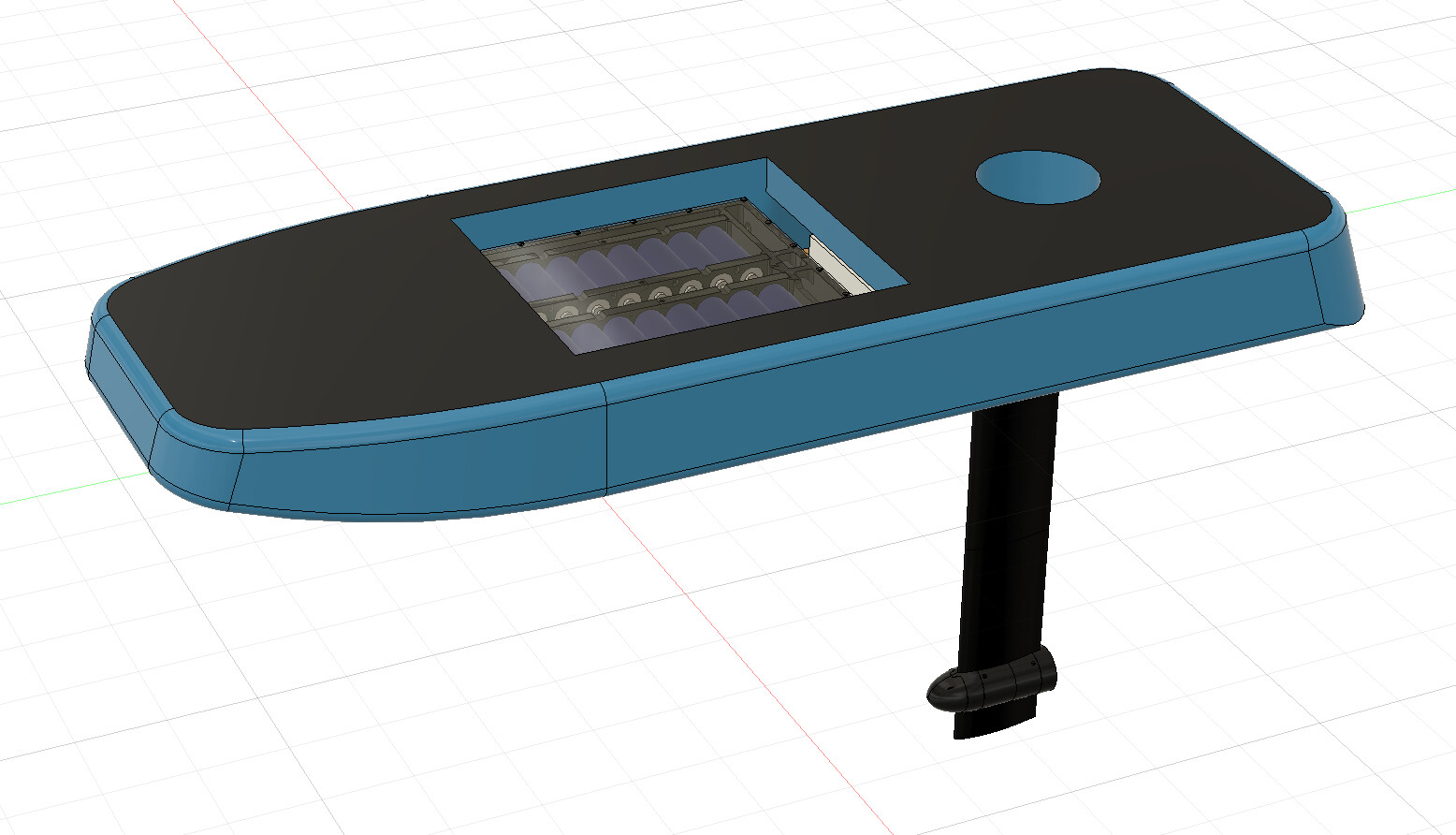
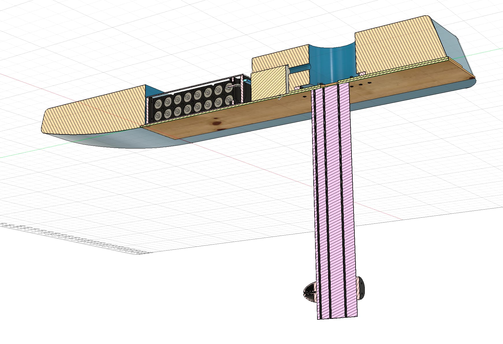
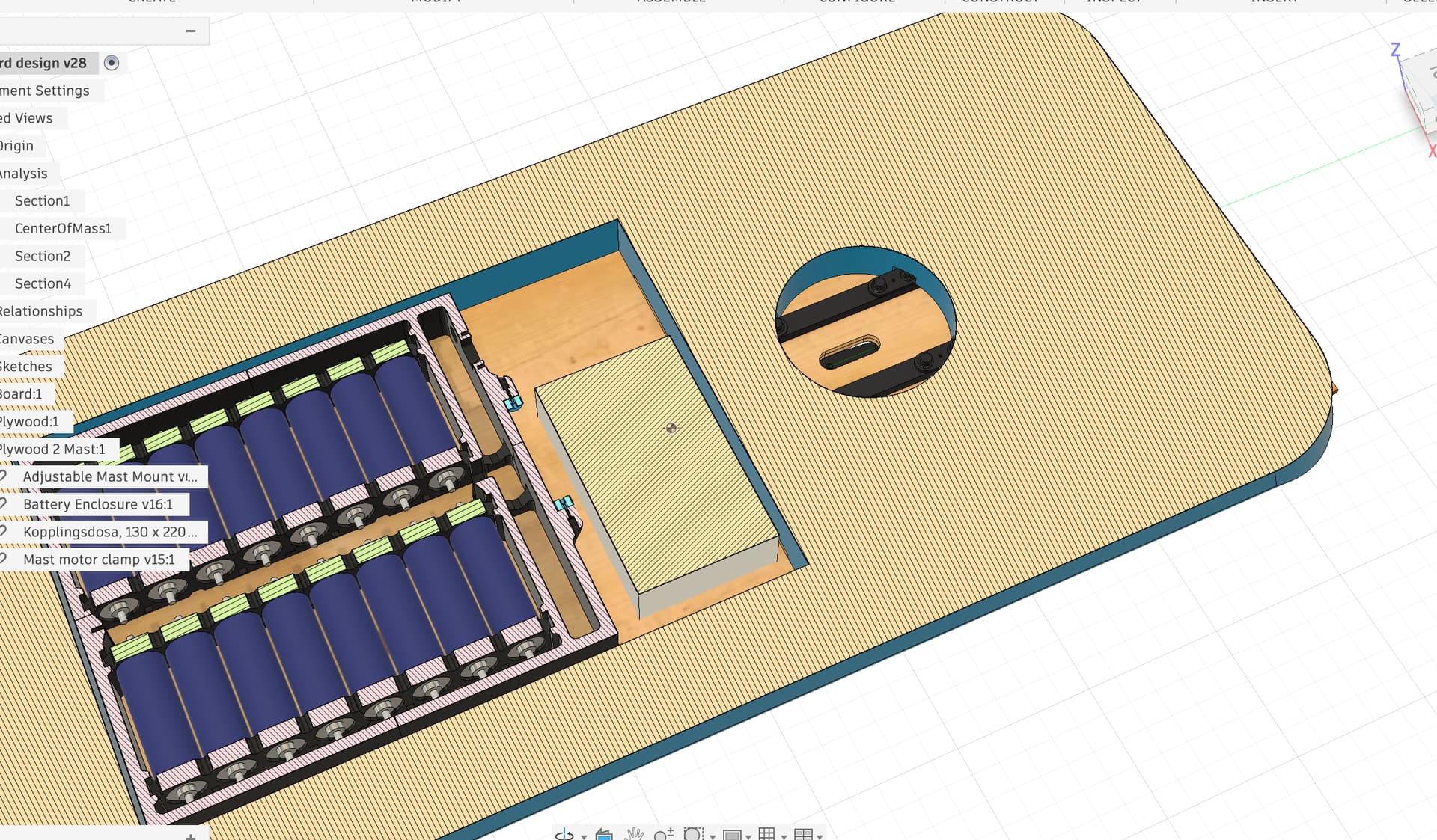
Complete CAD assembly.
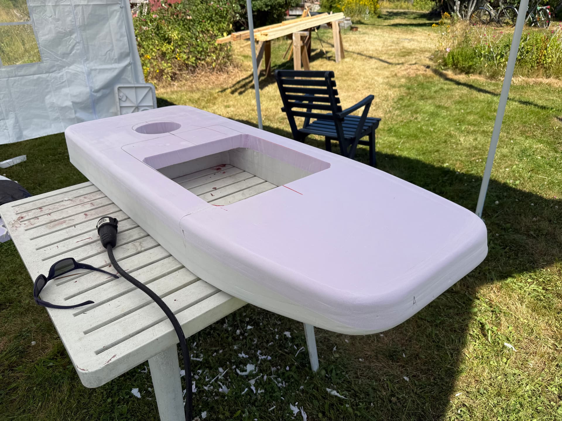
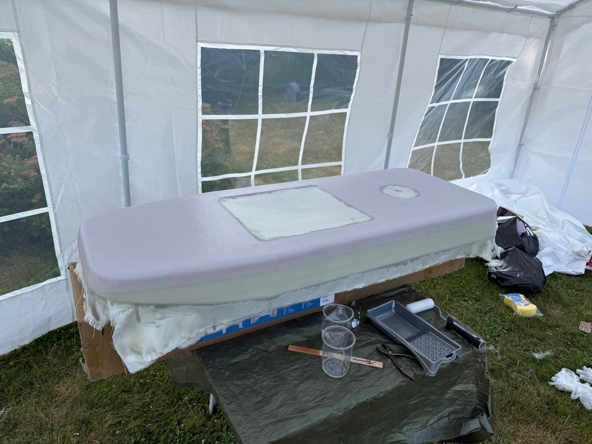
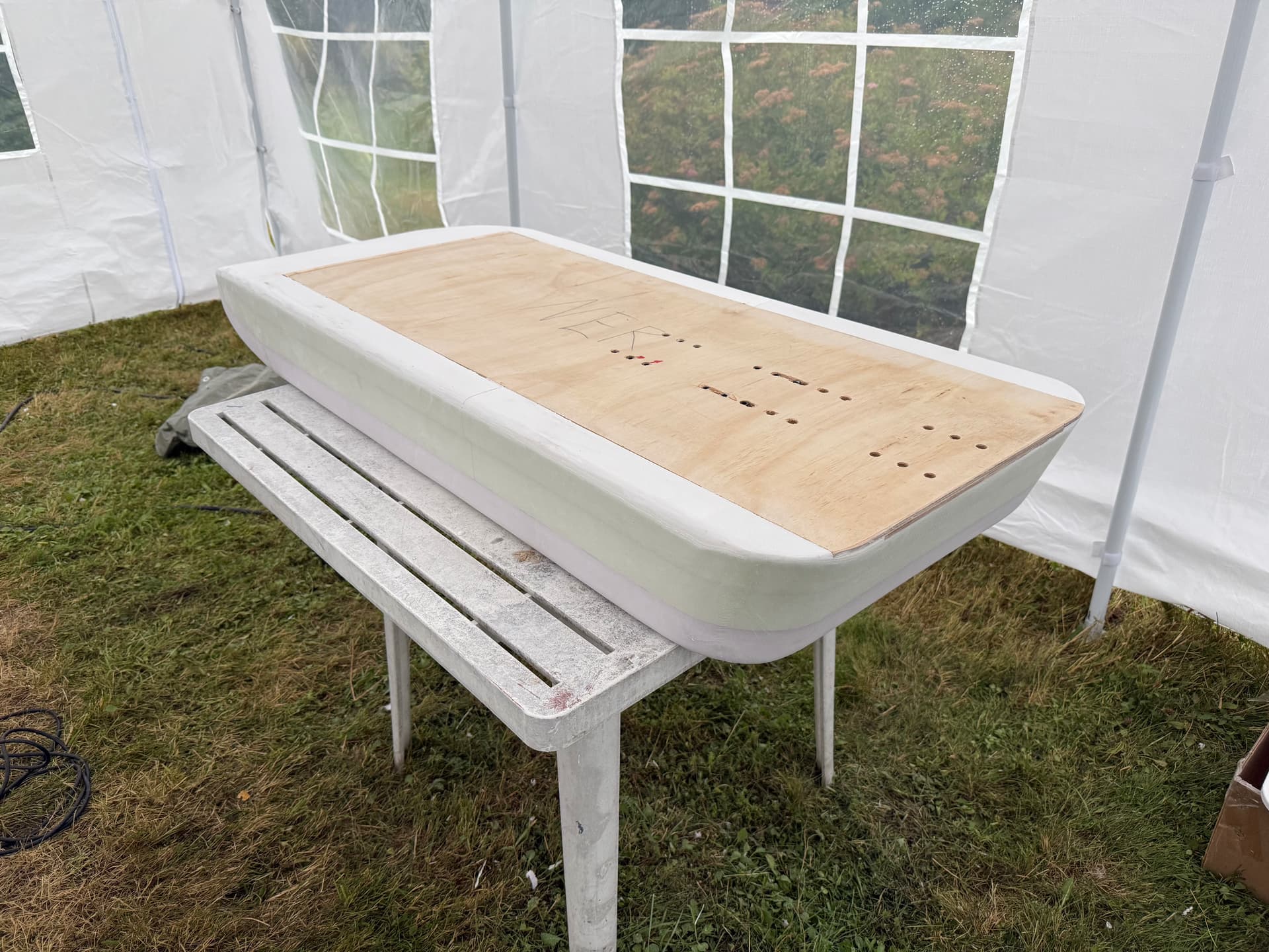
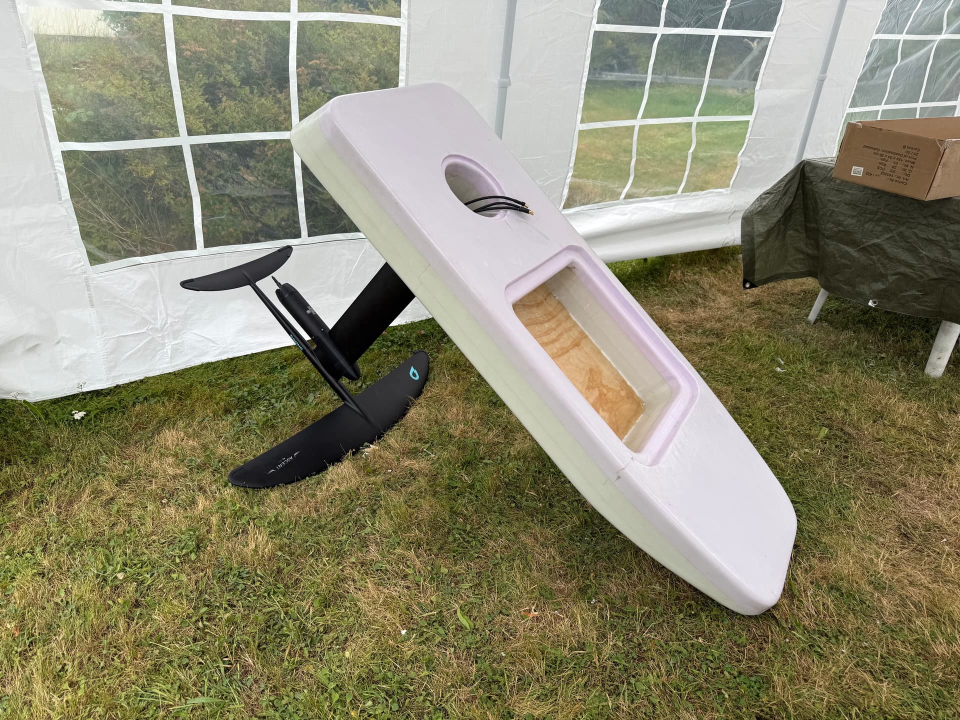
Board was cut out with the hot wire cutter and a multitool, and then sanded.
I laminated the top and sides of the board with two layers of 300g/m2 fiberglass weave and epoxy.
2 Likes
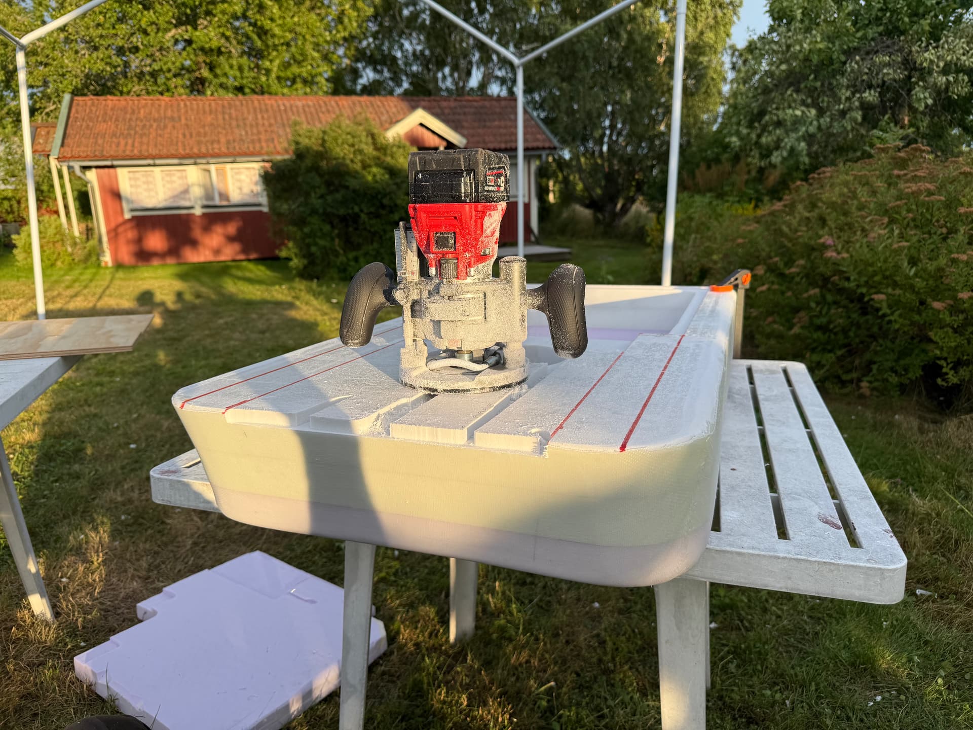
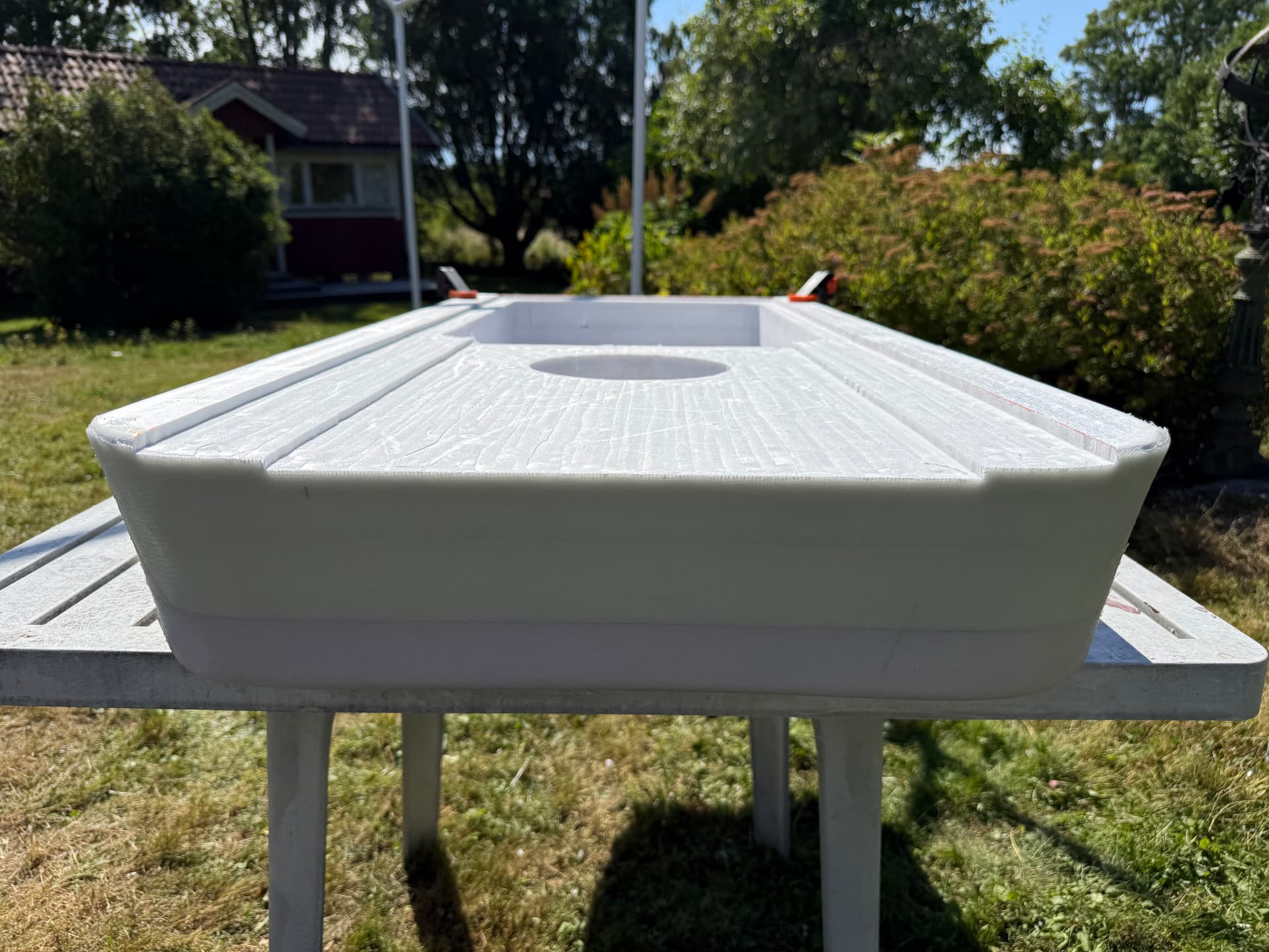
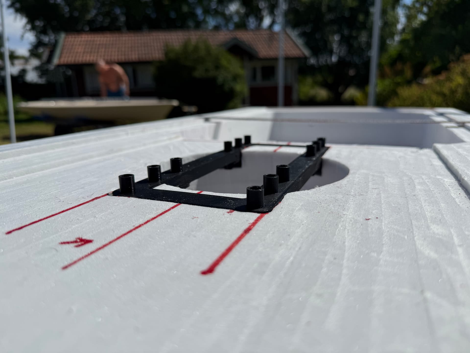
Next step was milling where two 5,5mm plywood boards and the mast nut holder will be attached.
I glued everything in place with polyurethane glue.
The inside was laminated with one layer weave.
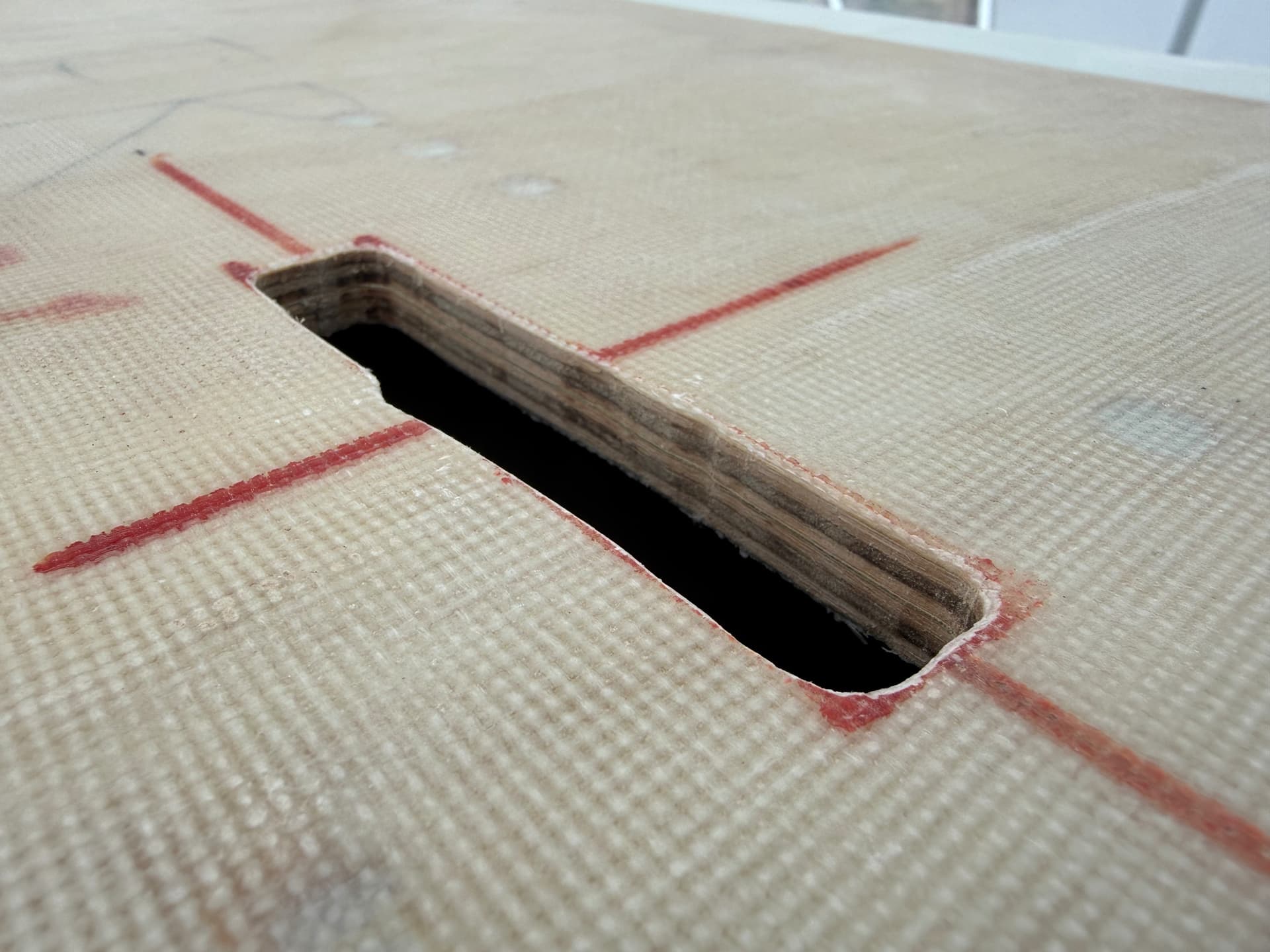
The underside got two layers of weave, and an extra layer where the mast connects.
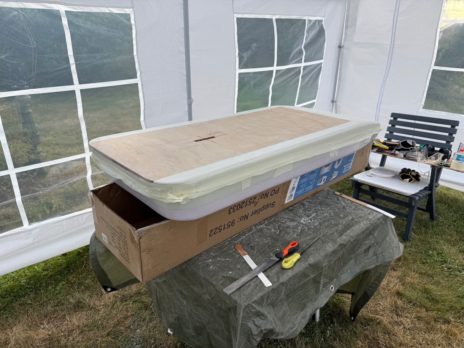
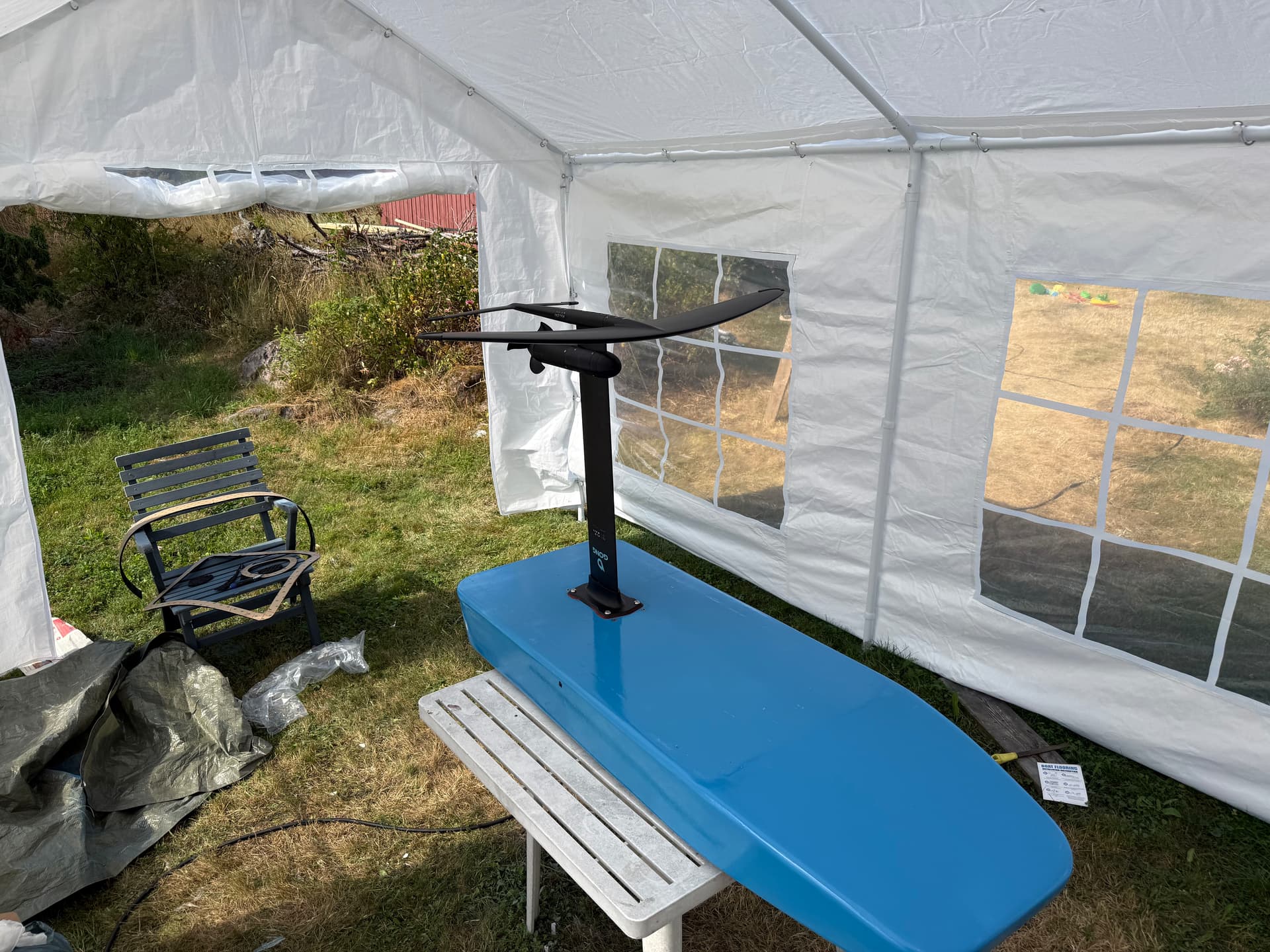
Test fit.
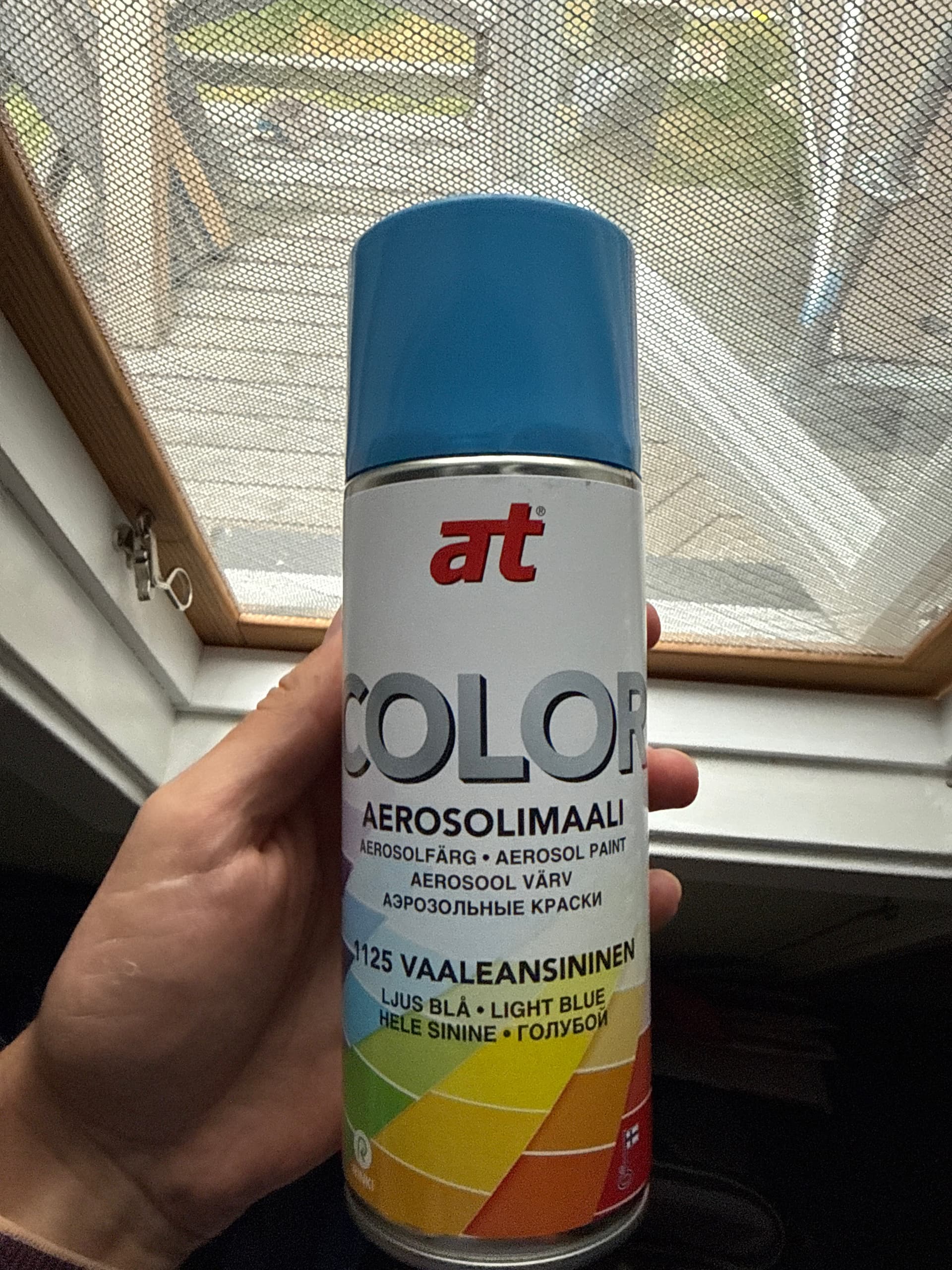
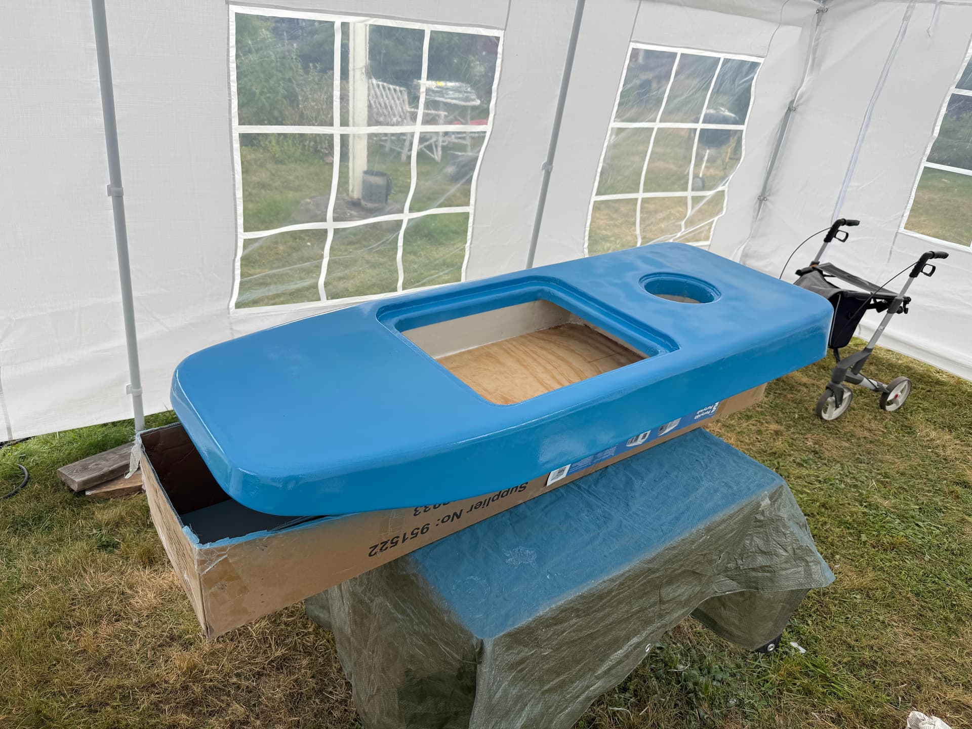
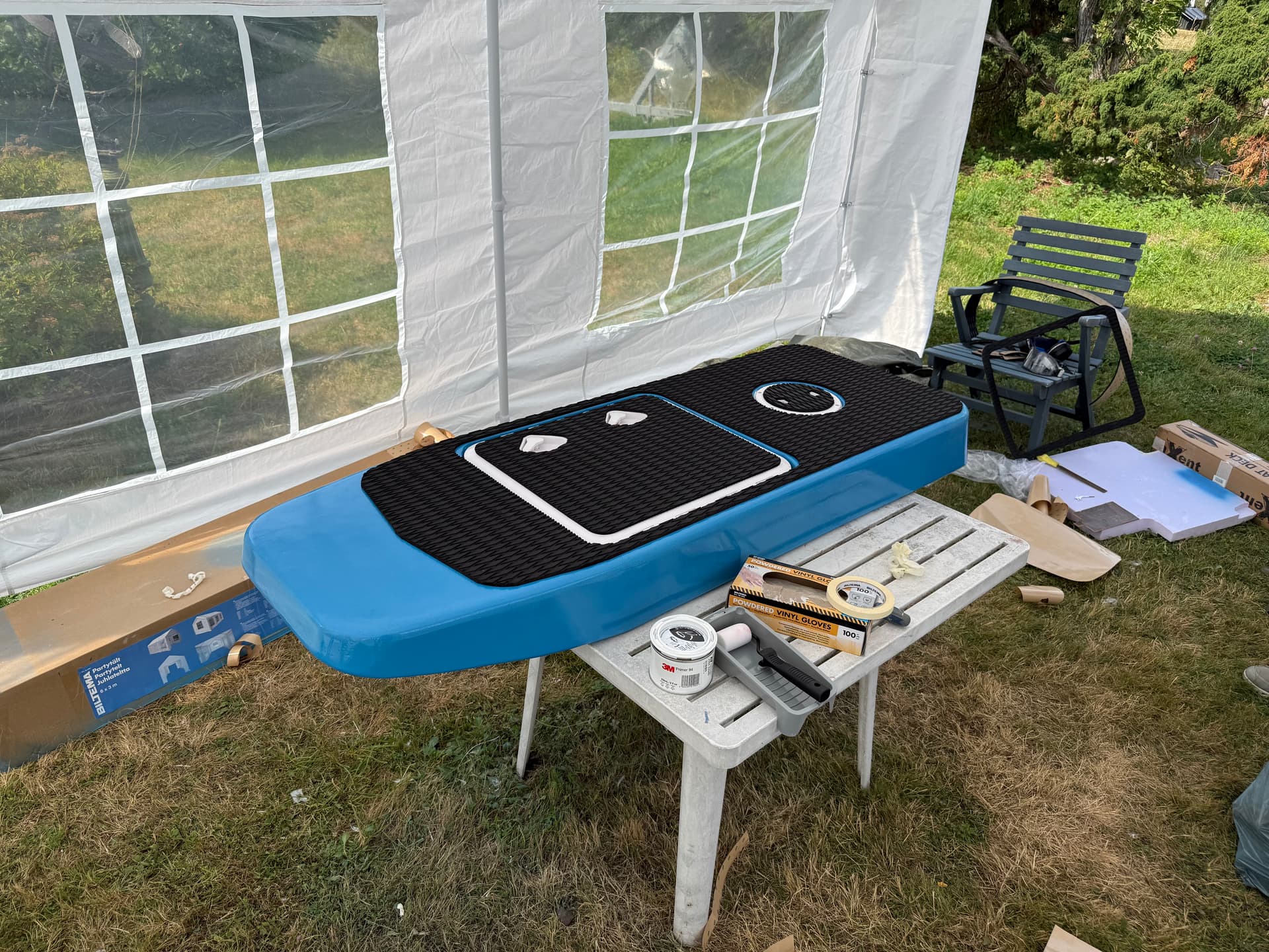
I went with light blue. It took 3 cans of color and 3 cans of clear coat for the whole board.
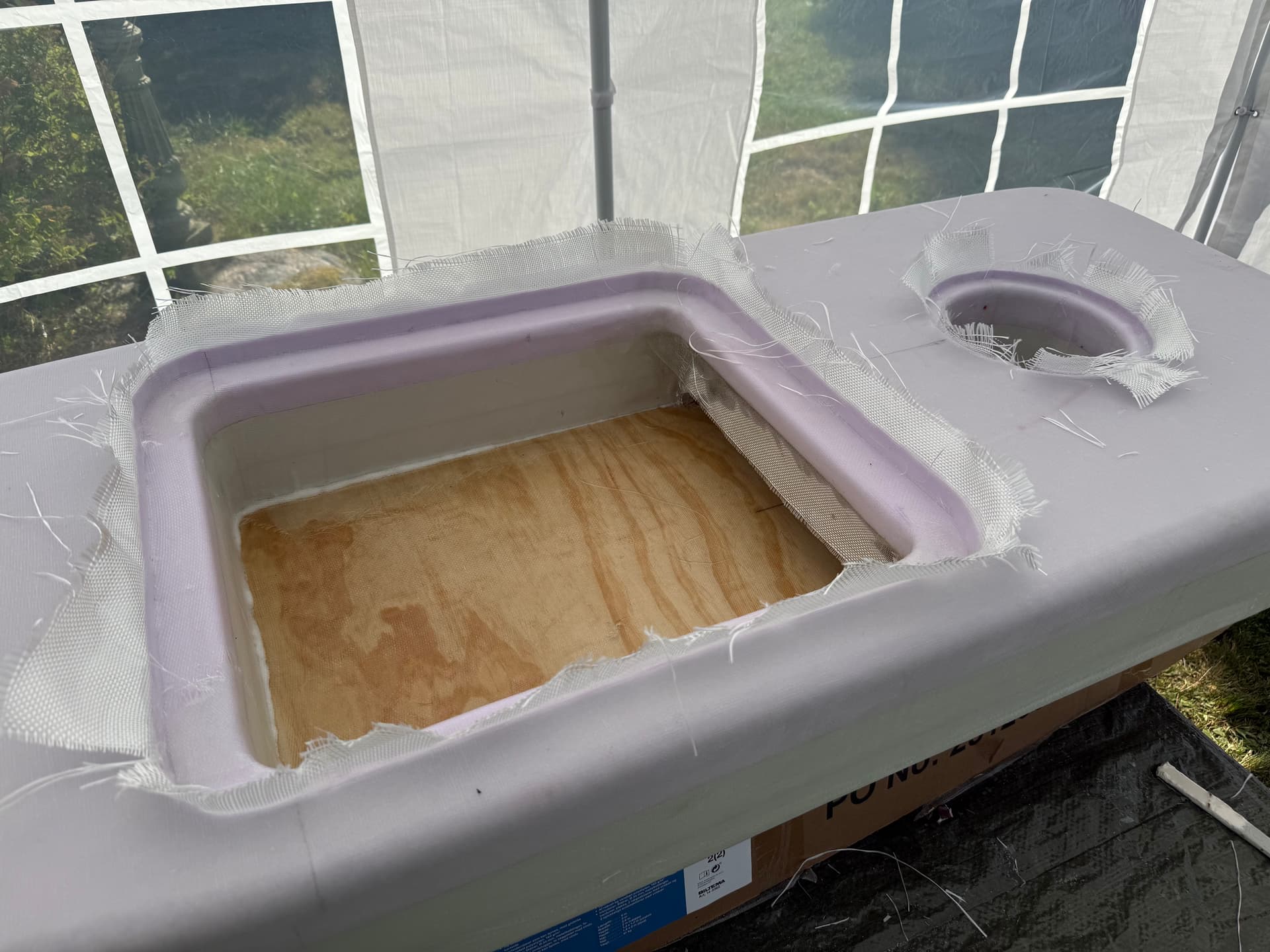
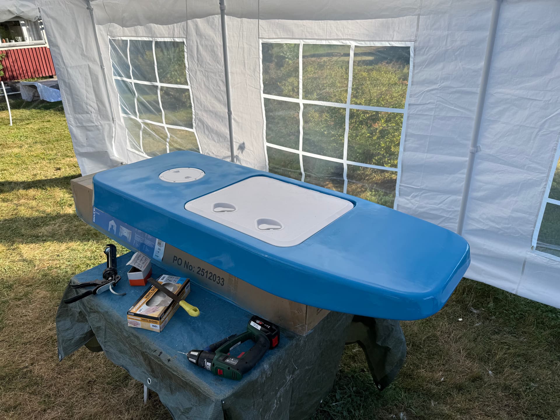
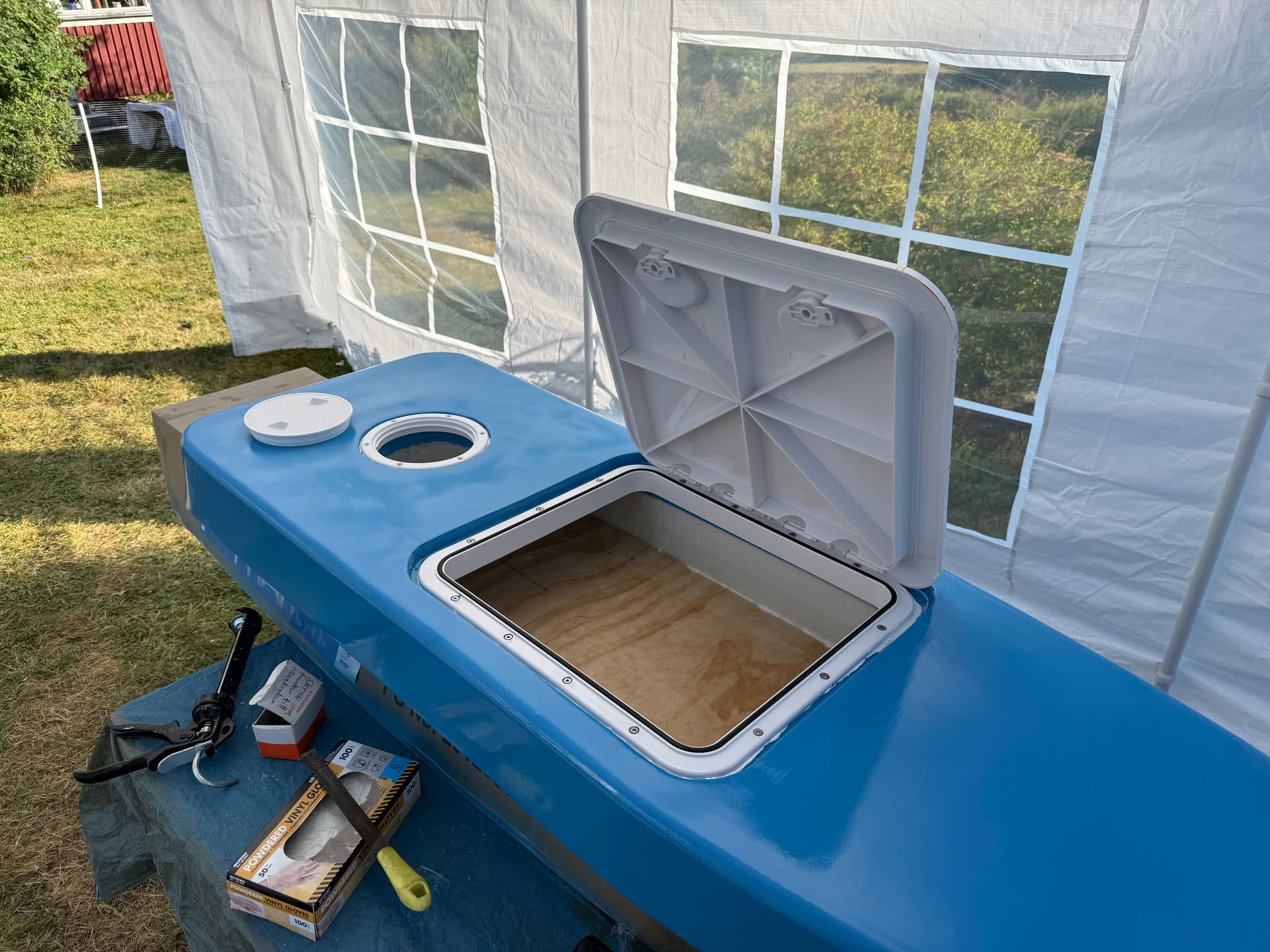
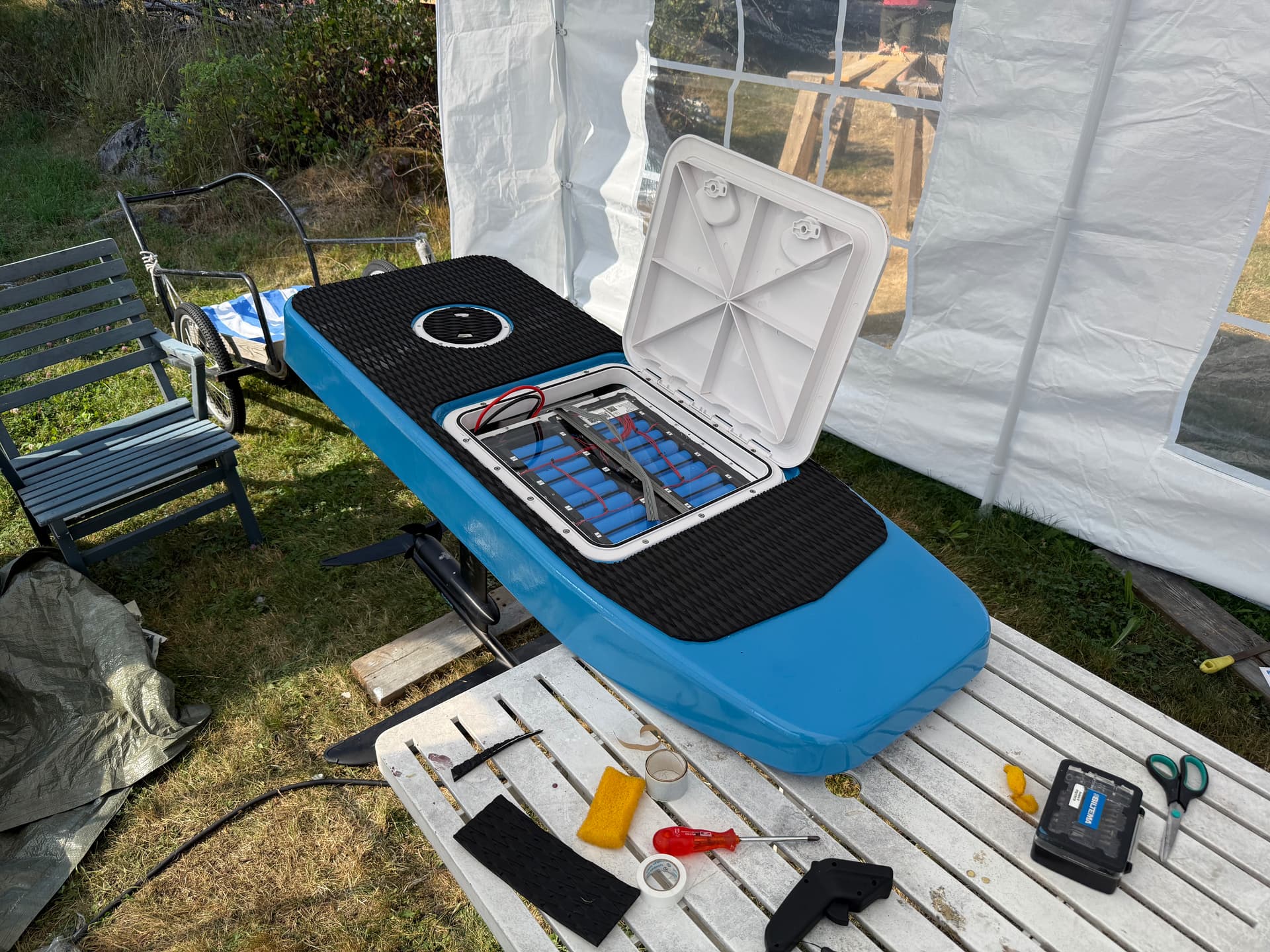
Hatch was installed with lots of SikaFlex and stainless wood screws.
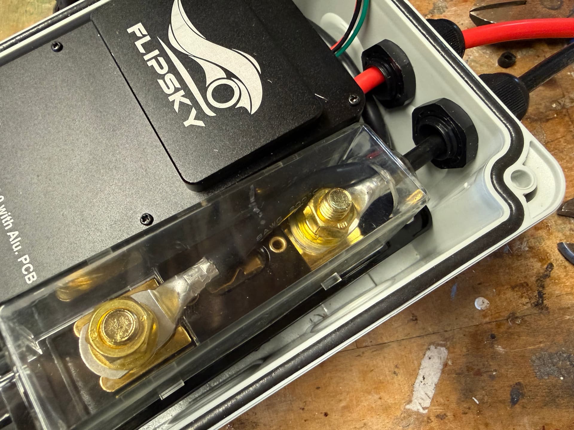
I wired a 200A fuse between the battery and ESC.
The 8AWG wires were difficult to solder, but I think it turned out ok.
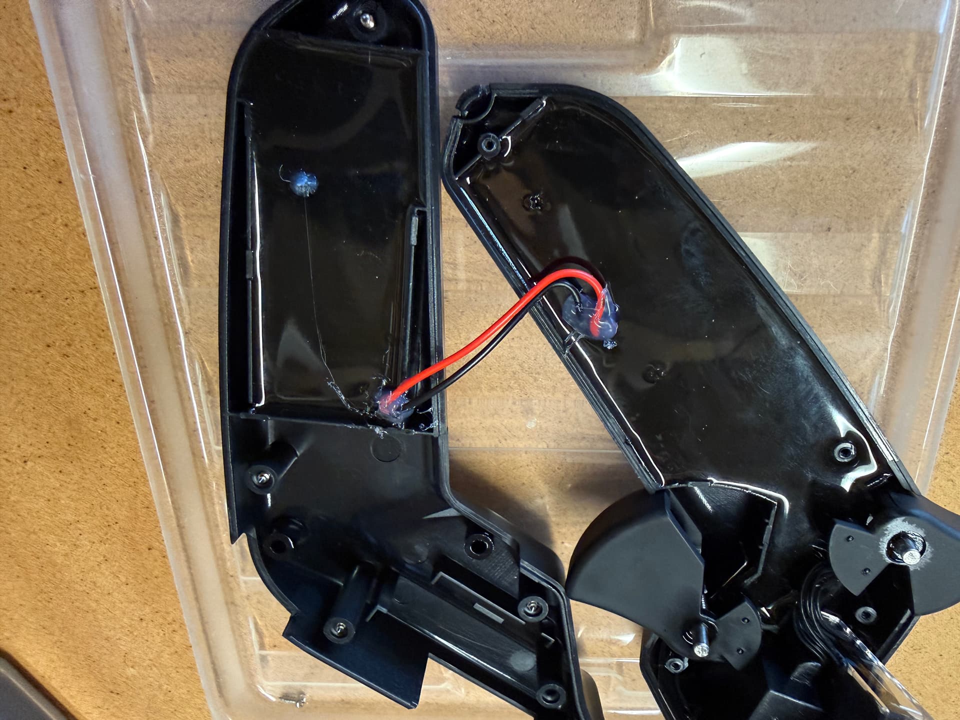
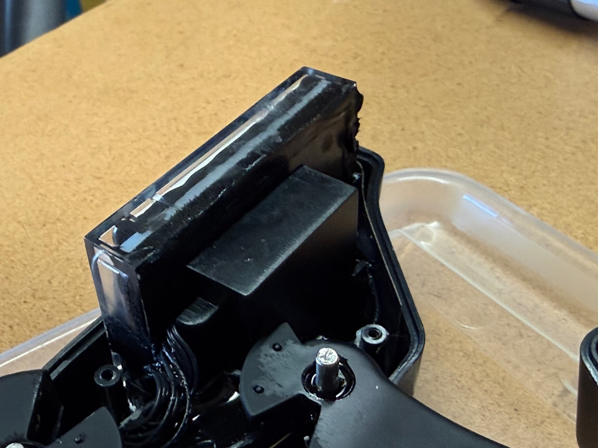
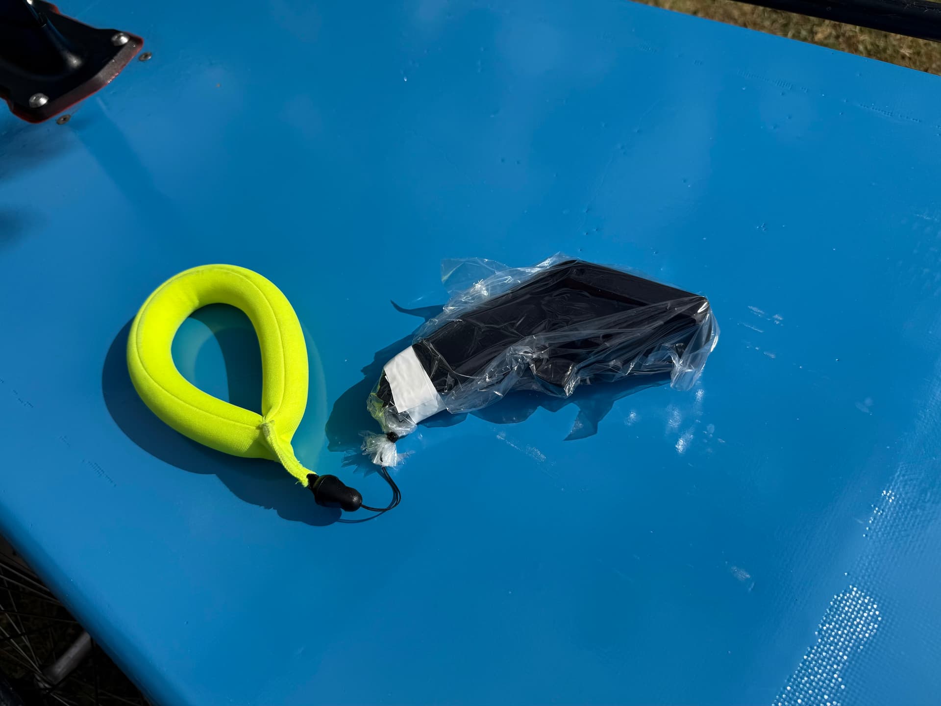
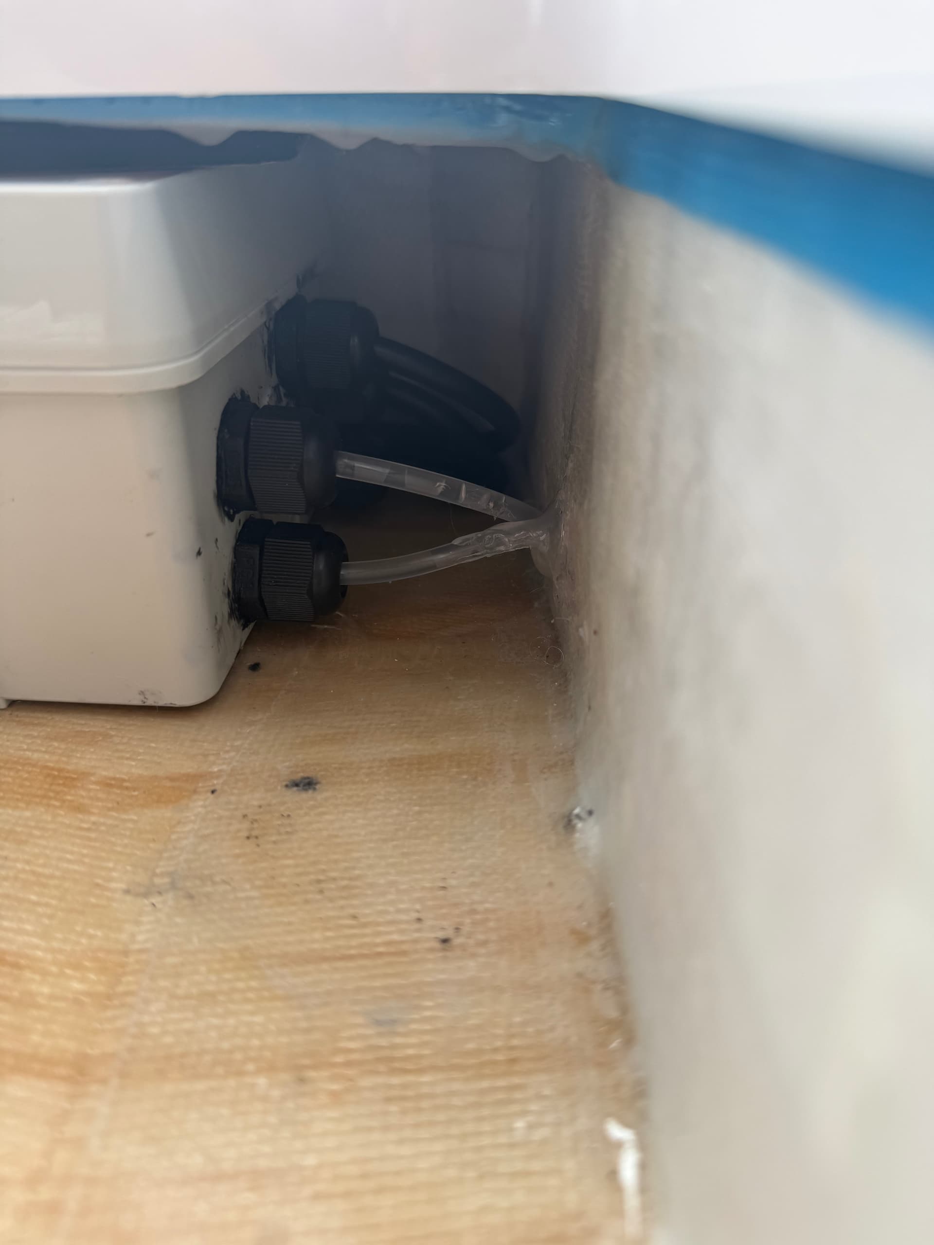
I have read some bad reviews about the VX3 so I did some waterproofing around the cables with hot glue, and around the screen enclosure with SikaFlex 291i. I’m not sure if the plastic bag is necessary though. I will order the VX5 once this breaks.
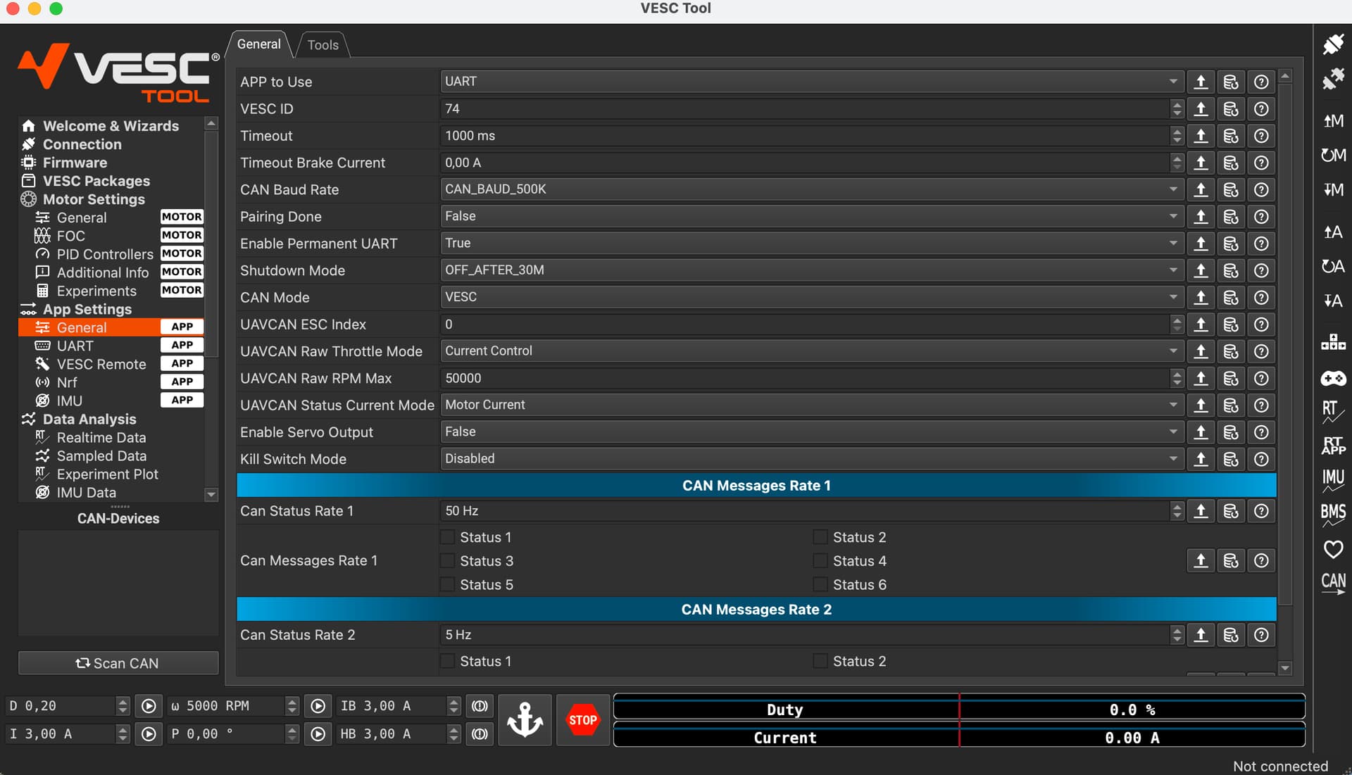
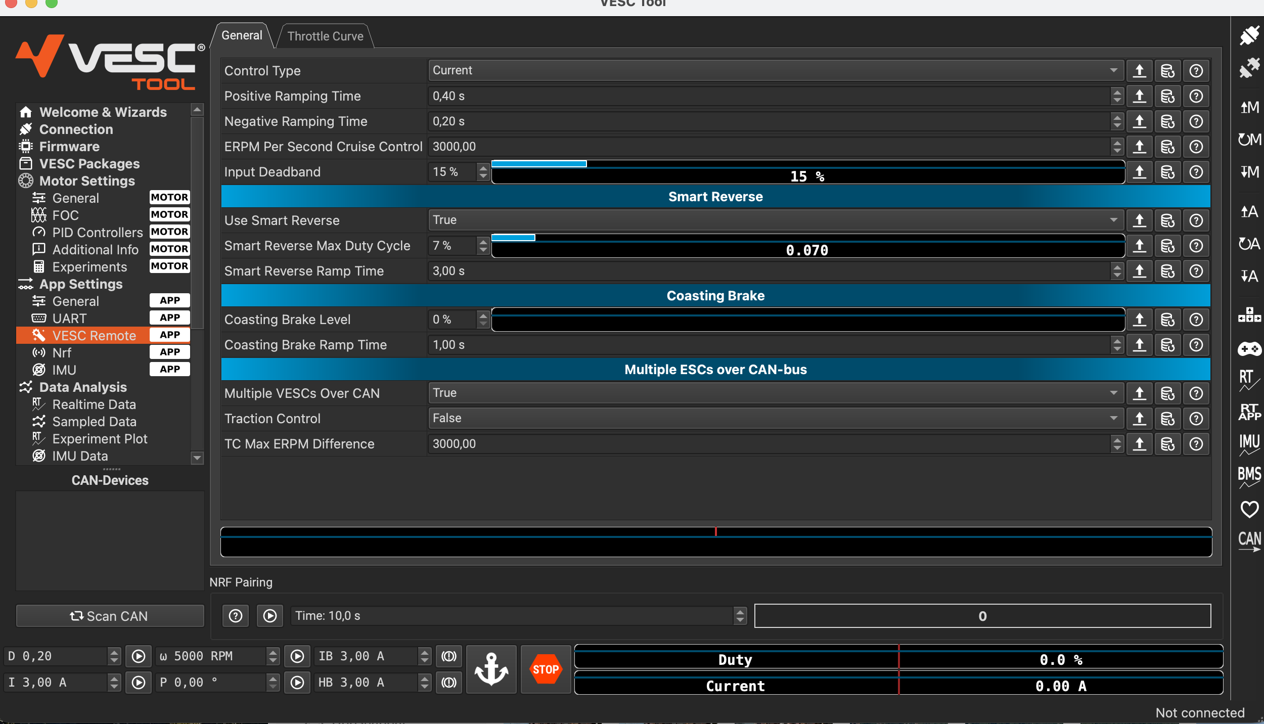
I followed Ludwig Bre’s video on VESC configuration. It was very good, but I had difficulties to set up my VX3 remote. The PPM protocol worked initially for motor control, but as it does not support telemetry, I chose UART. The screenshots below show what settings worked for me.
At first, telemetry worked, but not throttle. I had to select “Current” instead of “Off” in App Settings → VESC Remote → Control Type.
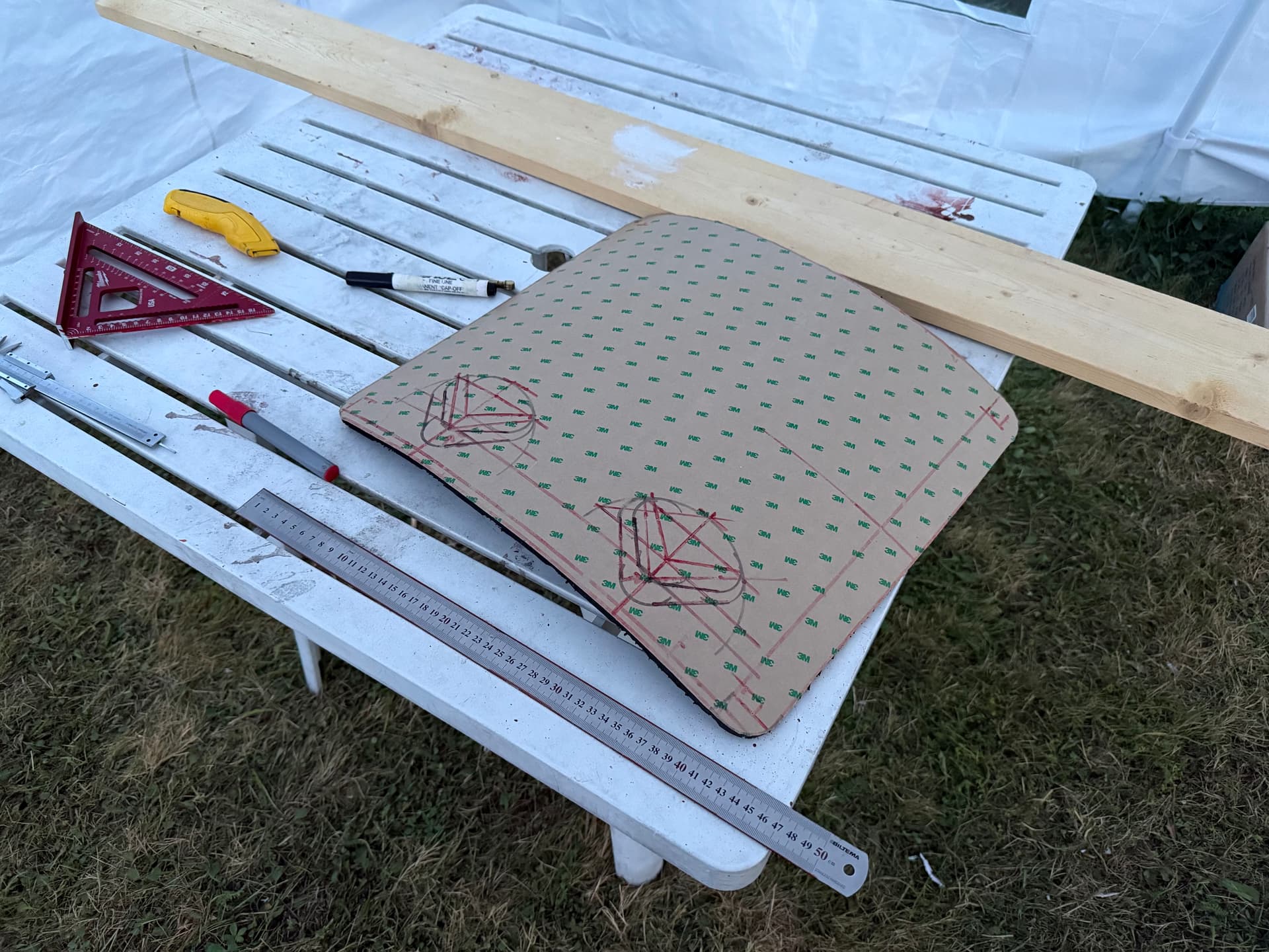
I installed EVA boat deck foam with 3M primer 94.
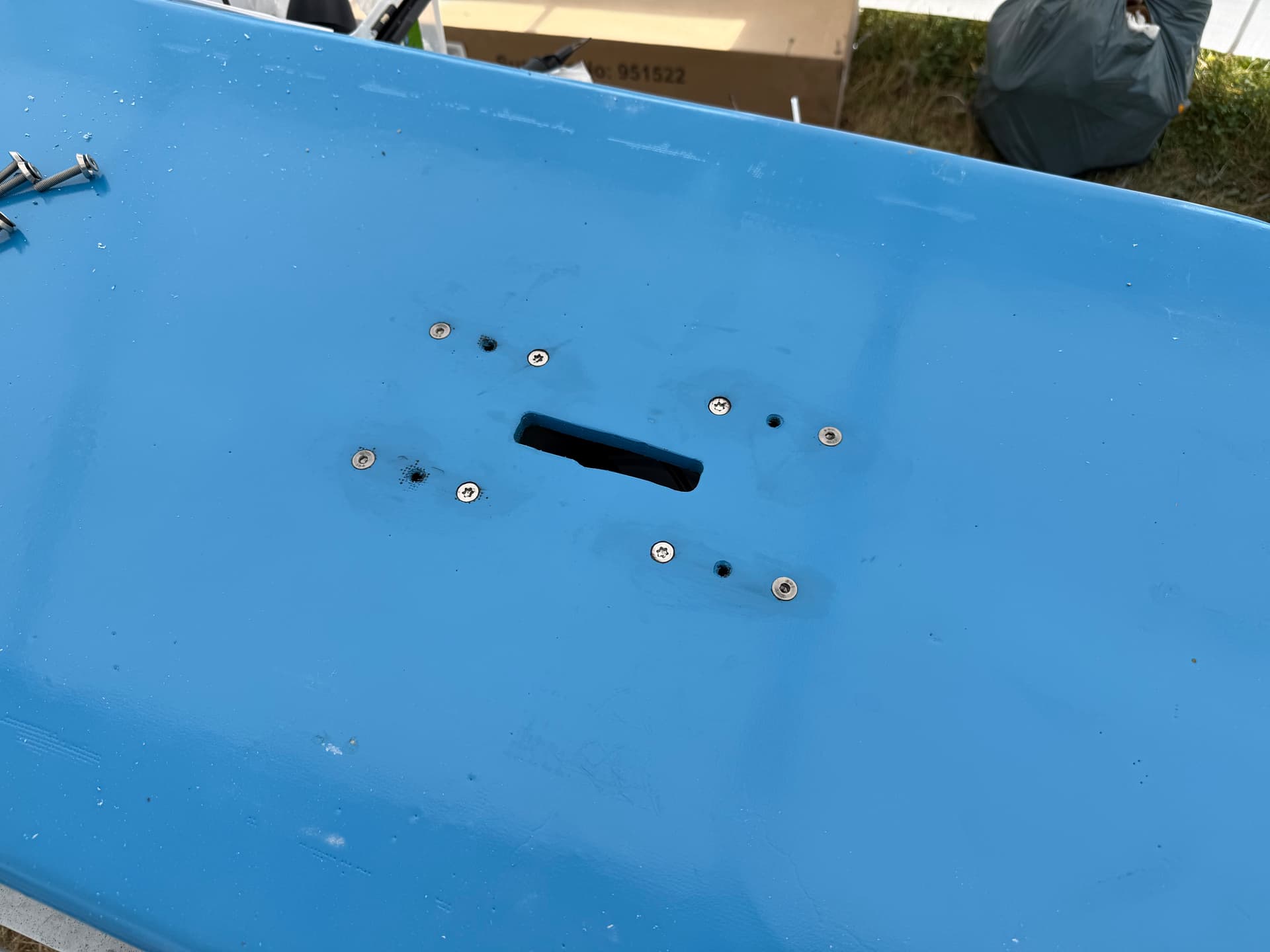
I put some shorter M6 screws sealed with SikaFlex 291i in the unused holes.
The water cooling’s outlet is on the side of the board for visibility.
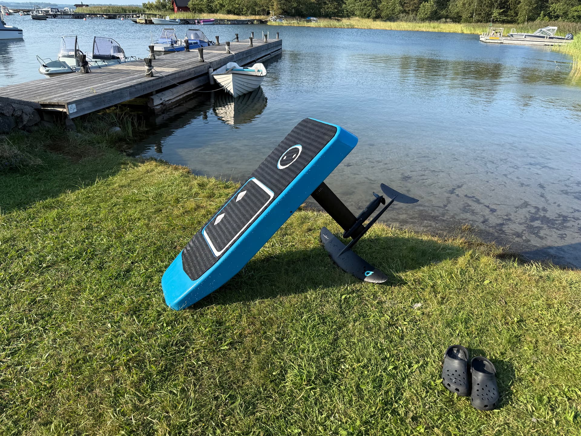
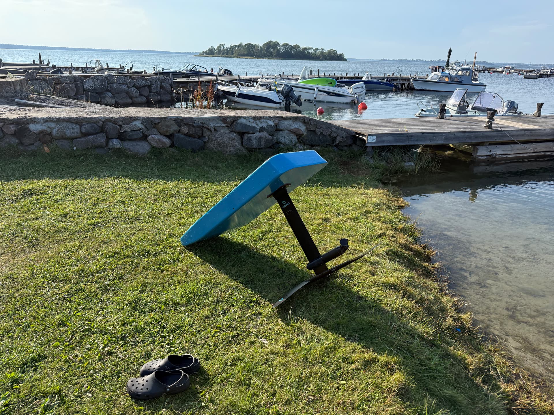
It’s done!!!
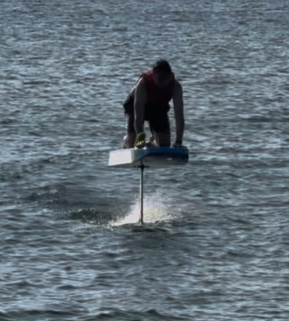
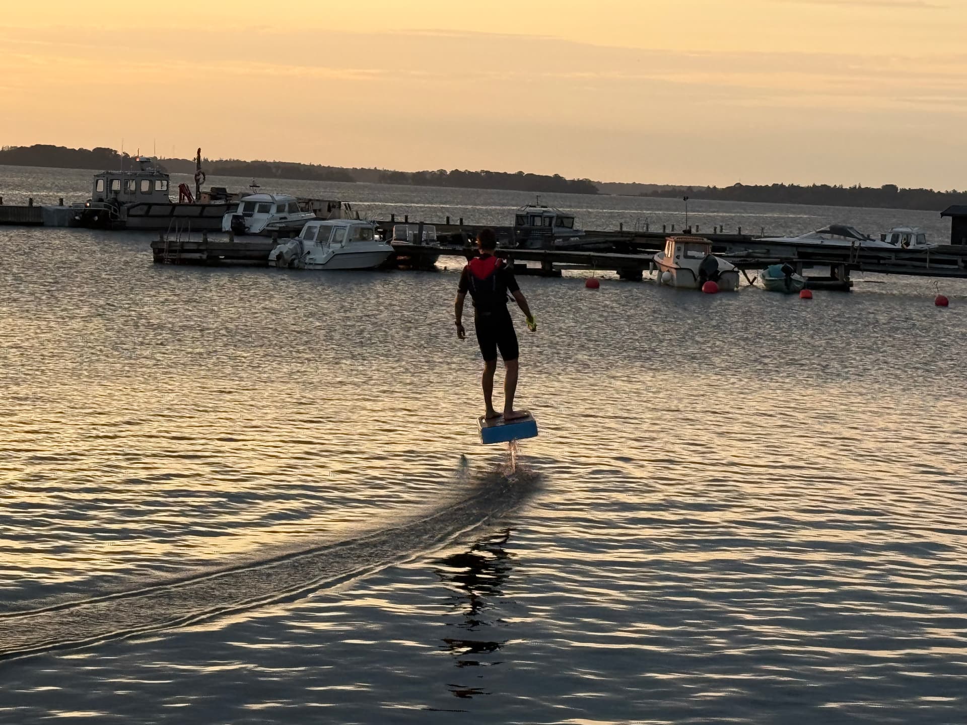
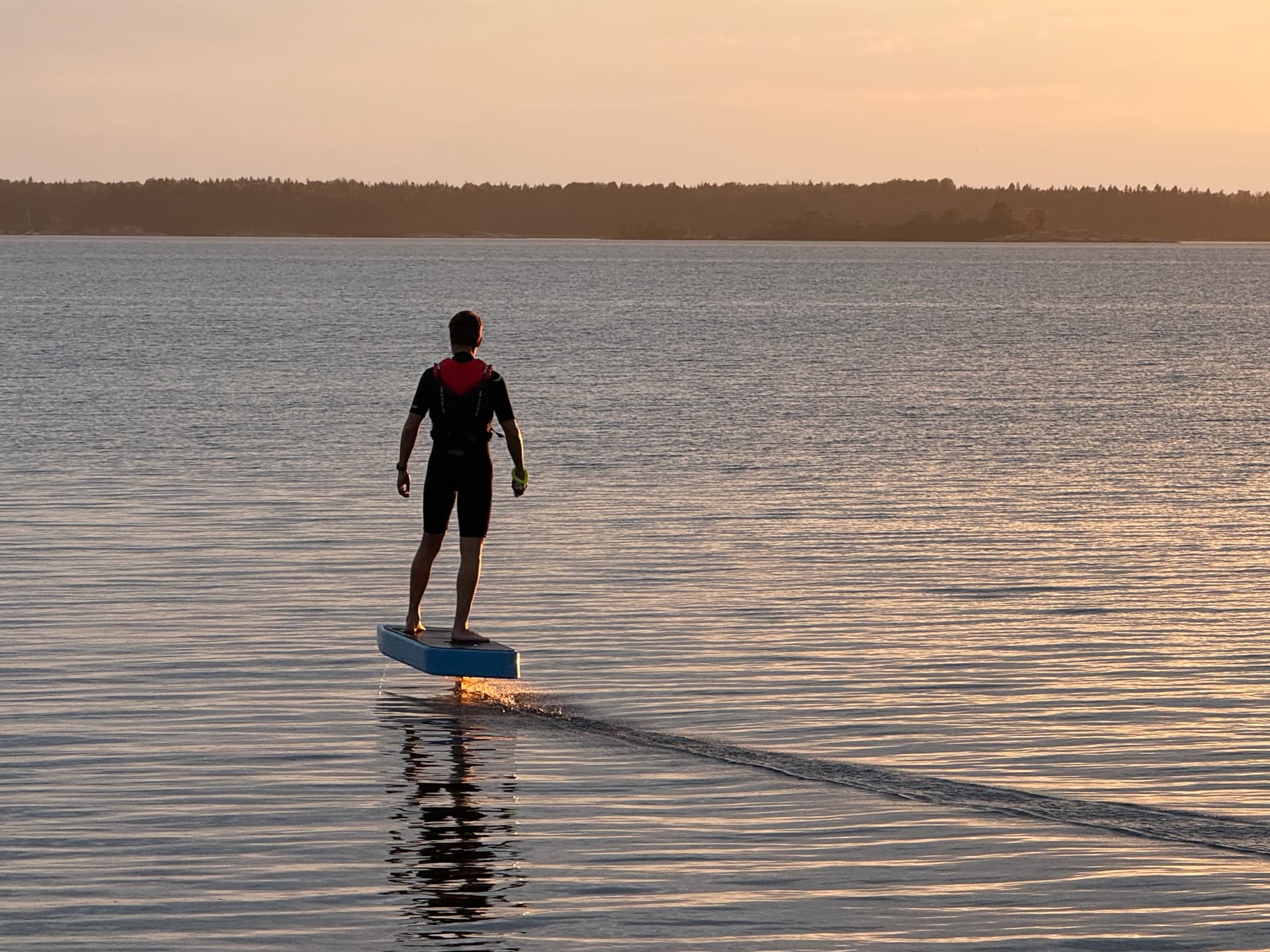
First test ride was really successful. It was completely dry under both hatches. A visible stream of water was coming from the outlet. ESC, motor, and battery temps remained under 30C.
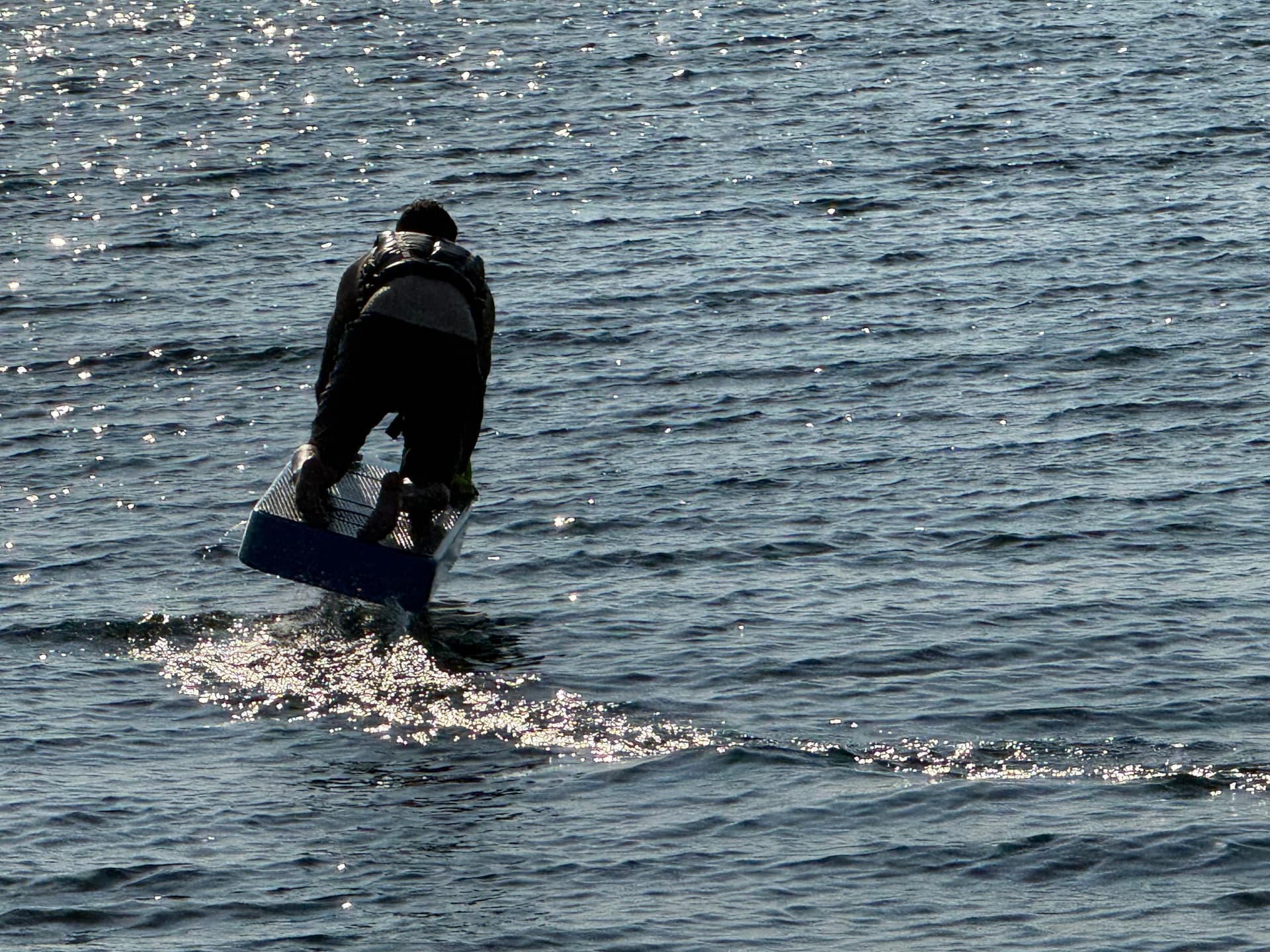
I managed to foil on my knees but standing up is surprisingly difficult. This thing is so much fun!
Total cost was right around 2000 EUR.
4 Likes
Hey UppfinnarAXEL, this is an amazing write-up, great documentation, very inspiring. I was wondering if you had more detailed photos or description of the ESC box and how it is mounted to the mast, and how this rectangular electronics box integrates with the circular porthole in the top of your foam board. Did you manage to use the mast as a heat sink?
Thanks!
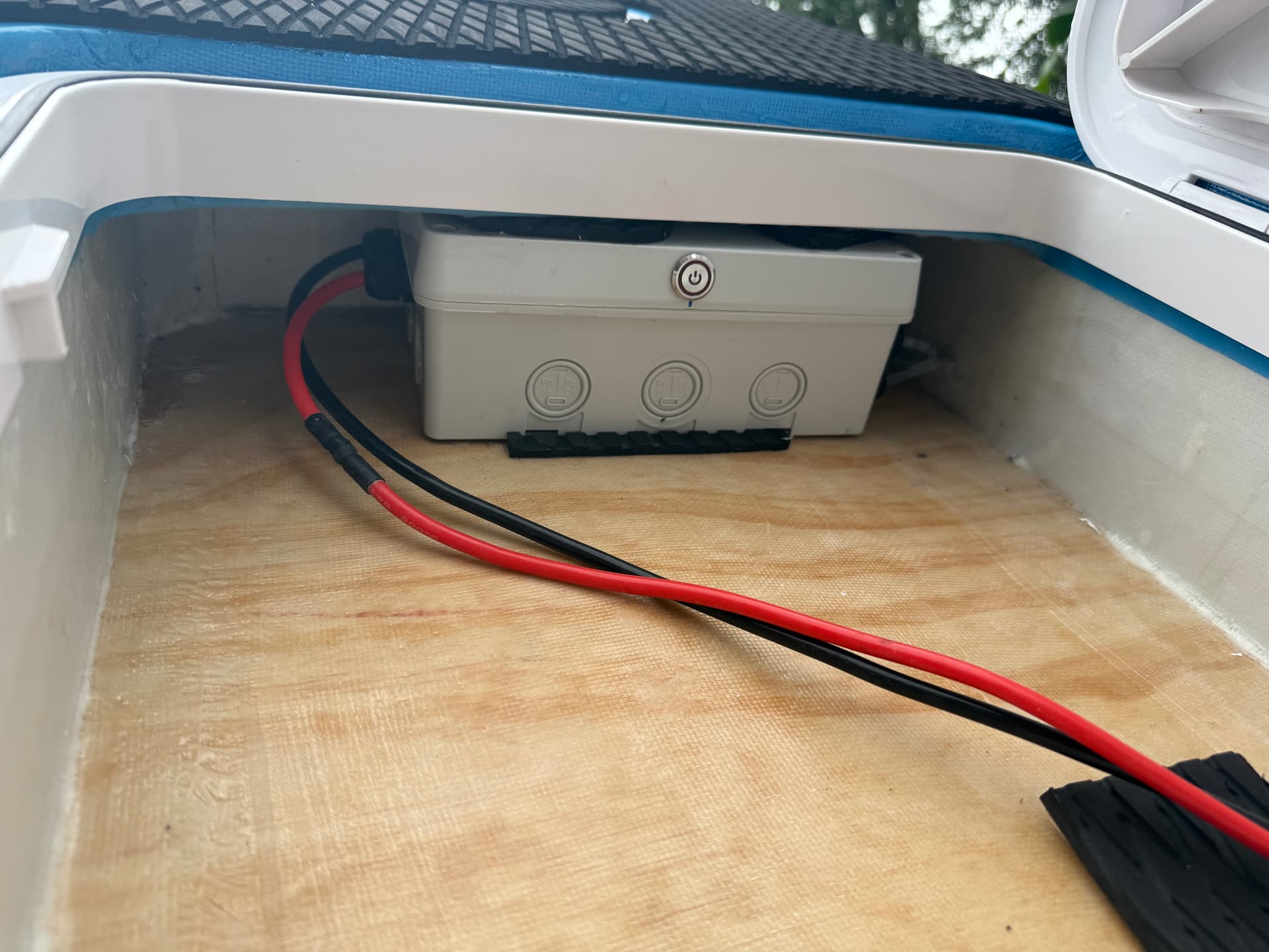
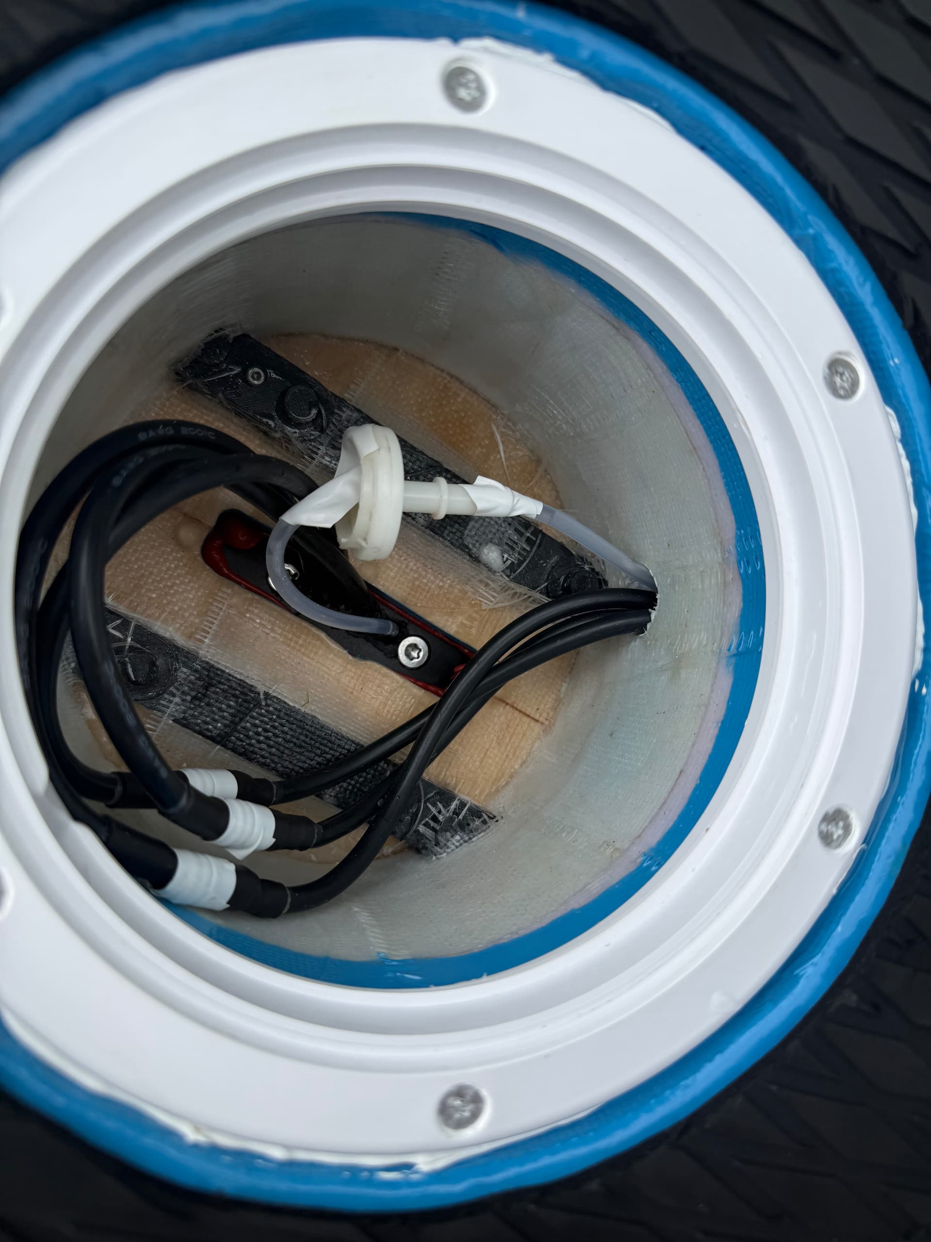
Thanks! The esc box is hidden in a compartment under the rectangular hatch. The round hatch is basically empty, as it’s simply a space for wires coming from the mast. I usually put my phone in there for vesc logging. I use ram water cooling. Water flows up to the vesc when there is enough pressure on the motor pod.
I should also mention why I chose this type of rectangular boat inspection hatch despite advice against them. Following a recommendation from another Swedish build, I opted for SeaFlo. They are thicker and stiffer than generic options on Amazon. It prevents deck flex and distorting the waterproof seal.
Legend! Thank you for that rundown, and for sharing your files on Printables. Very interesting cooling method. Keen to see how you go learning the board. Thank you kindly!
1 Like
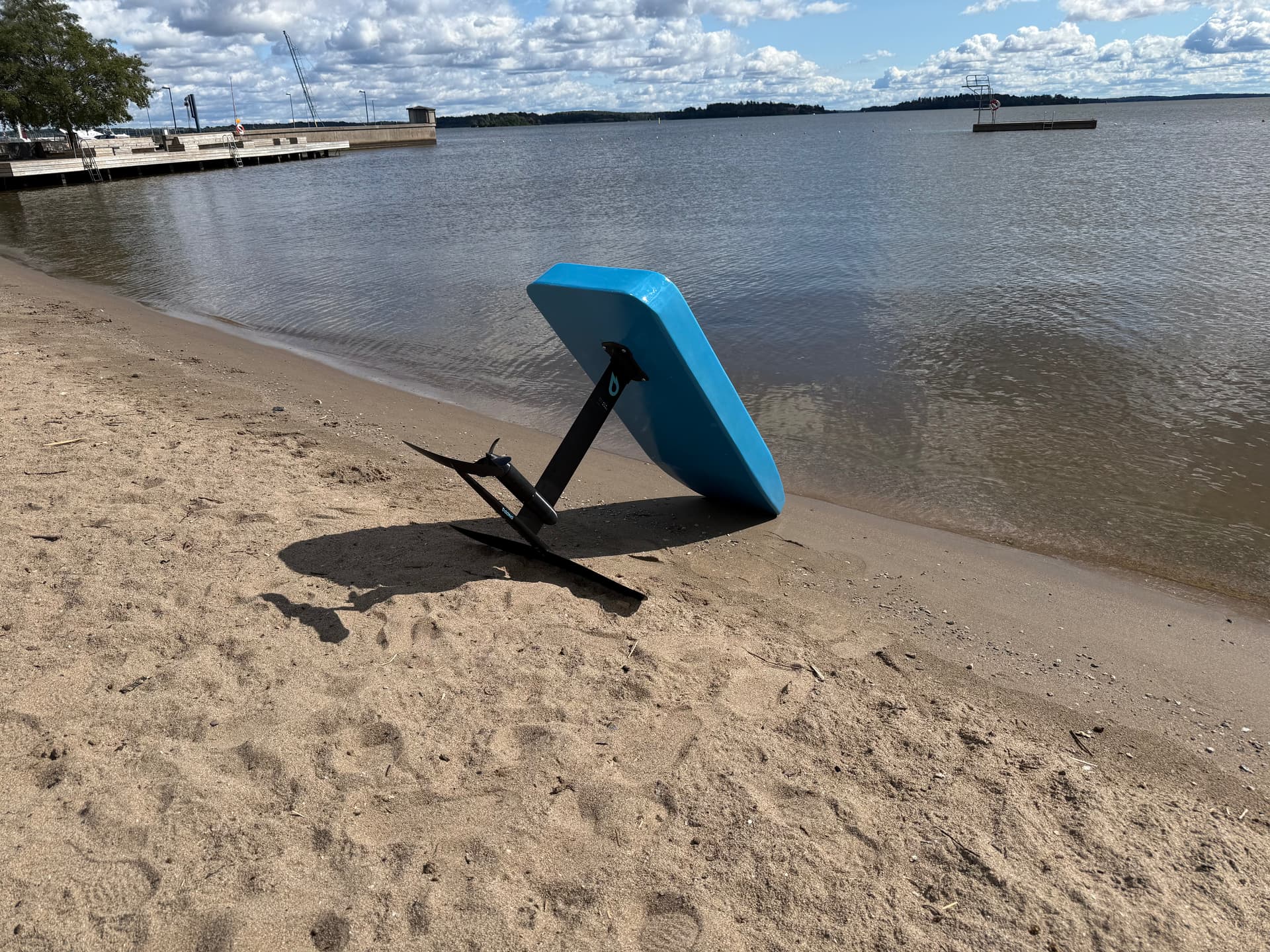
For the past two weeks, me and my friends have been foiling a lot. The eFoil is holding up really well. I made a rubber gasket to seal between the mast and board for easy assembly.
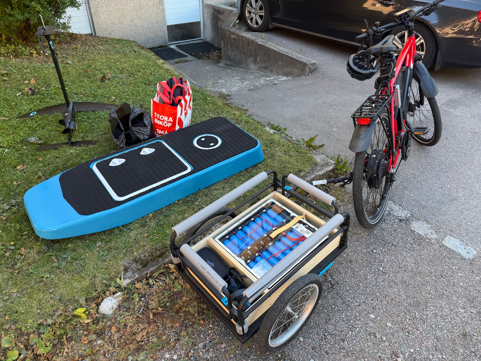
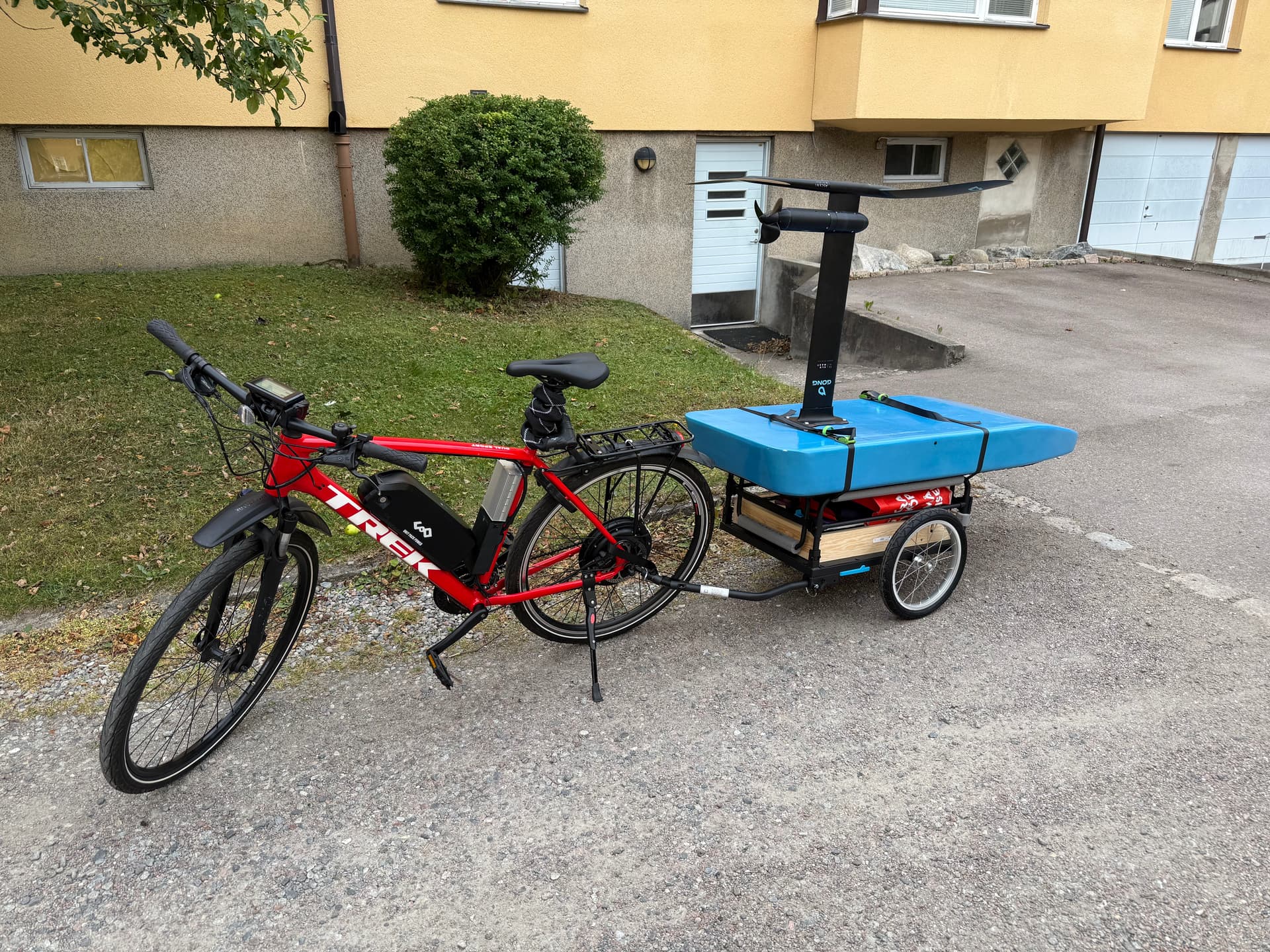
I found it easier to transport the eFoil on a bike trailer than with a car, because I can ride all the way down to the beach, avoiding long walks where I had to carry everything from a parking lot.
A lot of practice was required, but I can now easily stand up and foil for long sessions. It pulls around 1.2kW cruising my 90kg. With the 2kWh battery, I estimate a battery time of 1h 30min of continuous cruising. I have not dared to go faster than 20 knots yet 
Also, I made a build video: https://www.youtube.com/watch?v=JtgKXoviQP4
3 Likes