A-Foil philosophy project (Andrey Filosofov)

Hello dear community!

My name is Andrey Filosofov

I am here to tell everyone about my plans to build efoil and ask questions, which I have accumulated quite a few.

I was inspired by ready-made projects such as LiftFoil and Flite for the construction of the hydrofoil. I was also interested in some hand-made projects with gearboxes, but for now I decided not to use gears.

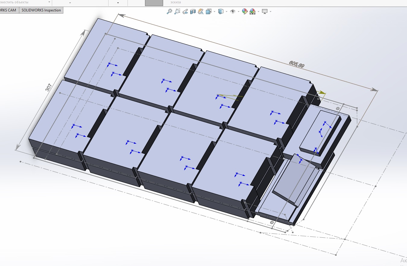
I already have a mast and a plate, I bought them here:

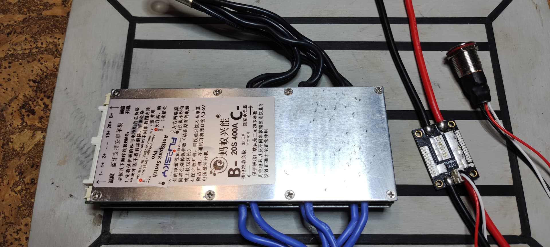
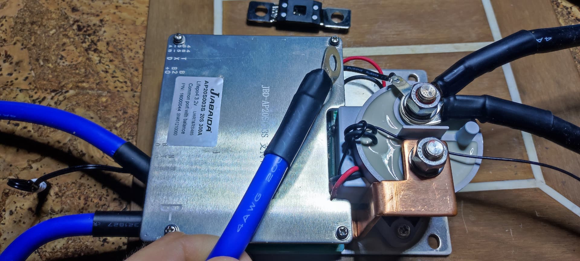
I also seem to have decided on the battery, it will be LiFePo4 with a maximum charge of 60 V. This voltage is used, for example, by Flite.
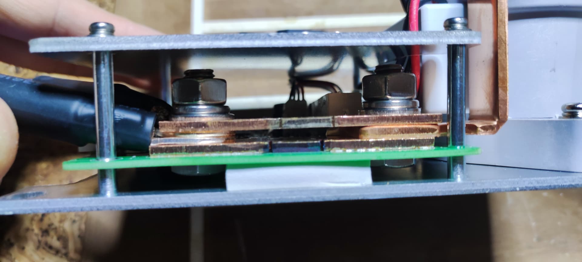
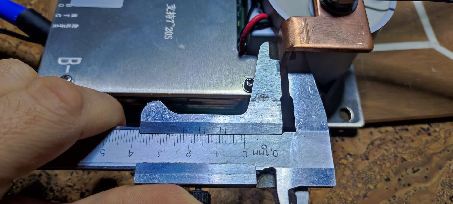
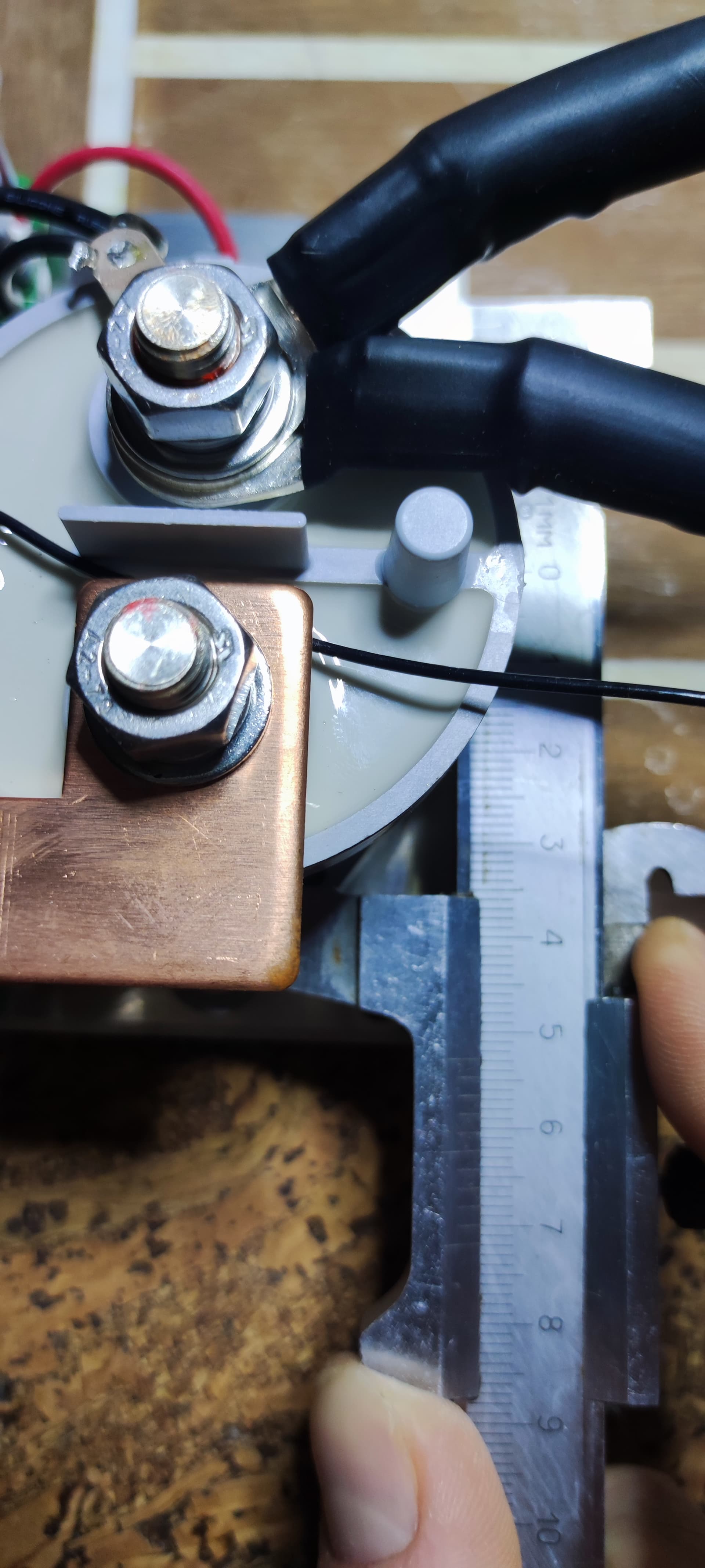
The charge board will have an anti-spark, a button and a display.

Recently, however, I began to doubt the choice of voltage, as I hear a lot of talk about safety. Therefore, my question is: how much does the risk of getting problems with current increase at 60 V, as opposed to 50 V? With an average current that the motor will use 50-150A.

The main questions now are about the motor and ESC.

There was a lot of hope for the engine

https://aliexpress.ru/item/1005001883262671.html?spm=a2g0s.8937460.0.0.398e2e0edCVqMk

But I hear a lot of conflicting reviews.

Still not clear:

  • with which propeller its current consumption will be optimal for 50 V and 60 V

  • is it really well protected from water?

  • Does the CV actually correspond to the declared one?

It has a good price, and I really would like it to work well.

I am also looking at this engine with a standard 190mm / 7.5 ‘’ propeller. However, the following are not clear:

  • is this setup, assuming 60 V, will it be optimal with 100KV or 120KV?

  • how many amperes does this motor consume in the worst case scenario (100 KV and 120 KV)

All this is needed to determine the ESC.
I plan to use the regulator without forced water cooling, it will be located close to the plate. The plate and mast will dissipate heat. I consider this scheme optimally, since only 3 wires are needed for switching, there are no other unnecessary elements.

At first I wanted to use a regular hobby regulator like this

https://aliexpress.ru/item/616319017.html?spm=a2g0s.8937460.0.0.50b62e0eXtydQU

But after reading the forum, I realized that VESC has excellent opportunities.

It remains to decide on the power, the price strongly depends on this.

Please tell me,

Is this ESC ok?

https://aliexpress.ru/item/10000070117683.html?item_id=10000070117683&sku_id=20000000117854131&spm=a2g0s.8937460.0.0.816c2e0e8KhGZc

Or is this enough?

https://aliexpress.ru/item/10000070081915.html?spm=a2g0o.productlist.0.0.58152cc41lDGF2&algo_pvid=b0e8bed4-63a3-42d7-8e49-6a4bb259ea44&algo_expid=b0e8bed4-63a3-42d7-8e49-6a4bb259ea44-36&btsid=0b8b034a16231085885883926e37f9&ws_ab_test=searchweb0_0, searchweb201602_, searchweb201603_

Maybe just use Trampa?

Thanks in advance for any answers.

Can’t recomment mtvesc6.12, see here: Maytech 200A MTVESC6.12 VESC 6 based ESC - #13 by sat_be
I would suggest to use maker-x Hi300 instead: Go-FOC HI200/HI100 4-16s 75V 300A electric Surfboard Electric Motorcycle Electric kart bicycle ESC VESC - MakerX
Or of course Trampa 75/300 or 100/250: VESC VEDDER ELECTRONIC SPEED CONTROLLERS - Presented by TRAMPA
A200S is is also a good choice but the 16S version is unavailable at the moment (12S is available): A200S V4.1 - TeamTriforceUK

3 Likes

Trampa and A200S look just fine, but I will most likely be looking towards the HI300 (75V 300A), it is very good for the price, and it looks good.

Were you aware of any problems with him?

Thanks for the caveat on mtvesc6.12. I almost bought into its presentation and additional functions, such as an antispark

I got one that is HGL-Tech branded for even cheaper but it is sold out: https://firduo.com/products/hgltech-hi200-75v-200a-esc-base-on-vesc-for-e-foil-surfboard-hydrofoil
The other two variants available on this site and also from Flipsky are slightly different, one is the watercooled version and the other one hast 2 uart ports and an aluminum lid. Although they are considered an upgrade some people had problems under load with those due to a production issue. They also cost more. The maker-X is still available and looks identical to the one I use. Mine works fine with only passive cooling in an alu box on an alu plate, 63100 outrunner, max motor current 150A. There is always a risk when buying stuff directly from China, that’s the price for getting it cheap.

1 Like

With two UARTs, is this this one?

https://firduo.com/collections/hgltech-esc/products/hgltech-200-75v-high-current-200a-esc-base-on-vesc-with-aluminum-case-for-e-foil

Are there many advantages of the second UART? Here on the forum I read that one of the creators ran into a problem when he could connect either a Bluetooth modem or a remote control to his ESC.

I plan to start using this receiver with a remote control

Obviously it uses the UART, which obviously carries all the telemetry.

Do I need to connect a PWM cable?

Later, I want to design my remote, which, with an e-ink display with GPS, is based on open source projects.

By the way, here I see a lot of travel tracks that people post. As far as I understand, they get them through the VESC system. In this case, what is the GPS module connected to?

Some people got a unit of a bad batch of this vesc clone which they had to send back. Second uart could help if you want to connect metr.at and a remote that displays telemtry data like voltage, current, battery levele a.s.o. The logs provided with a link are from metr.at, a module you connect to either can or uart port, there are different versions available. Either you use the gps of your mobile phone or you buy a metr module with gps module and sd card. Metr also allows you to configure the vesc through tcp bridge. This way you don’t need to connect it to usb to change parameters.

1 Like

Thank you for your interest.

In fact, I have already seen liquid ink display on some foil remotes, and I spied the idea from them (I don’t remember who has such a remote control).

So far, the project is at the level of an idea, and at the beginning I want to try a ready-made solution, for example, Maytech.

For now, I’m evaluating the feasibility of creating a completely custom console.
But maybe I won’t go into the jungle of programming, but I’ll limit myself to replacing the display with electronic ink on one of the ready-made solutions

Hello friends!
Long time no see!)))

Finally, there was time to do my development.

Here is my future LiFePo4 battery.
Elements have already arrived to me, which at a peak can produce up to 300A.

I want to use this BMS (photo). There is also an additional 5A balancer.

For safety, I looked towards the Antispark switch, and ordered this one: https://aliexpress.ru/item/4000585854437.html?sku_id=10000003431212136&spm=a2g2w.productlist.0.0.24543aa9AfD41O

At par, it has 280A continuous current, but something is hard to believe.
Upset that he only has 12 AWG wires. By the way, 6 almost the same wires depart from my BMS. True, there are areas where you can solder additional ones. I think to connect all this with one thick wire 6 AWG.

What do you think about this antispark? Will it withstand at least 150A?

In general, I expect my battery to deliver up to 250A in peaks, although this is likely to be rare. I want to use it not only for e-foil, but also for my other electrical devices.


In the end, I’ll probably come to this antispark, but I don’t want to, because it is not cheap. The battery turns out to be almost gold.

I don’t think you can thrust those anti spark at this level of amp , I might be wrong but not many Efoil run anti spark , better result with a coil relay

You might want to take a look at this:

https://m.fr.aliexpress.com/item/1005003092762026.html?trace=wwwdetail2mobilesitedetail&spm=a2g0n.store_m_allProduct.allProducts_6000674210337.1005003092762026

I think never tested here but it will probably work better than those anti spark

2 Likes

How would the relay work ? If the BMS get damaged for whatever reason, will it still cut the pack power with the relay ?

1 Like

Thanks, I’ve seen these boards with relays, they should probably perform better than transistors.
Perhaps I will use such a board in my next developments. The principle of operation of this relay is not yet clear, is it contactless?
How long will its resource last?
Another obvious disadvantage of the relay is its size. Perhaps it will not be so cumbersome if you turn the relay itself sideways.
Also, the price is not cheap.

But I would still like to know the reviews about such an anti-spark switch, like mine, on transistors. I will probably start with him, because he is already on the table.

I am also tormented by a fundamental question: do I need to install the BMS display in the battery? At first I wanted to do this, but then I thought that it would not be possible to look at him while riding. And it takes up a lot of space. It is also necessary to design a transparent window in the battery case for it. Recently, drawing my battery in 3D, I come to the conclusion that it is better to make a sealed connector in the case for connecting the display, and at the same time the power button. What do you think?

I am going to make the battery case from an aluminum sheet of 1.5 - 2 mm, make the cover from the end, casting it from aluminum. That is why it is so important to design everything in advance)))

What open source remote control project do you mean?

Да, мне тоже интересен ответ на эти вопросы. Сейчас я задаю их продавцу.
Вот инструкция, но ответа на этот вопрос там тоже нет (я не нашел)

Китайский продавец платы ответил следующее:

“it has the protection function, in most cases it will closed”

I don’t remember which particular project I had in mind then. Some of the projects are discussed here

Ok so the relay is a NO type. « Normally open ». If you lose power there is no more current flowing through the wires, which is nice

I hope it works this way.

By the way, I found where similar relays are sold separately from the board, maybe someone will be useful.

I have on of those from AE, not tested yet though. Its a heavy piece of equipment, seams very high quality compared to ordinary junk from AE. Would not be surprised if its a original part, but only real word testing will tell…

1 Like

Impressed by the new BMS. The design is much more serious than my previous one. Two 4 AWGs are connected to each input and output! As I understand it, this is a large margin. I decided to remove one wire - it will come in handy on the farm.
But then I looked at Wikipedia, the 4 AWG wire passes 95 A at 90 degrees Celsius.

The Chinese write in the documentation that it can up to 200 A (probably referring to the maximum current and a hot state). So I wondered if it was worth leaving only one wire?
This is supported by the fact that it will be more convenient to mount batteries in the case, and the consumption is unlikely to be at such high levels. And if it does, then for a short time, what do you think?


The seller also promised to put a power button in the kit, but instead he put in a 400 A fuse. Hopefully, there is an opportunity to connect the button, I will figure it out.