Any STL files for a Rx Box including BEC, or plans to design one? I’m happy to volunteer to do that but don’t want to double up if it’s already done.
Edit: Connecion Examples are now on GitHub as well
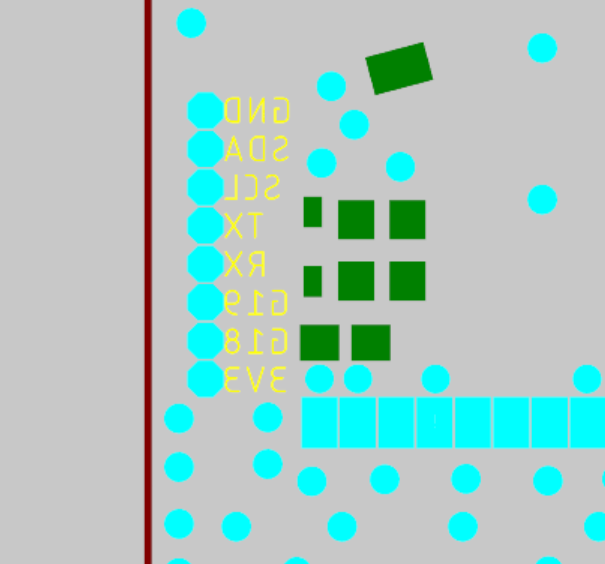
They can be opened individually with the little arrows in the front:
This picture is an example only, please always check the GitHub for the newest diagrams!

Any questions or feedback welcome ![]()
2 Likes
I have not designed a case yet. Happy for your input
meas ubat connect to + is to get the voltage of battery on the remote display ?
Exactly, just to measure. Power supply is through the 5V BEC/VESC of ESC0
I assume canbus does not wort without additional hardware (can → uart converter) right? I currently use the uart of my vesc with an bluetooth module to connect it to the vesc app. But in that case is assume i could just use the UBAT pin for battery voltage right?
Most vesc have 2 UART, so this should still work…Long term the BRRmote Rx can also be used to configure and log VESC data btw
1 Like
When we are on the subject of UART, can you please confirm wich UART can be used for TX GPS?
Thinking about doing TX/RX GPS to try some custom follow code. Should be easy to use a RC car for system validation, then transition that to the boat.
G18 and G19 should be used and mapped to UART1 port. Please also make sure the GPS module can run off 3.3V and does not overload the internal regulator. If you use a 5V GPS, you need a step up that has an enable pin, which must be connected to the power circuitry of the remote itself, so it does not drain the battery.
If you can wait a bit, @macfly1202 is currently developing follow-me functionality for the V2 and I am tinkering with the power supply for that, as most GPS need 5V.
5 Likes
Haha great to know, sent him a message before posting here. We had a session together last summer and it was my first time testing a BREMOTE v1 ![]()
2 Likes
Thanks. For a tow boogie with dual ESC, what would this diagram become to get differential control using UART, using PPM ?
For dual ESC please open the diagram labelled “ESC with BREmote BEC/own BEC” on the GitHub page. It’s all there, for all configurations I could think of.
1 Like
I was hoping to get a non trouble system by avoiding additional circuit boards. I always had trouble with BEC’s in the past, most likely due to condensation.
Instead of a BEC I would rather use a (step-up) voltage regulator to get from li-ion voltage to 5v, if needed.
So for a dual ESC setup I should have stable reference voltage.
So I took a look at the connection examples today.
Where does the RX get reference ground for the “Meas UBAT” from?
Do I need to connect battery ground to one of the BEC GND or will the board get GND from the ESC GND?
I understand. The BREmote BEC has 2 potted regulators on board, so those will be safe. And if the codensation is a problem for the rest of the circuit, it will also be a problem for the Rx itself… so in that case you are better off potting/coating BEC and Rx
It gets the reference from ESC0 / BEC0 GND. Some ESCs connect their battery and signal GND, some don’t. You can measure that with a voltmeter. If it’s not connected by the ESC, run a separate wire from ESC0 GND to Battery GND
Any thoughts on how to implement a 10-30 seconds “start-boost” feature, e.g press throttle then it rises at set curve to given throttle for x number of seconds, then turns off. For usage with prone, dw and parawing starts
2 Likes
Yeah this can be implemented in software.
Just alter the calcFilter() in TX or the calcPWM in RX
With a few while and if clauses this should be doable
I can take a look into that in a few days or you can have a fo yourself
2 Likes
Tnx - Just a few more prototype iterations on maytec remote, then a v2 kit will be ordered ![]() When is the ETA for the nano variant?
When is the ETA for the nano variant?
This would be a great feature for prone foiling. Press a button and then focus on paddling and pop up to get onto the wave. This would be perfect for the smaller nano Bremote where both hands will have more freedom. The one thing I would want would be a way to stop the motor in case you needed to. Just in case you had some drama and fell off and needed the motor to stop.
Ludwig - if you get a chance, this would be a handy feature.
The way I imagine this feature:
Give more than 50% throttle → ramp starts, ramps up, keeps set output for x seconds
At any time if the user lets go of the throttle (less than 50%) the “program” will abort immediately
I will implement this with the nano. Regarding eta, I am on vacation 3 more weeks. Nano will be continued after that, not much to do anymore except beta tests. Few additional weeks until I can release the files I think. Will keep you updated
4 Likes
ht-ct62(esp32-c3+lora) vs nrf24l01(+esp32-c6) vs simply espnow ?
What were your considerations?
ht-ct62 is not cheap… Probably your main priorite is long distance?