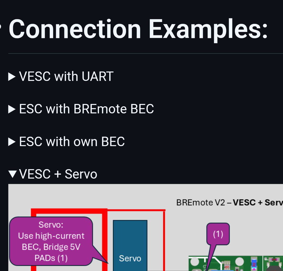
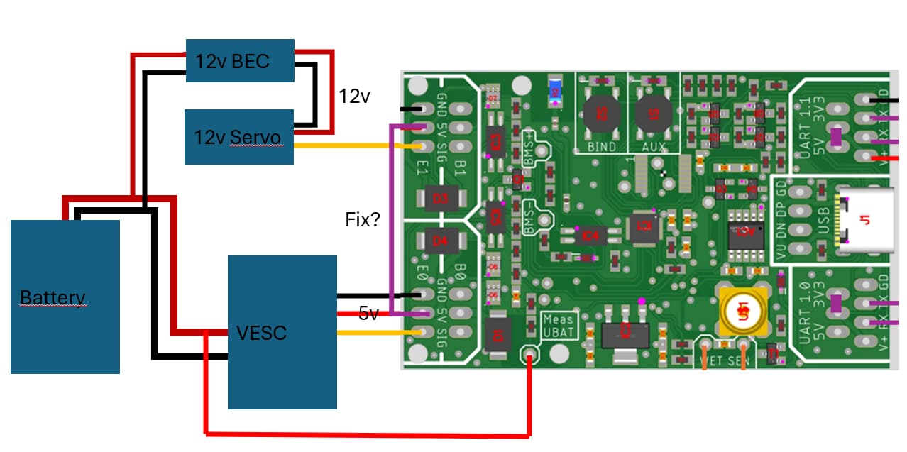
Please connect it like shown in the GitHub example connections
Unfold Your desired example with the small arrow
Please not that the BREmote needs a 5V BEC, not 12V! So in your case you will need a 5V BEC like shown in the image as well as the 12V BEC for your Servo. You can try to cheat and save the 5V BEC by connecting 5V and GND of ESC0 and ESC1 on the PCB. But I don’t recommend that.
Also, can you tell me the exact type of servo? Does it maybe have a 5V output built-in?
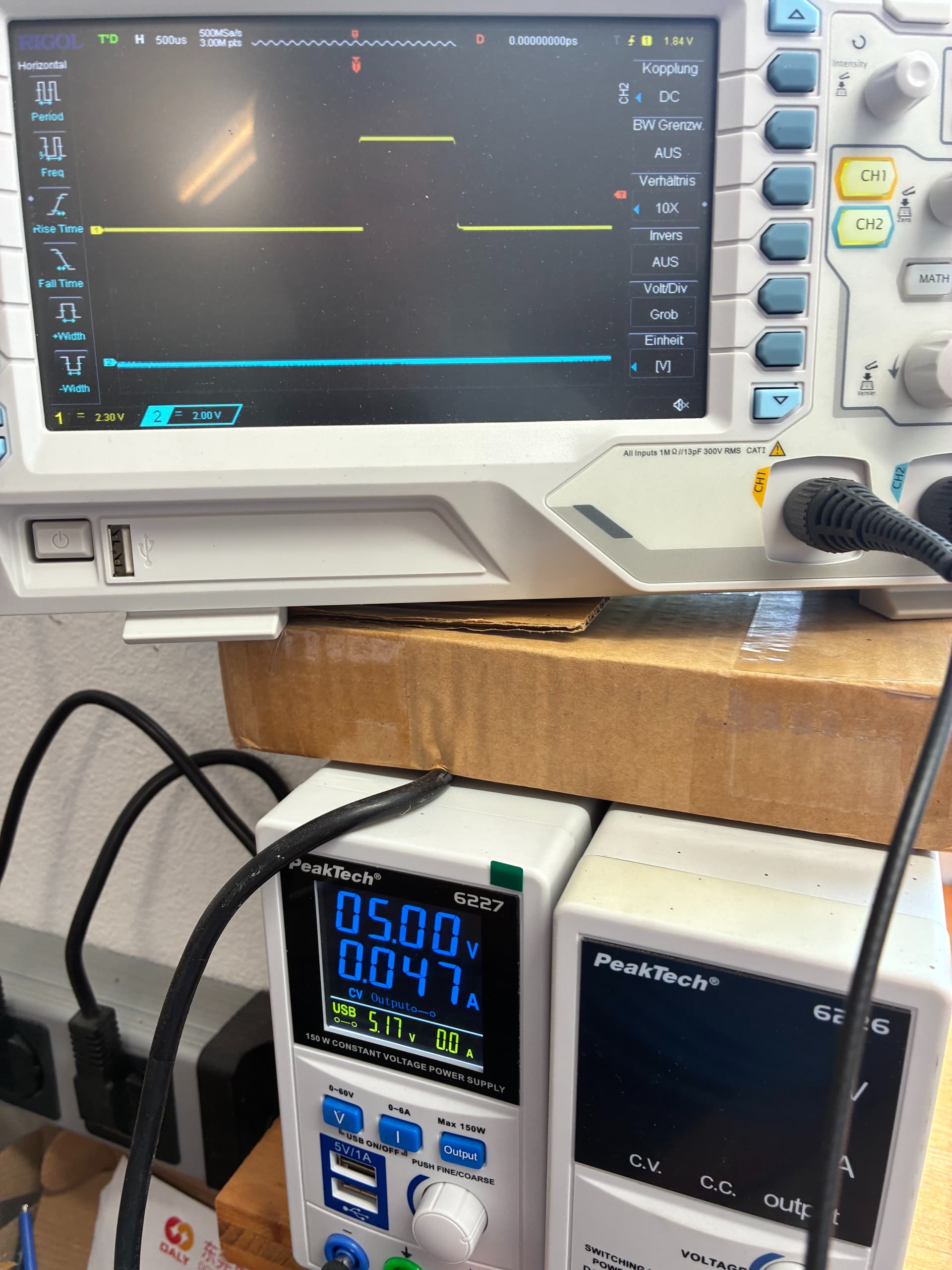
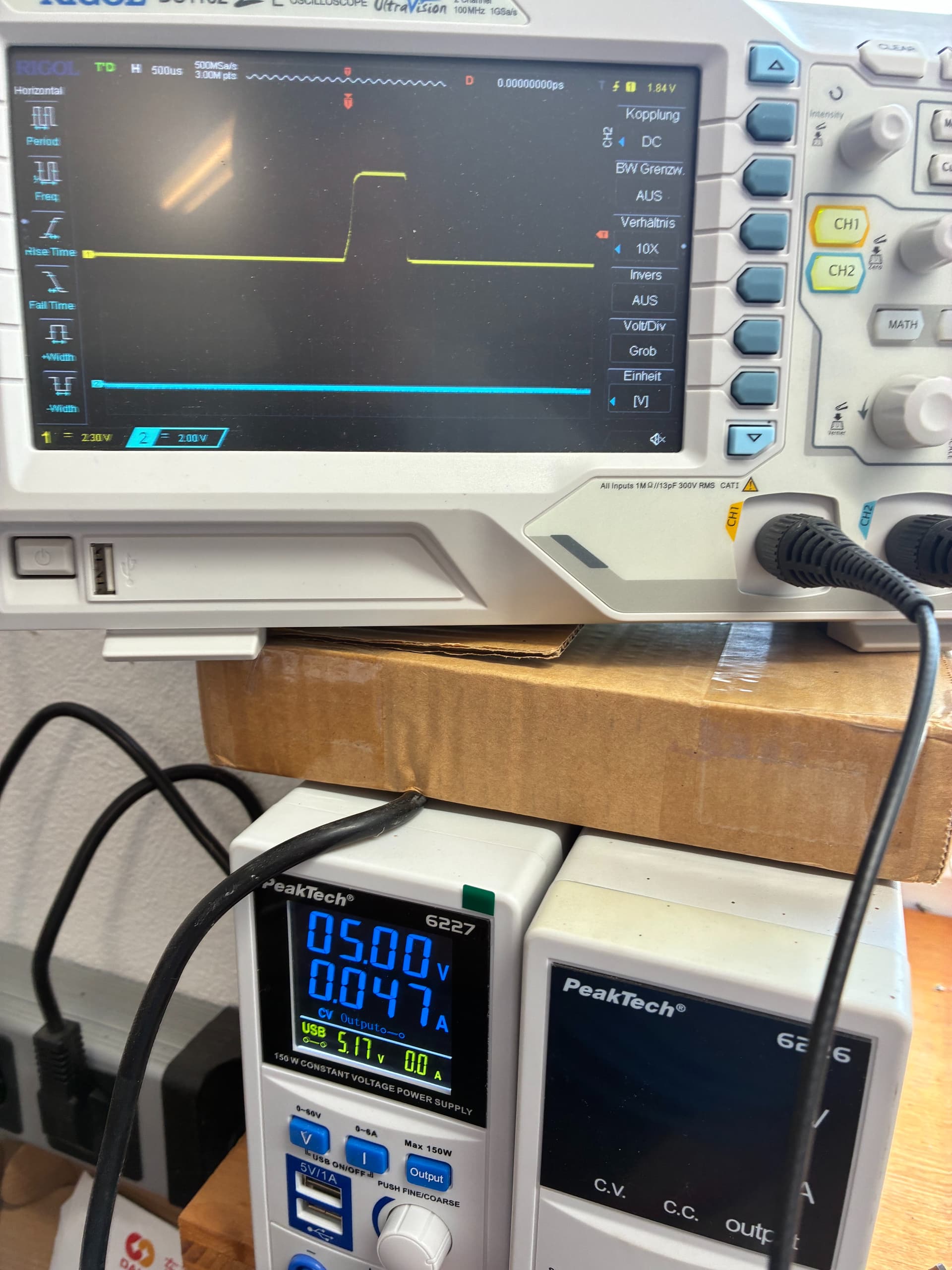
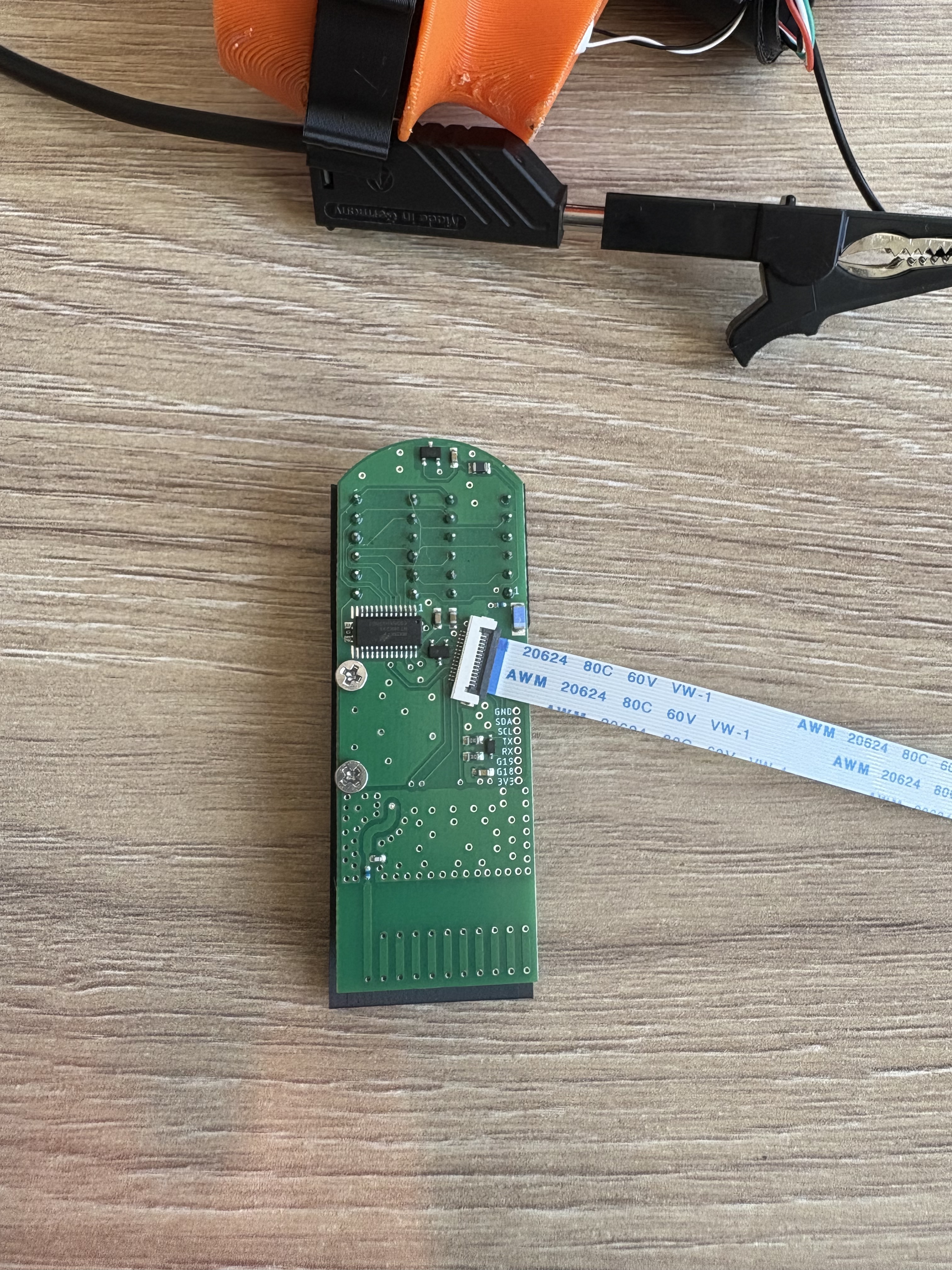
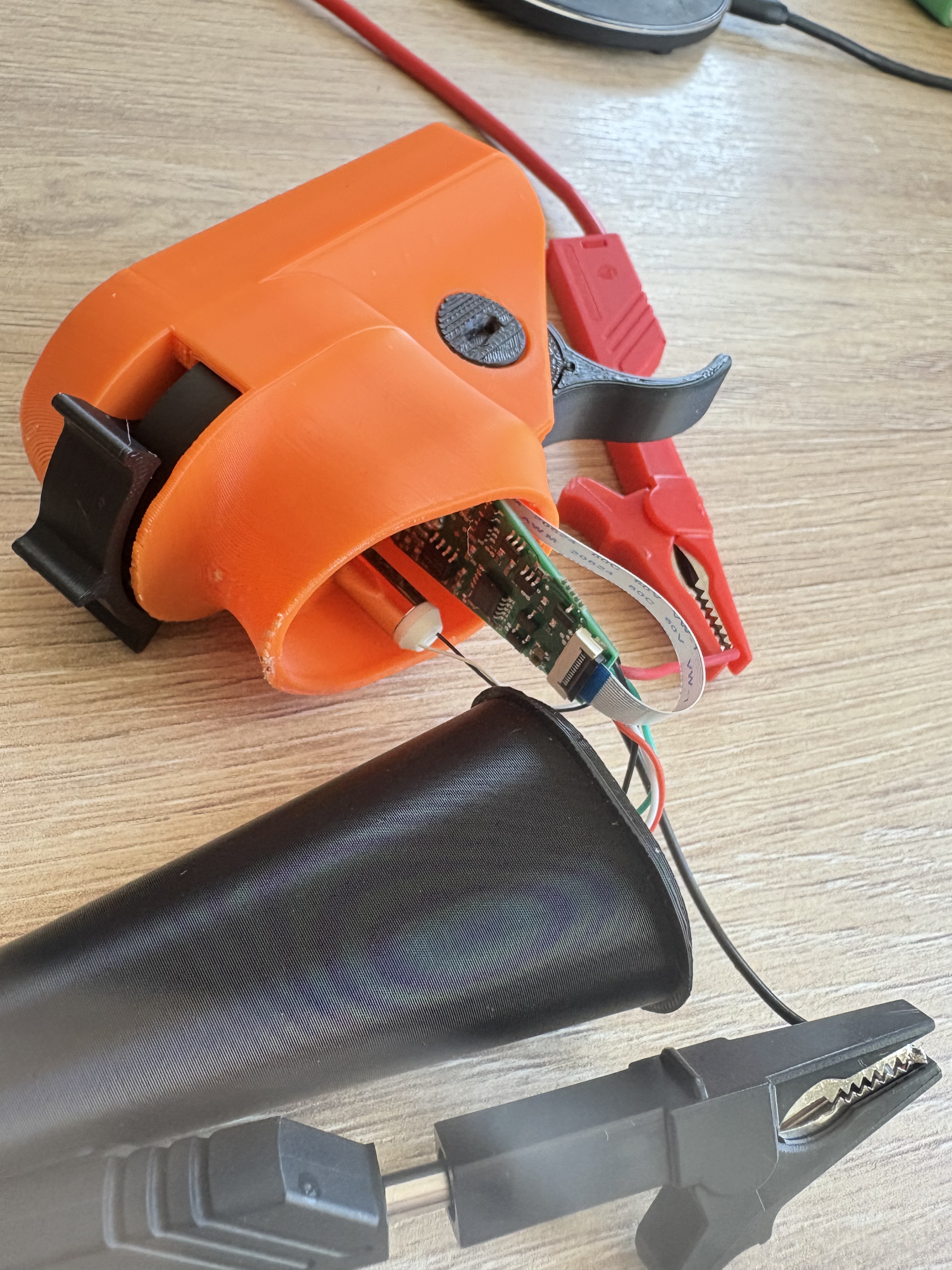
I debugged the RX PWM issue.
I removed everything until I only had the RX powered with a laboratory power supply.
The issue still remains.
After appr. 13 seconds the PWM signal significantly shortens.
Only a power reset of the RX board resets it. A ?reboot does not reset the signal quality.
When I power the RX with USB and enable power supply (on the PWM) after 13 seconds, the signal is already shortened.
It is on both ESC0 and 1.
?printPWM does print stable values, but there is no PWM signal at the time of running printPWM.
I got two RX boards and both have the same behaviour.
The issue is that the SQESC is very picky on the signal length and quality.
It looks to me software caused.
Any idea?
If you want we can have a phone call too. I send you my number in a message.
Thank you Ludwig
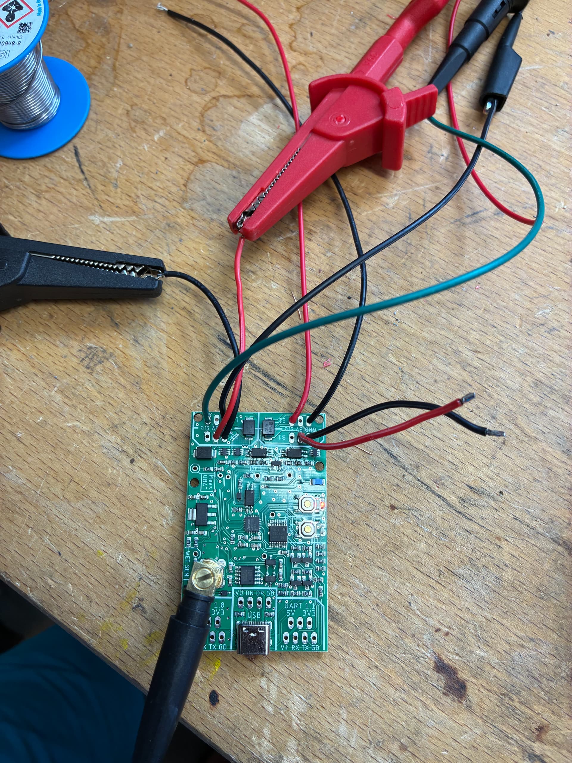
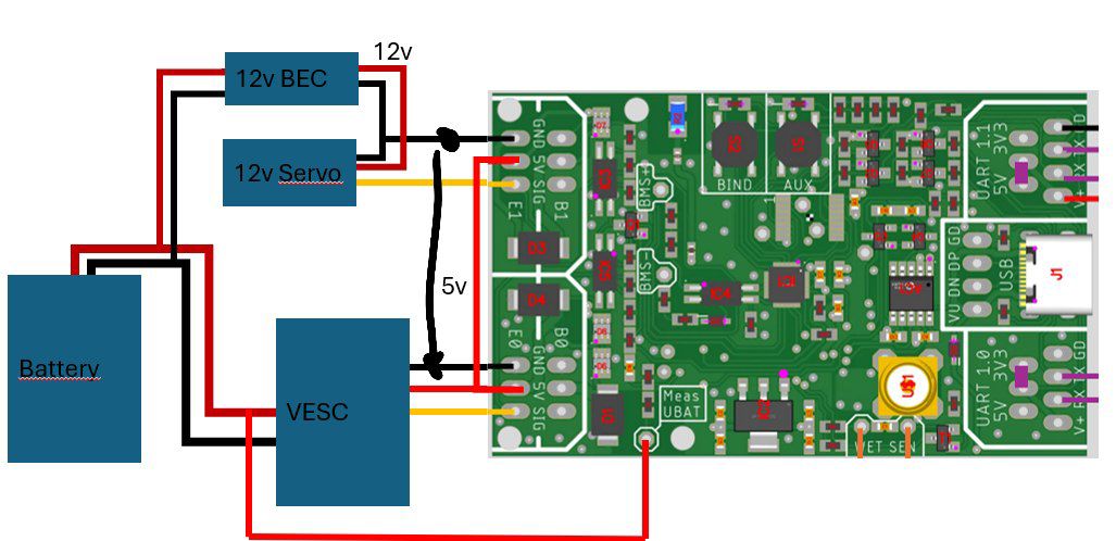
I have the same setup. I removed the 5V line from the servo input, to keep only the GND and signal. Then on the BREMOTE RX, I used 5V from the vesc on the 5V pad of the servo outpout. Without 5V on the RX pad, you get no PPM out.
I’ve not received mine yet. I ordered the day they came out. My order went to status “complete” on the 16th of June but no further updates. I’ve sent an email to openfoil to follow this up a couple of days ago but as yet haven’t had a reply. I’m hoping to hear soon. Was yours to the UK?
Together with the fabulous support of @heiguga we were able to debug an solve the issue. It is in fact in software and I will upload a new version as soon as I am back from vacation. Until then please send me a DM if you have a similar issue.
I won’t receive screws and 18650 battery before 3 weeks.
If I finalize now with old 18650 and bad screws , would it be possible to change the battery later, without damaging the PCB ? I can print all parts again.
You can use different screws on the external parts like trigger and toggle and change them later
Battery can not be changed after you have filled the remote with the potting material.
I think that is too close to the antenna still… You can try but maybe you will have less range or bad GPS reception
Better would be to have the GPS Antenna in the back of the remote, behind the display. You may need to change the housing a bit to make it fit.
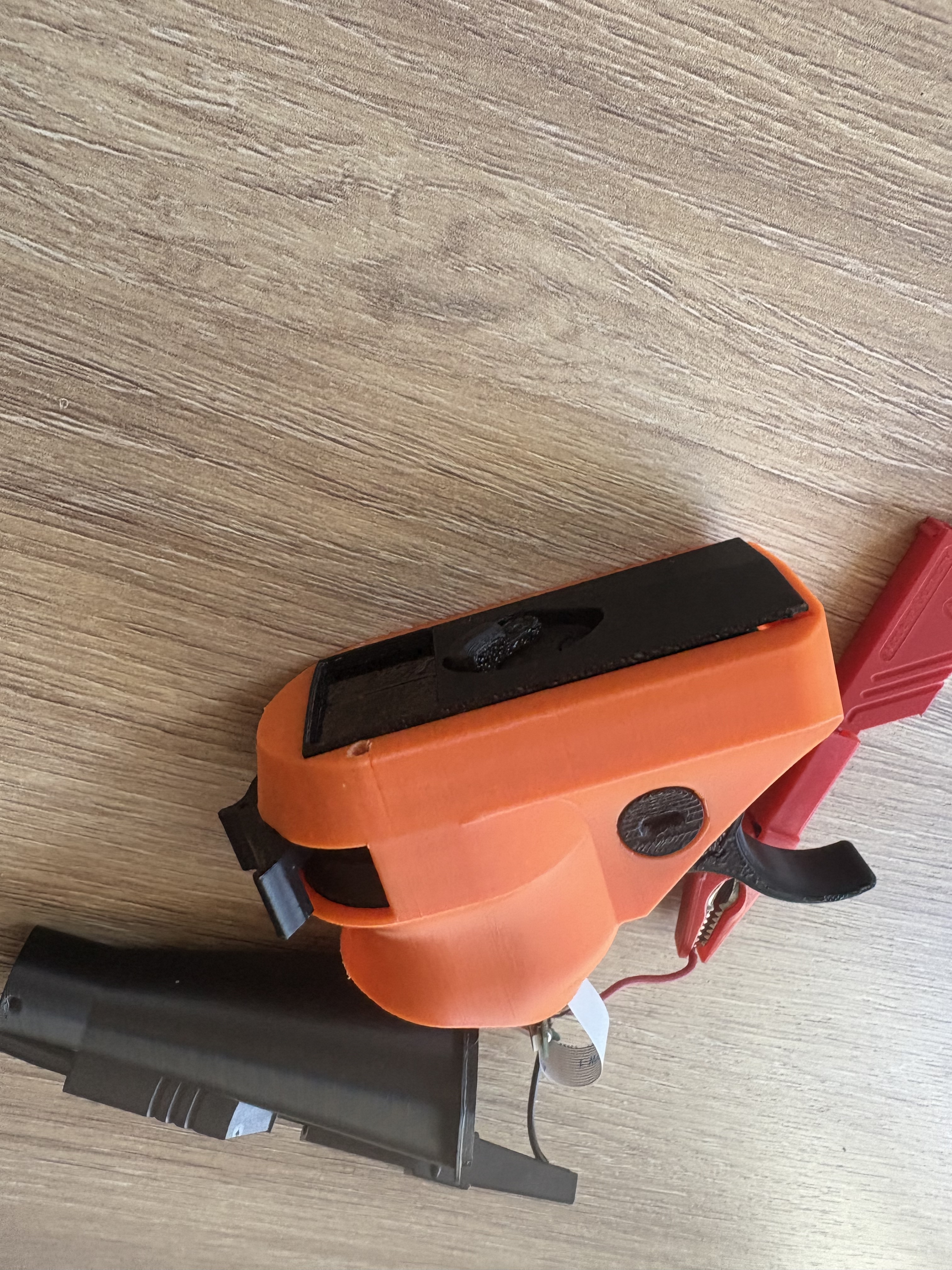
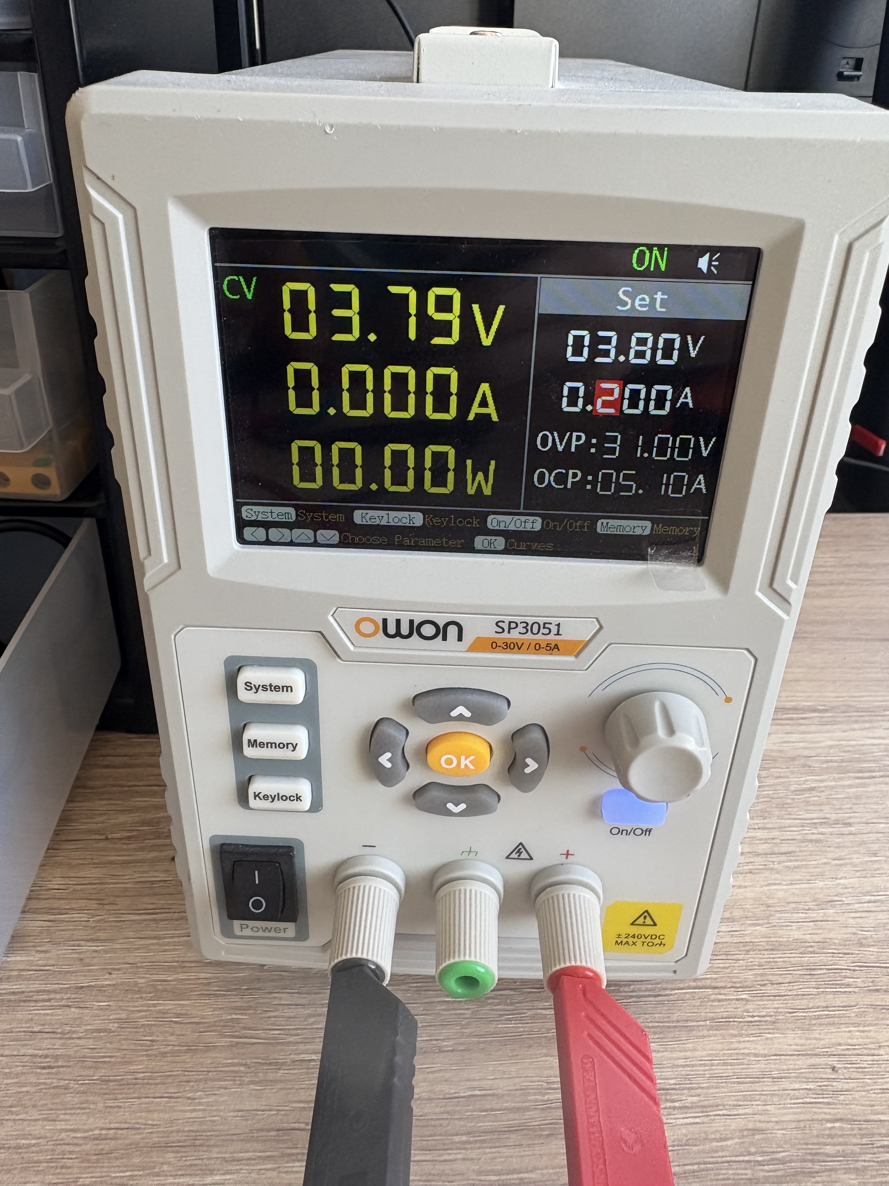
First, thanks for great project and documentation! Unfortunately my kit would not power on. I tried first with the 18650 battery, didn’t work, then connected to my lab power supply, the remote does not draw any current, no matter the switch position. How can I troubleshoot?