Bringing a Dead Takuma Cruiser V1 Back to Life

I bought an old Takuma Cruiser V1 knowing the original remote had been drowned and was dead. That left a fairly obvious question: was it just the remote, or was there more wrong with it?

The board itself was complete. Battery, mast, foil, motor, gearbox and electronics enclosure were all there, and most of it looked too good to throw away. I wasn’t interested in turning it into something it was never designed to be. I just wanted to get the thing working so I could go efoiling.

Getting control of the original ESC

The first useful clue came from posts here on FOIL.zone.

Other people had already worked out that the original Takuma ESC could be driven from a Flipsky VX3 receiver using the PWM connections on the Takuma interface board. Credit where it’s due — that saved me a lot of unnecessary reverse engineering.

The Takuma board even makes life fairly easy because the connections are labelled PWMOUT, PWMVCC and PWMGND.

I wired the VX3 receiver into those connections and got throttle control back.

Unfortunately, pulling the trigger didn’t result in a happily spinning motor.

It stuttered badly.

With the gearbox connected it sounded like something mechanical was destroying itself, but once I removed the gearbox the noise disappeared while the motor still stuttered. The gearbox was really just amplifying the repeated kicks from a motor that wasn’t commutating properly.

The three phase resistances all looked similar on a multimeter and there wasn’t anything obviously open-circuit in the motor.

The original ESC heatsink was warming up as well, so it was definitely switching current.

At that stage the ESC was looking suspicious, but I still didn’t know whether the motor itself had a problem.

A cheap way to answer the question

Rather than keep guessing, I bought a Flipsky Mini FSESC 6.8 60V/100A.

The ESC itself was about US$76, so it was a fairly inexpensive way of finding out what was actually broken.

If the motor still stuttered on the Flipsky, I would keep looking at the motor and wiring.

If it ran properly, the answer was pretty obvious.

I also bought the Flipsky BLE module. Initially that was simply because VESC Tool would let me see what the controller was actually doing rather than diagnosing everything by sound, smell and touching things to see whether they were getting hot.

There was still one unknown before any of this was useful: the original Takuma battery.

The original battery works

The Cruiser V1 battery is a 12S lithium-ion pack, 43.2V nominal, 35Ah and about 1.5kWh, with a 50.4V maximum charge voltage.

There are several small connections between the battery and the original Takuma electronics, so I wasn’t sure whether the BMS expected to see the factory ESC before it would allow normal discharge.

Apparently it doesn’t.

The battery powers the Flipsky normally and remains enabled under load.

That was a fairly important result because it meant I didn’t need to replace a perfectly serviceable battery simply because the original controller had failed.

The motor just worked

I connected the original Takuma motor to the Flipsky and ran motor detection in VESC Tool.

Detection succeeded immediately.

Then I ran the motor.

Smooth.

No stuttering.

I refitted the planetary gearbox and tried again.

Still smooth.

That pretty much answered the original question. The Takuma battery was fine, the motor was fine and the gearbox was fine.

The original ESC was the failed part.

That little US$76 controller had gone from being a diagnostic tool to being the repair.

The size difference is ridiculous

One of the more interesting things about this job is simply putting the old and new electronics next to each other.

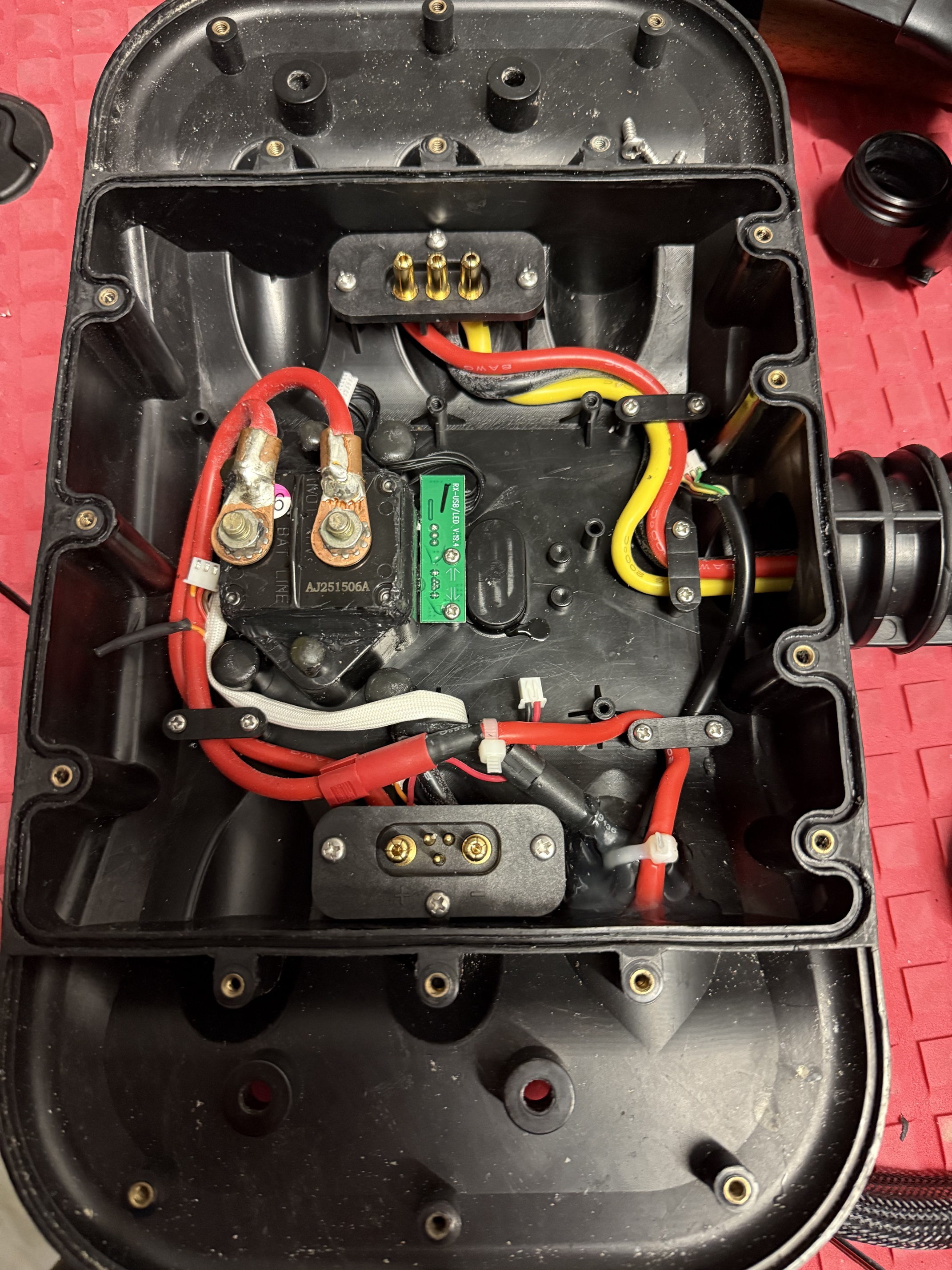
The original Takuma power section is substantial. Large FET board, big capacitor bank, heavy phase wiring and a proper thermal arrangement built into the enclosure.

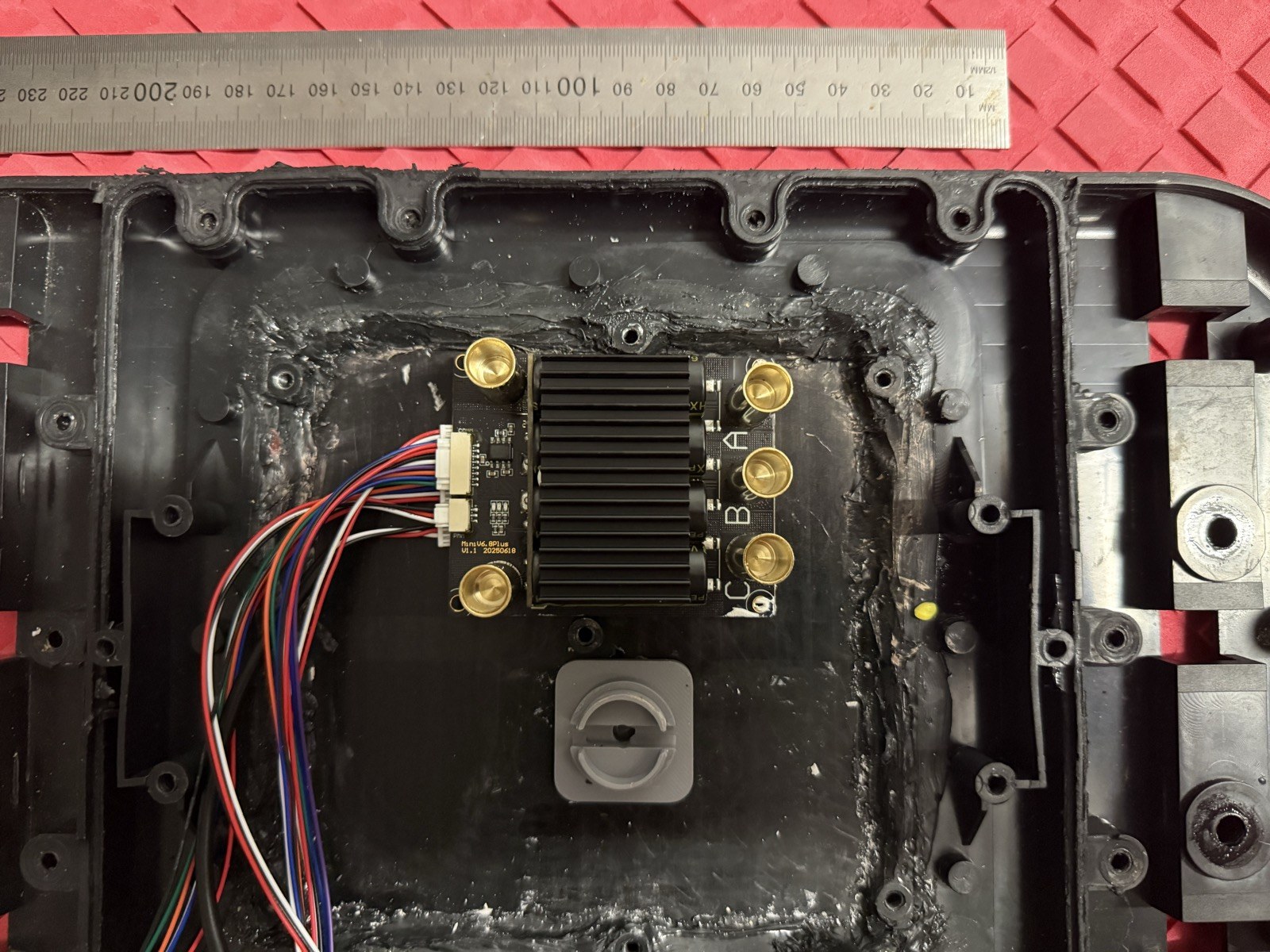
The Flipsky Mini looks tiny sitting in the same space.

That doesn’t mean Takuma did a bad job. It shows how far motor-control electronics have moved on. Modern MOSFETs, gate drivers, PCB integration and VESC firmware put a surprising amount of capability into a very small package.

And unlike the original controller, I now have sensorless FOC, adjustable current limits, live voltage and current information, temperature monitoring, fault reporting and proper logging.

That visibility has probably been one of the biggest improvements.
Keeping the good Takuma engineering

I’ve deliberately kept as much of the original Takuma hardware as possible.

The original waterproof connectors are still being used. So is the contactor, the enclosure and its thermal hardware.

The Takuma electronics enclosure is plastic, but the original ESC used a large copper-looking heat spreader inside it. That plate appears to be electrically floating and was obviously intended to take heat away from the power electronics.

The Flipsky comes with its own small finned aluminium heatsink. I originally considered removing it and coupling the FETs directly to the Takuma heat spreader.

Then I had a closer look.

The Flipsky heatsink appears to be bonded directly to the FETs with thermal adhesive. Trying to remove it seemed like a very good way of turning a working ESC into a broken one.

So I left it alone.

Instead, the Flipsky heatsink is being thermally coupled to the original Takuma heat spreader.

I designed a simple 3D-printed clamp that uses the existing Takuma mounting points to hold the controller firmly against the plate. The first PLA prototype worked surprisingly well. A couple of mounting holes need moving slightly, but mechanically the idea is sound.

The important part is that the clamp bosses sit beside the wiring and clear the components rather than putting pressure directly onto capacitors, connectors or solder joints.

Once the dimensions are final I’ll print it in something more appropriate for long-term use, probably ASA or PETG.

The thermal tests look promising

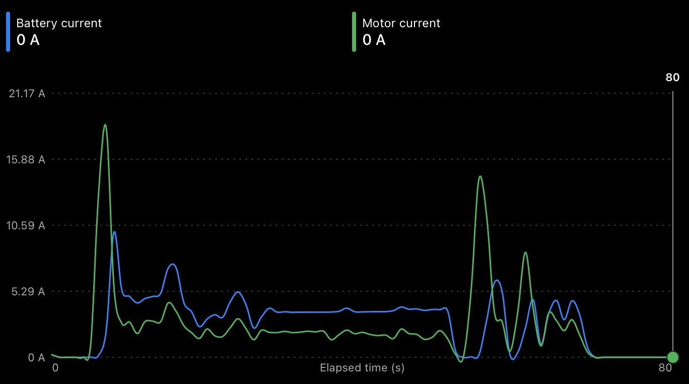
I’ve already run the controller with the new thermal arrangement while logging the ESC through VESC Tool.

In the latest bench test the MOSFET temperature peaked at only about 35°C.

More interestingly, the log also captured the cool-down after the motor stopped. The controller dropped from roughly 35°C to around 31°C in about half a minute.

That at least shows that heat is moving away from the controller rather than simply being trapped in the little Flipsky heatsink.

The proper test will obviously be with the enclosure closed and the foil in the water, but so far there’s nothing suggesting the thermal arrangement is going to be a problem.

VX3 for throttle, Bluetooth for everything else

The VX3 receiver can communicate with a VESC over UART, and I tried that.

The problem is that the BLE module also wants the UART connection.

During development, Bluetooth is much more useful to me.

So the VX3 is connected using PPM and the BLE module gets UART.

The remote still does the important job — throttle.

The phone gives me the interesting stuff: voltage, battery current, motor current, duty cycle, eRPM, temperatures, faults and logging.

That also lets me work on the throttle response properly. I’m currently adjusting the PPM response and throttle curve so there is more usable trigger movement in the higher-power part of the range rather than wasting lots of travel at very low throttle.

That’s tuning rather than troubleshooting, which is a nice place to finally be.

The Bluetooth module may not even be permanent

One of the useful things about VESC is that the configuration can be exported.

Once I’ve finished the wet testing and have a setup I’m happy with for the original Takuma motor, gearbox, battery and the Flipsky Mini, I can save that profile.

That means another Cruiser V1 owner could potentially load a known working configuration into VESC Tool rather than starting from scratch.

At that point Bluetooth becomes optional. You could install the configuration, verify everything behaves properly and then remove the BLE module if you don’t want it permanently fitted…

What actually needed replacing?

Very little.

The board is still a Takuma Cruiser V1.

It still has its original battery, motor, planetary gearbox, mast, foil, connectors, contactor, enclosure and thermal hardware.

The drowned remote was replaced by the VX3 and the failed ESC was replaced by the Flipsky.

That’s it.

The aim was never to reinvent it.

I just wanted to fix it.

Now I’m running out of excuses not to put it in the water.
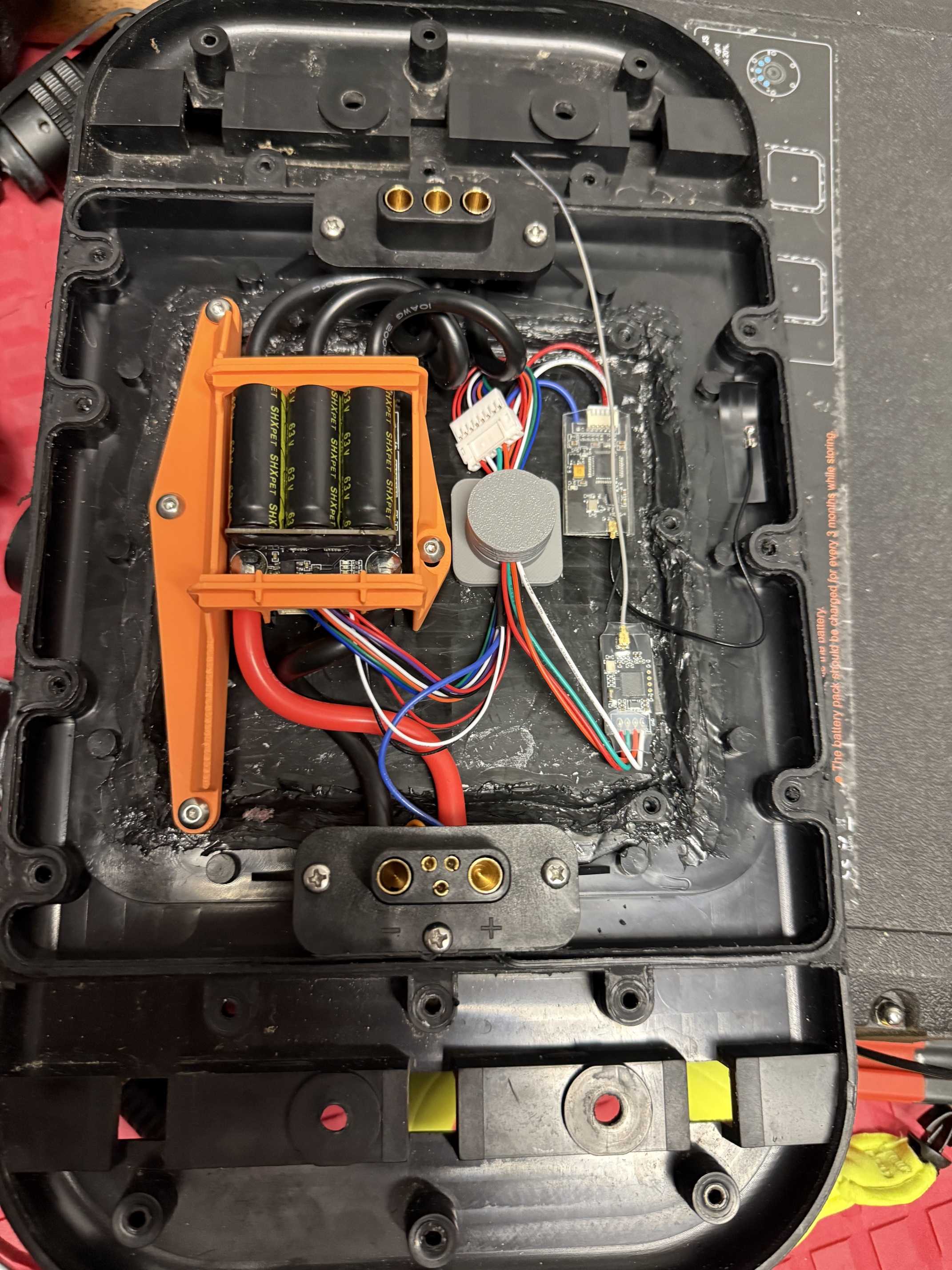

Photo caption: The Flipsky Mini FSESC installed in the original Takuma Cruiser V1 electronics enclosure. The size difference from the original power electronics is dramatic, while the original battery, motor, gearbox, connectors and thermal hardware all remain in service.
2 Likes

Update: first water testing, VESC tuning and the next round of changes

I finally got the Takuma Cruiser V1 back in the water with the original Takuma prop and shroud.

This was the first test where the replacement VESC was seeing a real hydrodynamic load rather than just spinning the drivetrain on the bench, and it answered a lot of questions very quickly.

The good news is that the basic conversion works.

The original Takuma battery, motor and planetary gearbox all run properly from the Flipsky controller, the original prop produces plenty of static thrust, and the board is now genuinely usable again.

The first proper water test also showed where the next improvements need to be.

Current VESC setup

After experimenting with higher current limits, I’ve settled on the following setup for the original drivetrain:

  • FOC sensorless
  • Current, No Reverse
  • 80A maximum motor current
  • 60A maximum battery current
  • 98% maximum duty cycle
  • 100,000 maximum eRPM
  • VX3 remote over PPM
  • Flipsky BLE module over UART

The original Takuma battery is a 12S pack, 43.2V nominal and 50.4V fully charged, so a 60A battery-current limit gives roughly 3kW of available electrical input.

That lines up reasonably well with the commonly quoted 3kW rating of the original Takuma motor.

The 80A motor-current limit is separate from the battery-current limit. It allows the VESC to provide plenty of phase current and torque at lower motor speed without requiring the battery to continuously supply 80A.

Why I stayed with current control

I experimented with the idea of using PID speed control, but I’ve gone back to Current, No Reverse.

That makes more sense for an efoil.

The throttle effectively requests torque rather than RPM.

While the board is still pushing through the water, the propeller is heavily loaded and the motor needs substantial torque.

Once the board gets onto the foil, drag should fall dramatically, the propeller should unload and motor RPM should naturally increase.

I don’t really want the controller trying to hold a particular prop RPM.

I want it to provide the requested torque and let the motor spin as fast as the available voltage and hydrodynamic load allow.

Finding an artificial top-speed limit

During the bench testing I kept seeing the motor stop accelerating at around 65,000 eRPM.

Every time it happened, the VESC was sitting almost exactly at 95% duty cycle.

The configured maximum duty was also 95%.

I increased that to 98% and repeated the test.

The motor then reached approximately 66,500 eRPM.

So the previous top end wasn’t caused by the configured eRPM limit. That is set at 100,000 eRPM and isn’t currently relevant.

The 95% duty setting really was acting as an artificial voltage/RPM ceiling.

I’m leaving maximum duty at 98% rather than going all the way to 100%. That recovers most of the available top end while still leaving a little PWM/control margin.

Working out the actual prop RPM

One thing that had been annoying me was that VESC Tool reports electrical RPM, not actual propeller RPM.

So I did a bit more work to establish the relationship.

The Takuma uses a 4:1 planetary gearbox.

I also recorded the output shaft with a single tape marker at 240fps while logging VESC eRPM.

At around 8,800–9,000 eRPM, the measured shaft speed was around 700rpm.

That fits very closely with the motor being 6-pole, or 3 pole pairs.

That gives:

Motor RPM = eRPM / 3

and after the 4:1 gearbox:

Prop RPM = eRPM / 12

That makes the VESC logs much easier to understand.

Some useful examples are:

  • 42,000 eRPM = ~3,500 prop RPM
  • 50,000 eRPM = ~4,167 prop RPM
  • 58,354 eRPM = ~4,863 prop RPM
  • 60,000 eRPM = 5,000 prop RPM
  • 66,542 eRPM = ~5,545 prop RPM

So we now have a fairly good picture of the real operating range of the original Takuma propeller rather than just looking at abstract eRPM numbers.

First real water test

The first water test was done with the original Takuma prop and shroud.

Conditions weren’t ideal. There was quite a bit of chop and I could really only get useful acceleration running downwind.

The complete session recorded approximately:

  • 78.5A peak battery current
  • 96.3A peak motor current
  • 81.2°C peak MOSFET temperature
  • 58,354 eRPM maximum under water load
  • 10.8km/h peak GPS speed

The motor therefore reached about:

58,354 / 12 = ~4,863 prop RPM

under the heaviest useful water test.

One of the cleaner moving runs was roughly:

  • 76A motor current
  • 52A battery current
  • ~50,000 eRPM
  • ~4,170 prop RPM
  • 10.8km/h peak GPS speed

The important thing is that the motor was nowhere near its unloaded ~5,500rpm prop speed.

The propeller was genuinely loaded.

Static thrust isn’t the problem

I also did several tests standing in front of the board and holding it stationary while applying throttle.

These show up very clearly in the logs because there is high motor current and high RPM but essentially zero GPS speed.

At full throttle I couldn’t actually hold the board stationary.

It pushed me backwards through the sand.

So the system has plenty of static thrust.

The problem seems to be that the board spends too long in the high-drag transition phase without quite getting enough forward speed to break free and foil.

That is also the worst possible condition for the ESC.

The motor is heavily loaded, phase current is high, battery power is high and the board hasn’t yet reached the point where hydrodynamic drag falls away.

The thermal problem showed up immediately

The bench testing made the cooling look almost trivial.

The water testing didn’t.

During longer high-power runs, MOSFET temperature climbed into the low 80s Celsius.

At one point I was experimenting with motor-current limits around 120A, and the controller heated very quickly and produced over-current cut-outs.

Dropping back to 80A motor / 60A battery made the system much happier and gave me some decent sustained runs.

That showed me two things.

First, I don’t need enormous current limits to make the original Takuma drivetrain work.

Second, the 100A Mini VESC was being pushed closer to its thermal limits than I really wanted for a sealed marine installation.

Moving to the 150A Flipsky Mini

For the final installation I’ve decided to upgrade the controller to the:

Flipsky Mini V6.8 PLUS 60V 150A, VESC-based

This isn’t because I suddenly want to put 150A through the Takuma motor.

The operating limits will still initially stay around:

  • 100A motor current
  • 80A battery current
  • 95% maximum duty
  • Current, No Reverse

The reason for the larger controller is headroom.

I want the controller operating comfortably within its electrical and thermal capability rather than sitting near its limits every time the board spends 30 or 40 seconds trying to get onto foil.

The original 100A Mini was excellent for proving the whole conversion.

It showed that the Takuma battery, motor and gearbox were all healthy and that the original drivetrain could be run properly from a modern VESC.

The 150A Mini PLUS is intended to be the more permanent installation.

Using the original Takuma heatsink properly

I’m also changing the thermal installation.

The original Takuma enclosure already has a substantial heat-spreader plate that was designed to cool the factory ESC.

With the first Flipsky Mini I kept its own finned aluminium heatsink intact and thermally coupled that to the Takuma plate.

That worked, but the first water test showed that the thermal resistance between the VESC and the Takuma heat spreader was still too high for sustained high-current operation.

With the 150A Mini PLUS I’m going to do it properly.

The plan is to remove the Flipsky aluminium case/heatsink assembly and mount the controller so that the MOSFET thermal surface is coupled directly to the original Takuma heat spreader.

The intended thermal path becomes:

MOSFETs → electrically appropriate thermal interface → Takuma heat spreader

That removes an entire intermediate heatsink/interface from the thermal path.

Before doing that I’ll obviously verify exactly what is electrically exposed on the MOSFET thermal side and use an electrically insulating thermal interface if required.

But mechanically and thermally, using the large Takuma plate directly should be a much better solution than putting a small finned heatsink inside a sealed enclosure.

Next test: more propeller blade area

Before changing the ESC and cooling arrangement, I’m doing one more useful A/B test.

I’ve printed a propeller with substantially more blade area.

The VESC settings will stay the same:

  • 80A motor
  • 60A battery
  • 98% duty
  • Current, No Reverse

That means the propeller is the main variable.

The idea is not necessarily to chase a higher maximum prop RPM.

What I really want is more useful thrust at lower board speed.

At the moment the board is spending too long wallowing at high power without quite reaching the point where the foil starts carrying the load.

If the larger-area prop can accelerate the board harder at lower speed, it may get through that transition sooner.

Once the foil starts flying, drag should fall significantly.

At that point the propeller should unload, motor RPM should rise and the amount of time the ESC spends at 70–80A phase current should drop.

So the next test isn’t really about maximum speed.

I’ll be comparing:

  • acceleration
  • GPS speed
  • motor current
  • battery current
  • eRPM
  • calculated prop RPM
  • duty cycle
  • MOSFET temperature
  • time spent at high current

If the larger prop gives me a short, hard acceleration followed by lower current and higher RPM once the board is moving, that will be a much better result than simply seeing a bigger unloaded RPM number.

The Cruiser is definitely alive again.

At this point I’m no longer trying to diagnose a dead efoil.

I’m tuning the original drivetrain so it gets onto the foil cleanly and making sure the electronics can comfortably survive doing it.