The information is all here. Let me find you some links…
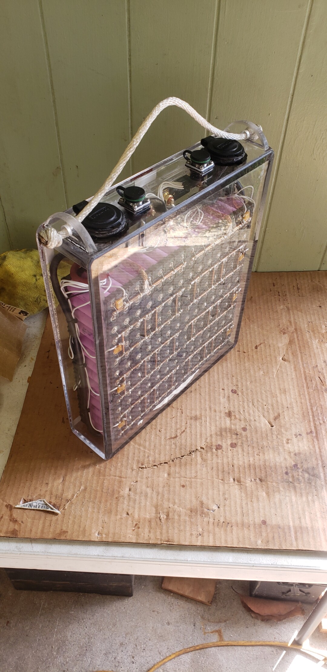
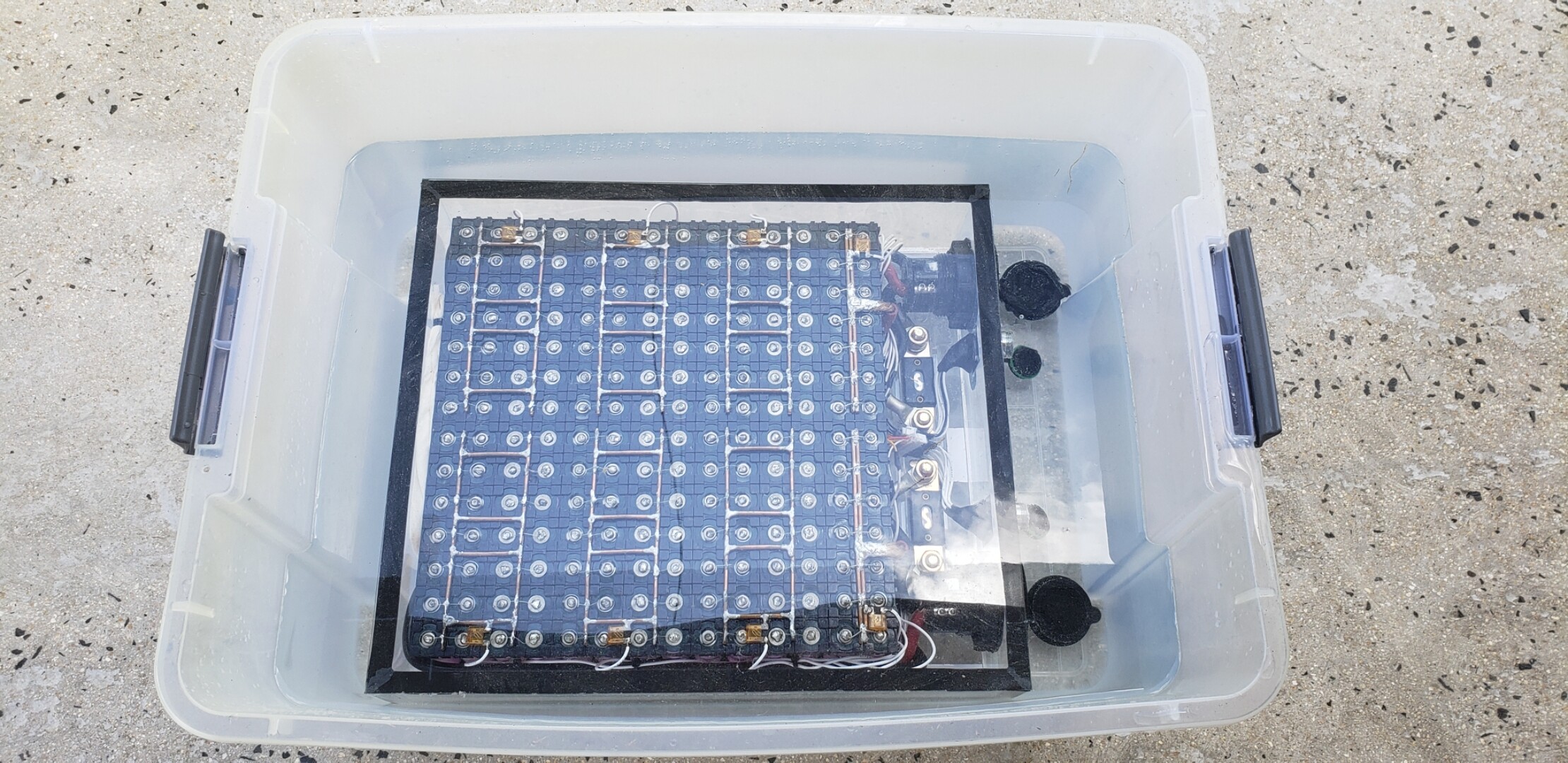
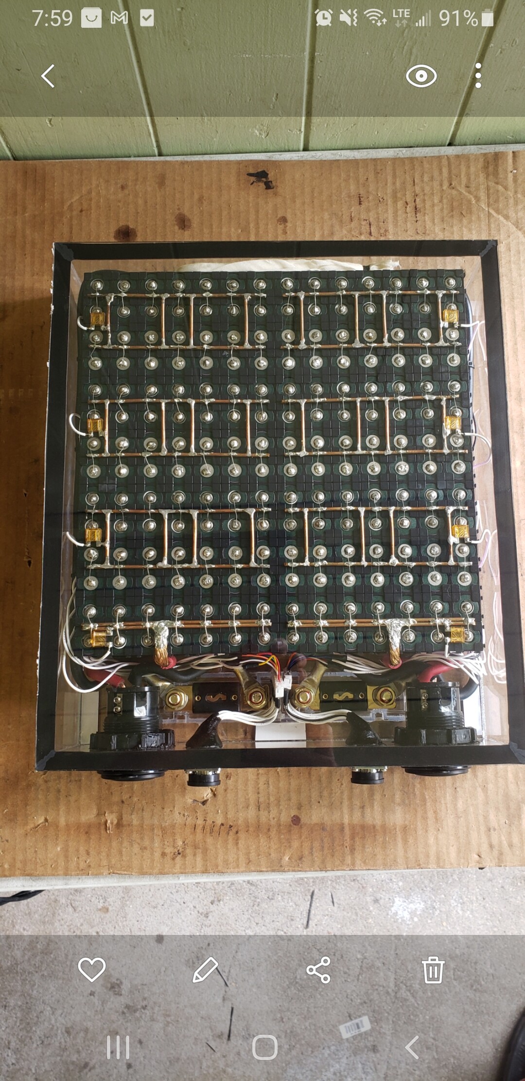
Bus bars are made from 10awg solid strand copper available without insulation at the big box hardware stores. The reason for the 4 cross bar configuration is to keep voltage drop under 3% at 200 amp load.
I have detailed all of these things in this thread. As shown in the link provided in my last post (see quote attached below), the fuse wire does not exceed the temperature of the battery cell at a continuous discharge rate of 10 amps. As shown with thermal imaging.
I am now running two of these batteries with my VESC limit set to 200 amps and with several months of heavy use I haven’t had any issues.
Sean also runs this exact battery build. And so does Eric. So, that’s 4 batteries so far. And I’m gearing up to help some more friends build them.
Excellent design and performance. Maybe one of the few batteries that can provide 200 amps continuous? All 6AWG wire. Very low (none) voltage drop.
There is an enormous amount of information on this forum. Under your profile you will see your summary of read time. There is no short cut to reading. Once you have several days of read time things will start to make sense.
There is no one way to build an e-foil. Everything is a compromise. Get about 5 days of reading and you’ll figure out what you want before you start buying stuff and building. This will save yourself from a lot of waisted time and money!
We’re all here to help. Good luck with your build.
Why do we not put cells in series first and then in parallell? Then we could have balance-monitoring/charging on each individual cell, but i guess there is no chargers with that many balance-leads
Like this:
= is one cell
“+ Plus ’ ’ ’ ’ minus -”
|==============|
|==============|
|==============|
For my 14s14p battery you would need 196 balance leads if you tried to do that.
You drew a 14s3p battery. That would need 42 balance leads. Most balance chargers do up to 8s. So, you would need to combine the 3 groups of parallel cells, and split the series cells into two packs and have two 7s3p batteries.
yes i understand that would be a problem, but if we had a charger that could handle 196 balance leads, would it be worth the extra job of connecting them this way just to get the benefit of full controll over each cell? or is it not a benefit?
you say you have 1,5 h ride-time, i think i need to compromise on ride time to keep down the cost but i still want to go with 3000mAh cells but then i might want highter discharge rate than 15C?
if i build a 12s10p = 120 cells with 20C/cell then i still have 200A total discharge but only 30 Ah opposed to your 42Ah. (30Ahx50,4V=1500Wh) opposed to yours (42Ahx58,8V=2470Wh)
that is 39% less capacity, am i right in this calculation?
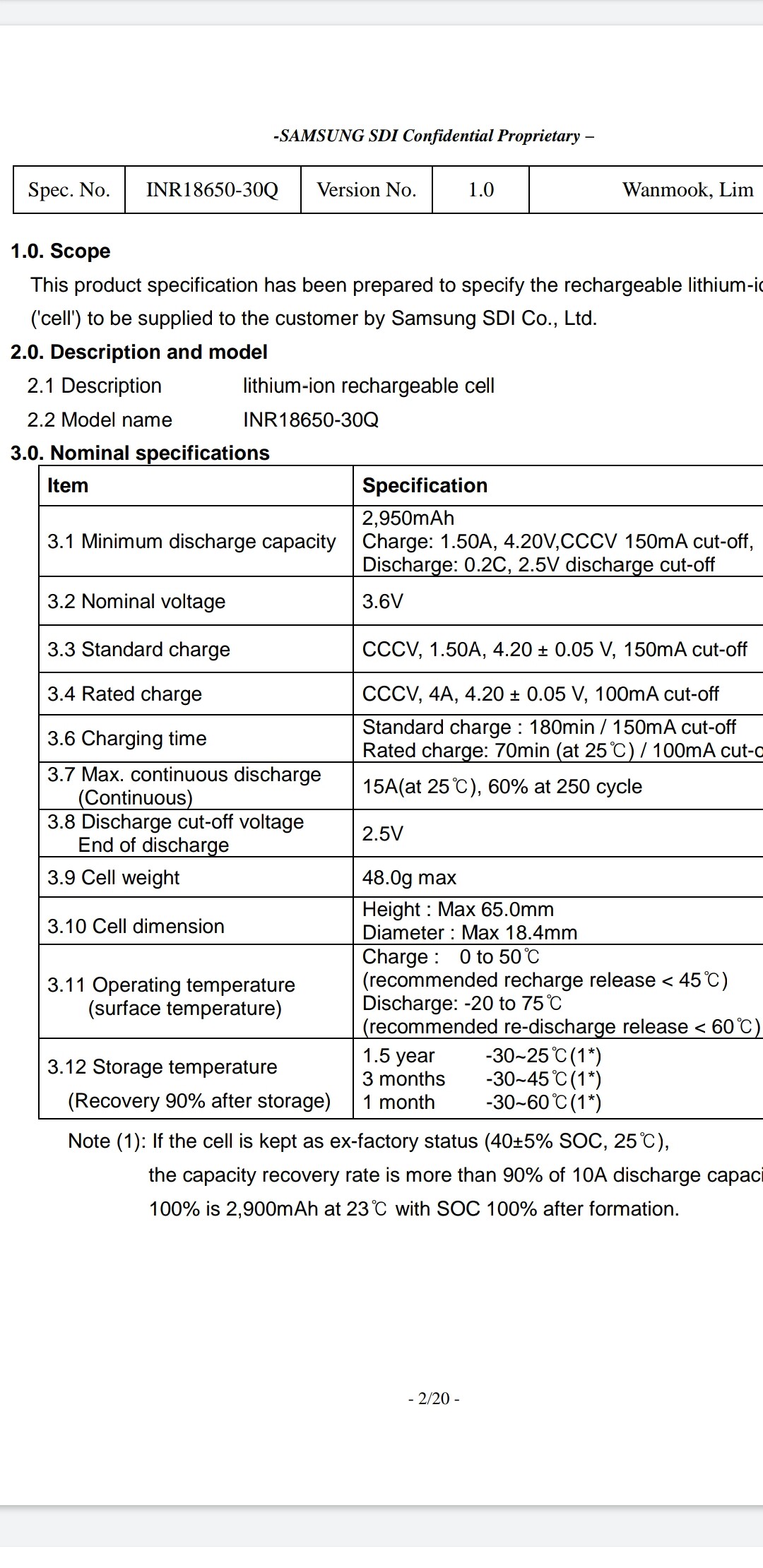
Samsung 30Q cells are among the best you can buy. But, even these have their limits.
You can see my YouTube videos I did on testing these cells.
The cells do not get too hot at a continuous 10A discharge rate. They gets really hot at 15A. And they are so hot the will burn your hand, and start to “melt plastic” at a 20A discharge rate. They are not really a 20A cell. See manufacturer specifications.
They are still within the manufacturer max temperature limits at 15A discharge (75°C = 167°F) , but just so you understand that these cells get very very hot at that rate.
I would build your pack so with your conservative power consumption under continuous use results in no more the 10A per cell draw.
The heat can be a problem in a sealed batter box, and the cells won’t last as long.
It would be better to do 12s14p in my opinion. But, your use might differ from mine. I routinely ride long distances and I use my efoil board to tow other foilers into waves. So, I need the extra margins.
Hi Flightjunkie, so I am building a battery pack based on a combination of inputs from this forum. I really like the idea of individual fused cells, for aditional safety. So I went ahead and also tried to burn through the 26AWG wire with a single cell (spare one). Although the current was much higher than the “recommended max 10A discharge”, the cell did not get warm and is still tested to be normal.
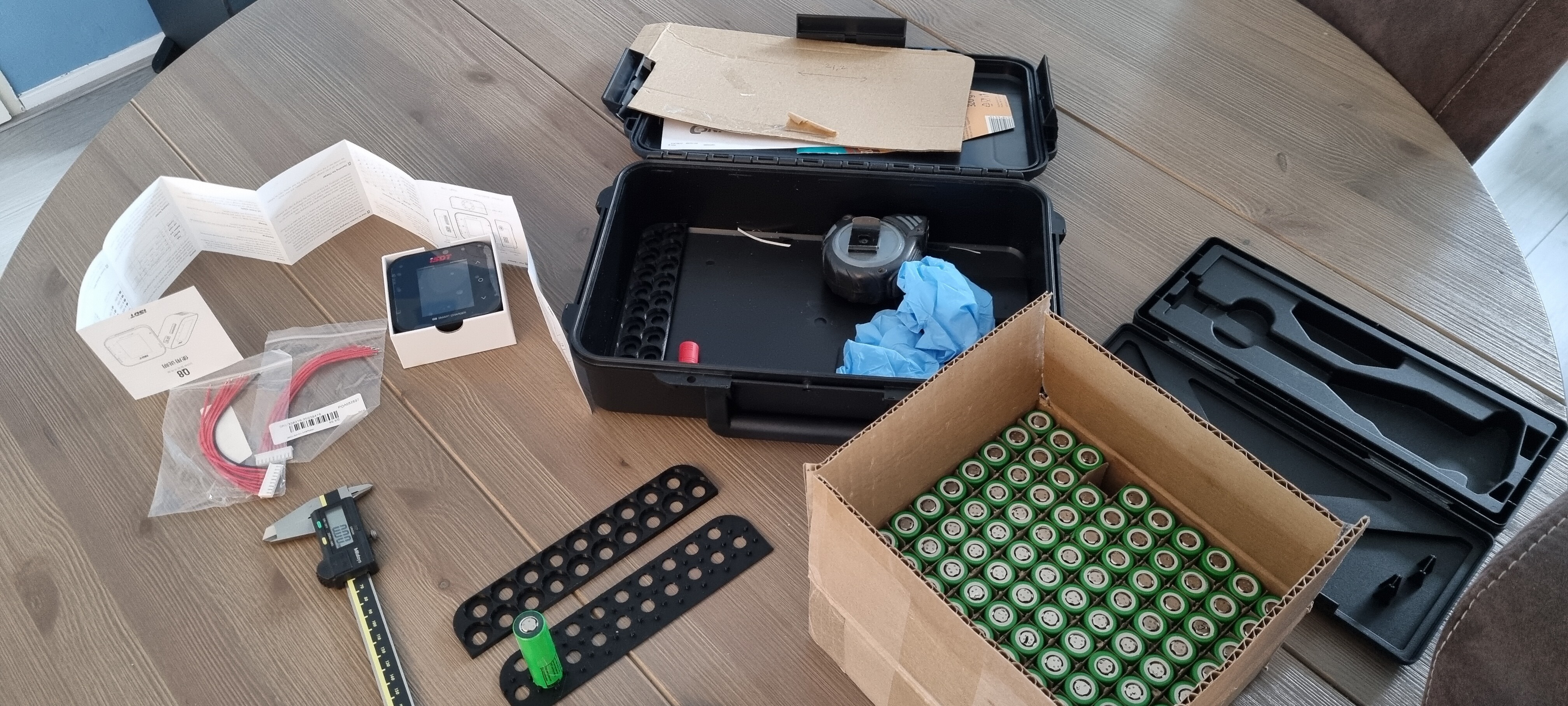
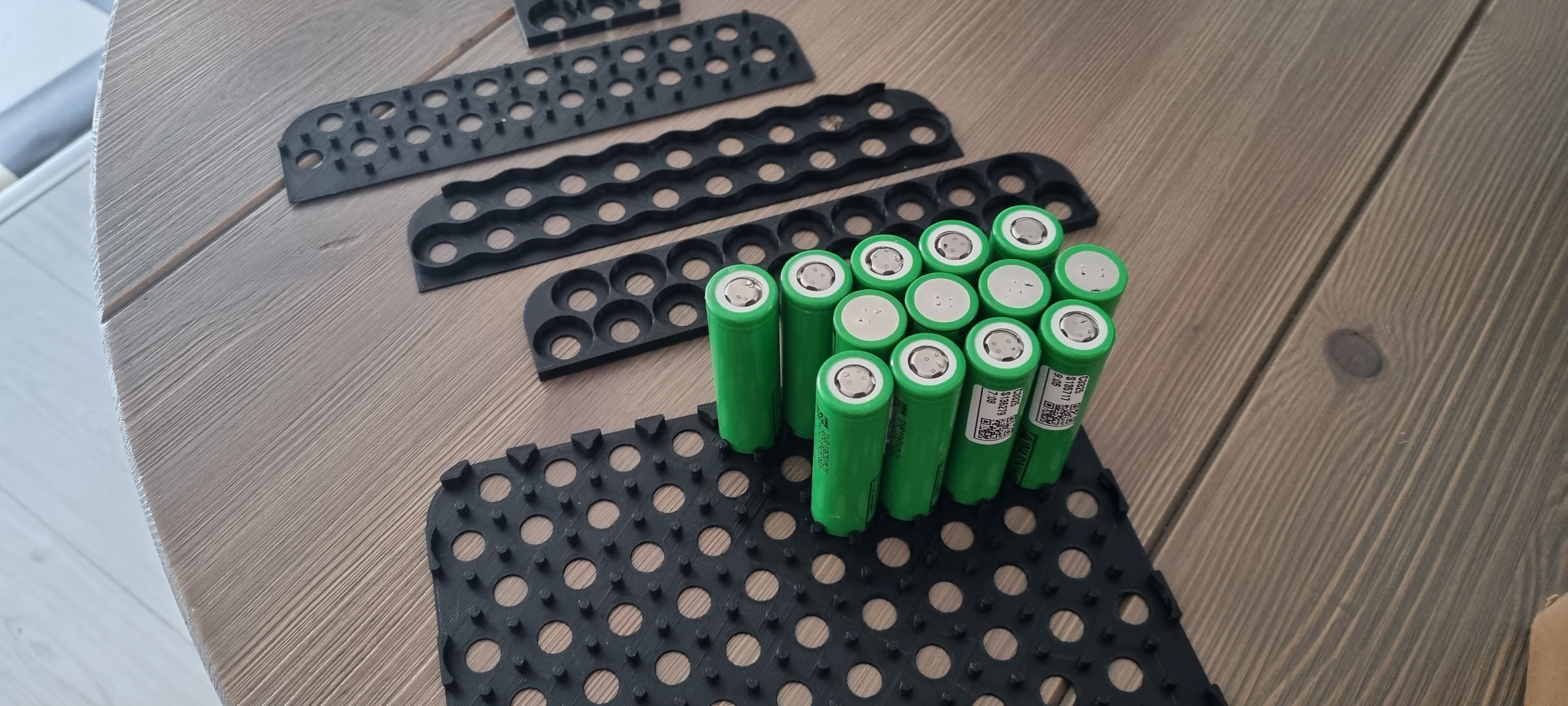
Nice pics
I put a link for balancer board last year but I think no one has done it yet , and it will probably take forever to do the job
For the case 004 , yes you can fit the cells without full spacers just separating them in the row with 2mm , find this solution at the time but did not do it and you have some room in height to overcome the round bottom side ( rising the all set by 5mm)
Looking at your printed spacers are you sure you can fit 14s12p in that case ?
The individual cell fusing works great. I have built 4 of these batteries and after a year they are all working well.
I think the balancer board is low risk, unlike the very dangerous BMSs. But, I also think it isn’t worth adding.
My understanding is balance boards work by discharging the cells with the highest voltage untill they all match the cell with the lowest voltage. And the max discharge current is usually around 100ma. If we’re talking about a 14s14p battery with 3.0ah cells, that’s means each cell is 42 amp hours. It would take 10 hours to discharge (balance) just one amp.
Not sure I understand what you want to use the balance board for? Keeping the cells balanced during use, or balancing the cells while charging? Would this balance board be directly hooked to the battery and left attached permanently?
If you use a balance charger during charging (like the iCharger X8) then the battery will be fully balanced by the charger and the balance board isn’t needed. During use the battery will not get out of balance enough to notice unless you have a bad cell, and then when you balance charge it during the next charge cycle you will see this because that group will need less amps to charge than the other groups. So again, balance board not needed. And if you leave the balance board connected all the time I would fear that it would slowly discharge the battery during storage?
Just sharing my thoughts on the subject. Lmk if I missed the point all together.
Looks the same as the active balancer i have intended to use on my sup motor. Not tested yet. Will also not use a BMS due to safety, but my plan is to use the balancer at storage and while charging, but will remove it when using the sup(this also for safety). It can not do anything during the short time battery is discharged anyway. It is probably very slow, but when finally cells are in good balance, dont think it has to work that hard . Will use a simple automatic charger( auto cut off when voltage is reached) but that has no balance function.
@ Alexandre; well they should fit. Originally I designed with the 18mm of a "18"650 cell and the inside dimensions of the box (square). Should have fitted 196 cells. But…
The cells are in fact 18,3-18,4mm in diameter
There is a label placed on these used cells by the inspection company, which is almost impossible to remove. Thus randomly the cells are 18.5-18.6mm in diameter.
I like the idea of having a small gap between cells to make sure the outside (GND’s) are not touching.
Well I ended up making a spacer for 180 cells, of which I will used 14 * 12 = 168. (13*13 = 169 would also fit).
The remaining space will be used for the inside of grummets/connectors and an additional 200A fuse.
Due to the size of the printer bed, it is made out of two parts. Which should connect with mini dove tails. I tried different holder shapes, but pins with a small angle to them have a nice alligning function and are the strongest (3D printed).
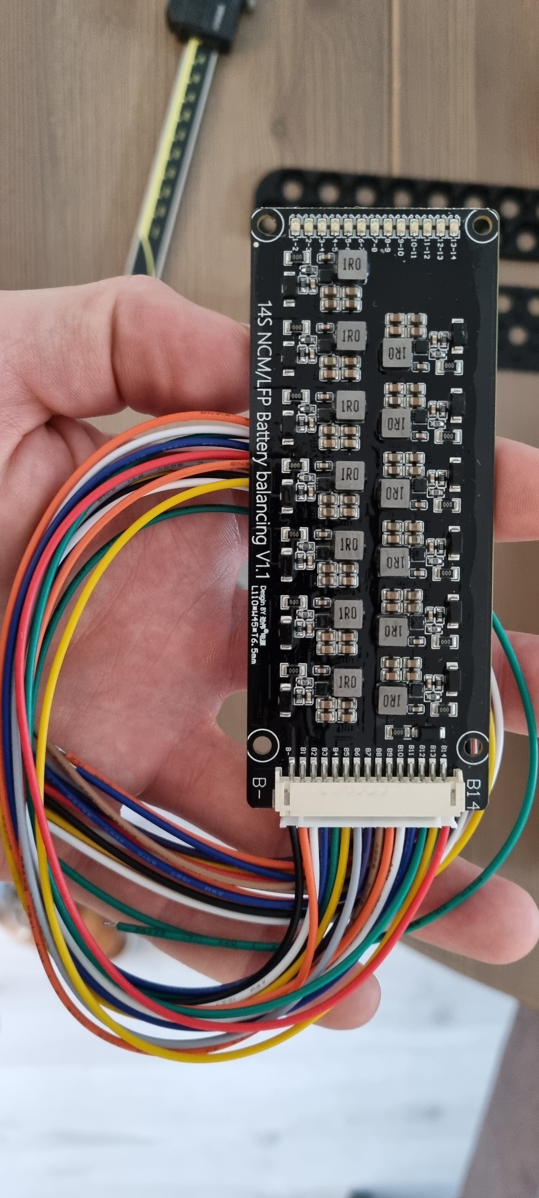
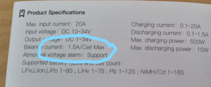
@ Flightjunkie; good point you are making. So I had a look at the IDST Q8 manual, which states the max balance current is 1,5A/cell.
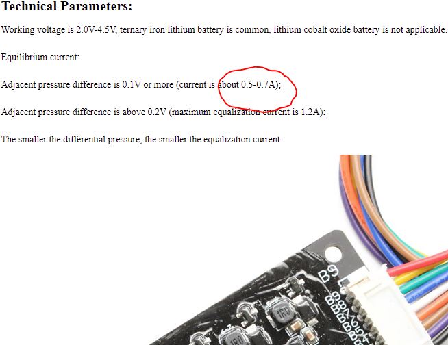
The balance board has a max balance current of 1,2A/cell, which is relatively close to the charger. I see a couple of fat 1Ohm resistors on the board which I asume will indeed burn the difference to balance.
Now I have two options:
Permanently attach the balance board (thus inside the enclosure). It is possible that it will not keep up during discharge, but it will do its job during charging.
Make two “7s12p” batteries and use connectors like you did to balance them externally with the charger. (could also do this with the balance board).
I like option 1, thus only two wires going in and out of the battery box. But I need to test this under load to see how hot the balance board runs and how (un) even the cells turn out to behave.
The balance bord will discharge the highest row to the lowest … all the time , so not the best if something goes wrong …
The new icharger x12 is out : 12s , for 14s still need to split the pack into 2x 7s
But another idea , is to do a 14s pack but to add a charge plug in the middle , so you can charge one 7s side at the time ( even if the rest in weld together ) so only 2 bus bar , 3 charge leads , pack charged in two times
Thanks for the input! I really like all the feedback I receive. I will add the “fatter” charging lead between 7 and 8. So that ability remains.
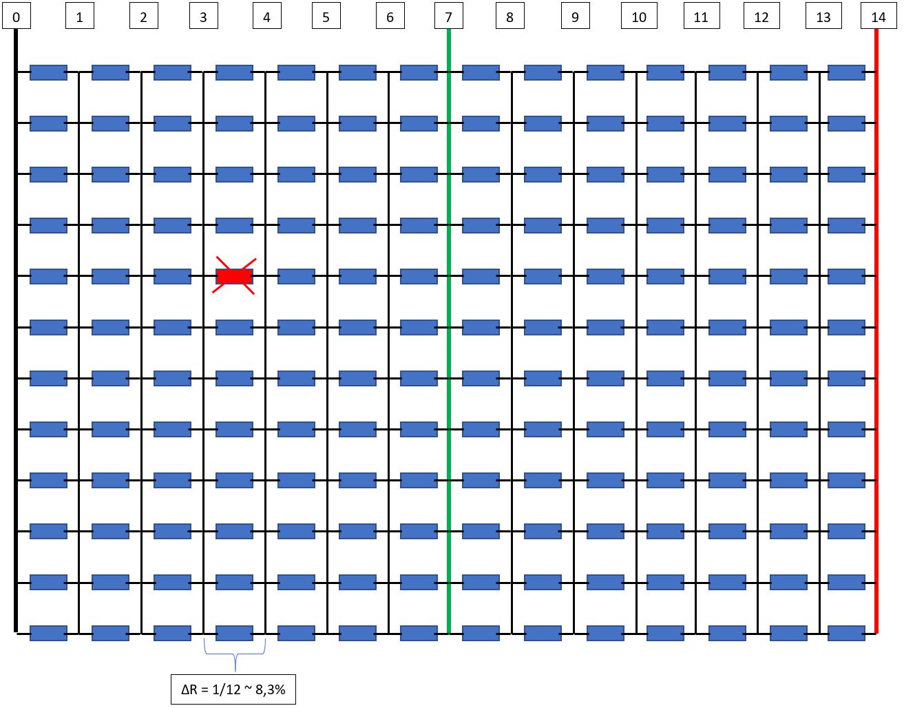
Well for time that something goes wrong I have the individually fused cells. That should help if one cells quit doing its job. My idea is that the if 1 of the 12 parallel grouped cells goes bad, the balance board is still keeping up while charging the complete battery pack in series. Let me try to illustrate below.
Theoritaclly the resistance of this parallel group now deviates with 8,3% with the rest of the pack. If I charge it with 4A in series. The deviation of one “bad” cell, would result in 4A * 8,3% = 0.332A of balance current. With the ability of the balance board to balance 0,7 A under preferred conditions, gives a Margin of Safety of 2,1. (1,2A gives a MoS of 3.6). This leaves room for individually cell deviations, faster charging etc. But again I have to see if it will work.


 Once you have several days of read time things will start to make sense.