Good point! I fused all of my balance leads where they hook to each cell after a fire due to shorted balance leads!
Right battery balance leads fused, left battery prior to adding fuses.
Good point! I fused all of my balance leads where they hook to each cell after a fire due to shorted balance leads!
Right battery balance leads fused, left battery prior to adding fuses.
Your second pack looks tidy and polished 
I’m using littelfuse pico 2a fuses on my balance leads, they’re as small as a resistor.
The plastic enclosure I purchased on aliexpress was way too flimsy, so I’m going to build an acrylic case like yours. Have you secured the battery so it can’t move, such as when it’s upside down?
I think I’ll cut some threads in the corners to hold the lid on. I’d prefer a soft gasket type of glue/seal that I can easily remove for maintenance.
Thank you!
My charger balances at up to 2A current. So I used 5A fuses on the balance wires.
The lid touches the top of the battery. So, it can’t move around. Nice snug fit!

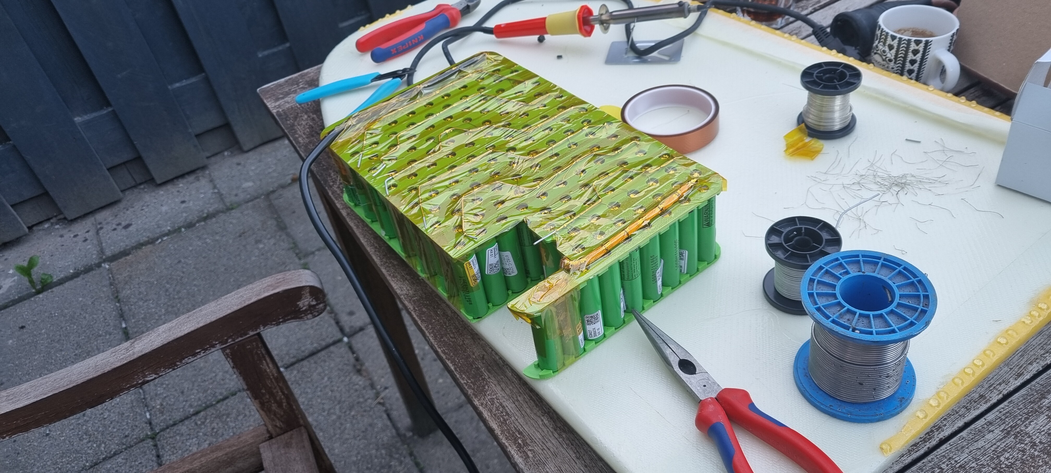
So I have made the battery pack and used the fuse wires directly to put then in series. The parallel groups are done by a thicker copper wire, also used for balancing. The fuse wire is 0,4mm OD, the balance wire is 1,5 OD.
Currently testing the balancer board. The battery holders are replaced with ABS instead of PLA, and PI tape is very nice to properly secure everything, leads wires etc.
I really like your individually fused battery disign! In a reply to someone else you said that it would be better to do a 12s14p in your opinion. Could you elaborate on that?
I also came across this product to individually fuse your cells but I’m not sure it can handle the loads, although in the description they mention they will have one that can handle more amps soon.
Hi. Thank you.
The “S” group is what gives you your pack voltage. The “P” group is what gives you the amp hour capacity and the ability to pull higher amp loads on the pack. I went 14s because I wanted a 56v battery pack. 12s will be a 48v battery pack. Less voltage means more amp draw and this requires larger wire size and generates more heat. But, there are many more options for speed controllers at 12s. Not as many can handle 14s. I love the Trampa 75/300 VESC but it’s expensive. So, I guess people prefer 12s because it’s a cheaper build.
Lift and Fliteboard both use 14s14p for a reason. My battery out performed theirs. Same specifications, but I used larger wire size so mine is slightly more efficient.
I hope this answers your question.
As far as the individual cell fusing goes. I didn’t want to spot weld and I wanted to be able to easily change a bad cell. I have only had one cell go bad so far (in a year) and the fuse wire did pop. Battery performed well because this cell was disconnected so it didn’t drag down the rest of the battery. I’m very happy with this design.
VERY helpful! Thank you for your reply! I’ve been leaning towards the 14s14p with the 75/300 but wanted to see if there were any advantages to the 12s14p. Batteries are soo expensive! Thanks again!
Hi Flightjunkie, what an awesome engineered battery pack! Thank you for sharing your journey, tests and very well reasoned and detailed build. I like your determination early on in the thread, and it looks like experience has proven you right! You described the conformal coating on the connectors. Do you use any conformal coating (and yes have to ask corrosion X) inside the waterproof battery housing? E.g. battery terminals, bus bars, fuse wires etc? Are the dessicant bags just for the first build or do you use still use them on all 4 packs you have build? Is the silicone grease and shrinkwrap for the connectors outside of your box? Many thanks
Hi. Thank you for the kind words. I’m glad my build has been of benefit. 
Everything is conformal coated. Conformal coating will block an electrical connection. So, be careful not to get it on and contacts or plugs, or things that haven’t been connected together yet. The 18650 batteries, once all connected together, the entire battery is coated it +4 coats of spray on conformal coating. Any moisture in the waterproof box will corrode the batteries, and solder connections, and copper wire. So, I coated everything. I didn’t use any CorrosionX in the battery. But, if the battery ever gets wet you must wash the salt water off, clean it with rubbing alcohol, then soak the whole battery in CorrosionX. Doing this will save the battery if you do it immediately.
The desiccant beads are required, or the humidity in the box will cause it to fog up.
Hope this answers your questions.
Thanks, that was an excellent answer. I think this thread should have prevented at least 1 or 2 accidents already… For my 3d printer, i am also using dessicant and this hygrometer in my filament drybox, i think it will work well in the transparent battery case. Battery lasts around a year and seems accurate:
https://www.amazon.com/Veanic-Electronic-Temperature-Thermometer-Hygrometer/dp/B07GNMKYCZ
Just to confirm my understanding: no conformal coating on connectors mating surface. Douse connectors in corrosion X, heat shrink, conformal coating on non mating surface and silicone grease on connectors outside of the box! Many thanks
Yep! Good luck with your build!
Hi all.
I’m about to start my battery build with samsung 50e 21700 cells. I chose to use a spot welder for the sake of time, i am planing on not fusing my cells but i will definitely fuse the main bus bar wires.
do you think i’m fine not fusing each cell? i really like the idea of using the fused nickel strip that patrickgrem showed, but there meant for 18650’s.
Yea. You’ll be fine. Individual cell fusing is a small niche market. None of the manufacturers make batteries this way because it’s too labor extensive. Well, except for Tesla. All their car batteries are individually fused on each cell.
The cost of the venerable 30Q has really gone up, and to keep the battery pack affordable 21700 seems like the way to go. For this reason, we need to be able to recalculate the fuse wire size (Unfortunately not everyone has your testing set-up). So far I have found 3 interesting links on the web:
https://electricguru.in/page_view.php?id=29
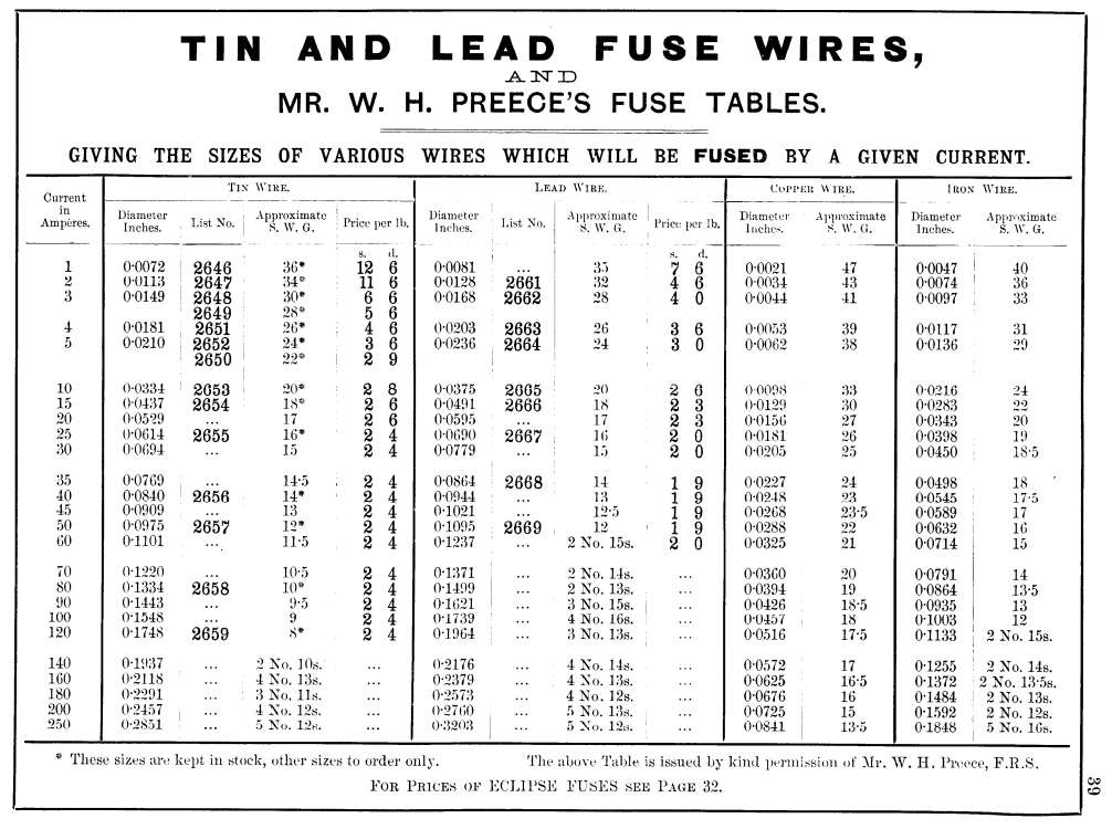
and also this antique table from the early 1900s:
The fusing current in Preece’s law is where the heat input from resistance equals the heat loss from radiation or convection.
The discrepancy is with your testing (which I don’t doubt, the video was quite informative.) Where the tables say that melting should be expected at around 10A for the 30AWG copper cable, you found that this would happen at 25A in practice. So the fusing current from the table should be seen as the max current that the wire can carry safely without melting (my interpretation).This seems to be consistent with your observations that the wire will stay cool until around 10A, start to warm up at 15A and melts at 25A. Please let me know if you have other experience or advice interpreting these tables.
Also, while the 30AWG fuse wire seems to be a good fit for your application, I still get a significant voltage drop:
With 0.5 inch per fuse, and 2 fuses on each size of the battery I get a total of 0.5214=14 inch of 30AWG wire.
When using 150A as the battery load (from your thread), and 14P you get around 10.7 A per 30AWG wire.
For 30AWG copper wire @ 35C I get a resistance 0.3580265748 Ohm/meter
(add 4% to 109.127 Ohm/1000 ft for imperial)
Sources: Copper Wire - Electrical Resistance vs. Gauge and
https://www.cirris.com/learning-center/general-testing/special-topics/177-temperature-coefficient-of-copper
Using V=IR I get a voltage drop of 1.36V. For a 58V battery that is 2.35%
I know you are trying to get the voltage drop of the entire system to below 3% but that means there is less than a percent left for the remaining components. I know you used 20AWG on the first and last row, but would it make sense to use 20 AWG on one side of each of the the batteries, and the 30AWG on the other side? This way you reduce fuse wire length by 50% and the voltage drop from the fuse wire is reduced to 1.2% and you would still have the same built in safety fuse for each battery. If my calcs are right, replacing 50% of the fuse wire with non fuse wire has a bigger impact on overall voltage drop than running 6AWG instead of 8 AWG in the mast. As always, thanks for your insights and awesome shares!
Hi.
Wow. That is quite the post. I’ll have to digest that for awhile! 
After a quick skim, things I can comment on…
Just doing the fuse wire on one side of the battery is a good idea.
The wire gauge chart is probably not accurate for such a short run of only 1/2".
The length of the 30AWG wire does not add up to being that long. The reason is because the cells are individually connected to the bus bars and the bus bars are connected together. So, it’s just the 1/2" top, plus 1/2" bottom. So, 1" total 30AWG, even when combined and looking at the whole pack.
It’s been over a year since I designed this. I’ll have to look at your post closer and think back to my design to comment further.
I also considered just doing the fuse wire on one side of the battery. I’ll probably due that on future builds.
Thanks for the indepth discussion! I look forward to seeing your battery build.
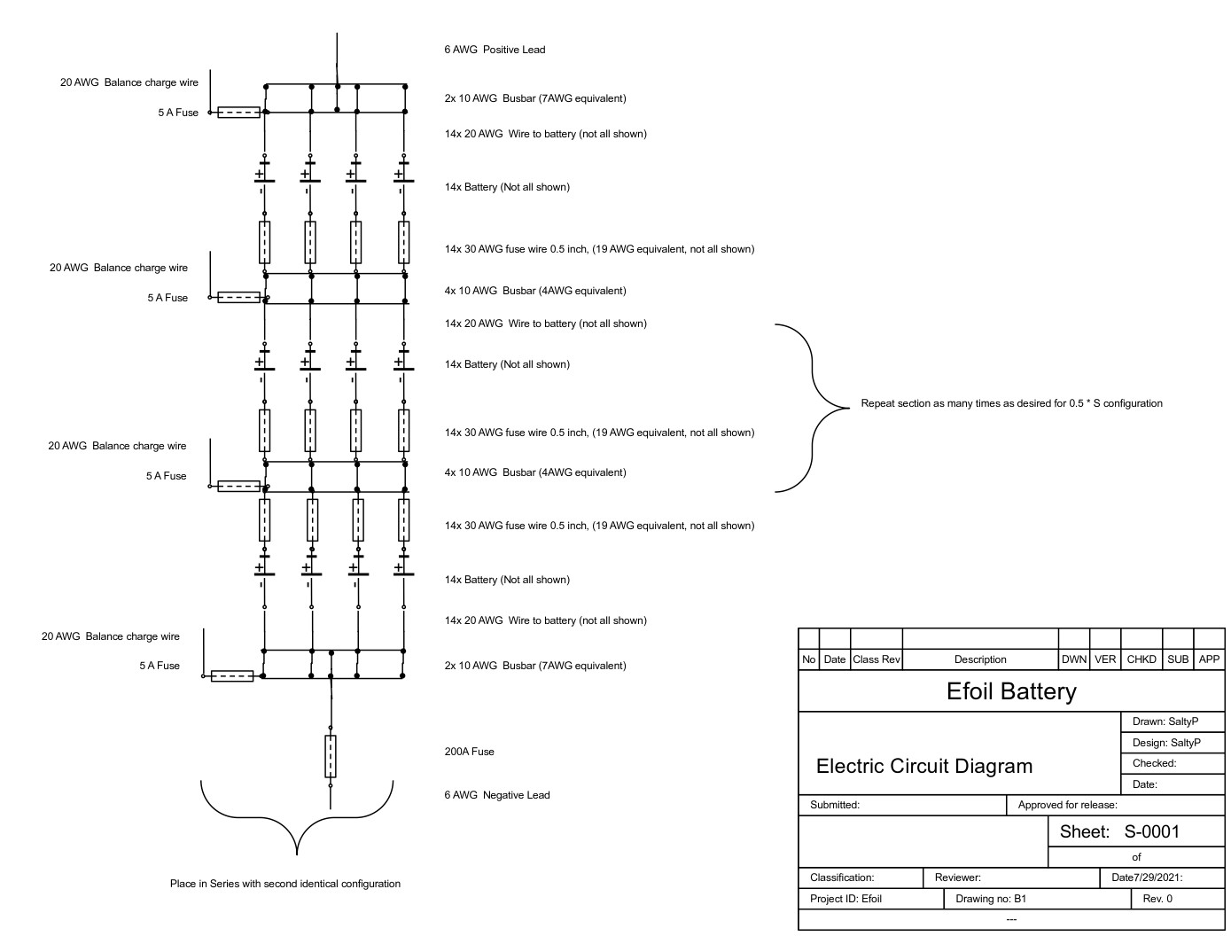
I don’t quite understand the comment “the bus bars are connected together”. Could you confirm the electrical circuit below (with the exception of the 20AWG connection wire to replace every other section) is how you have wired the battery (from the 2nd build on)? Many thanks.
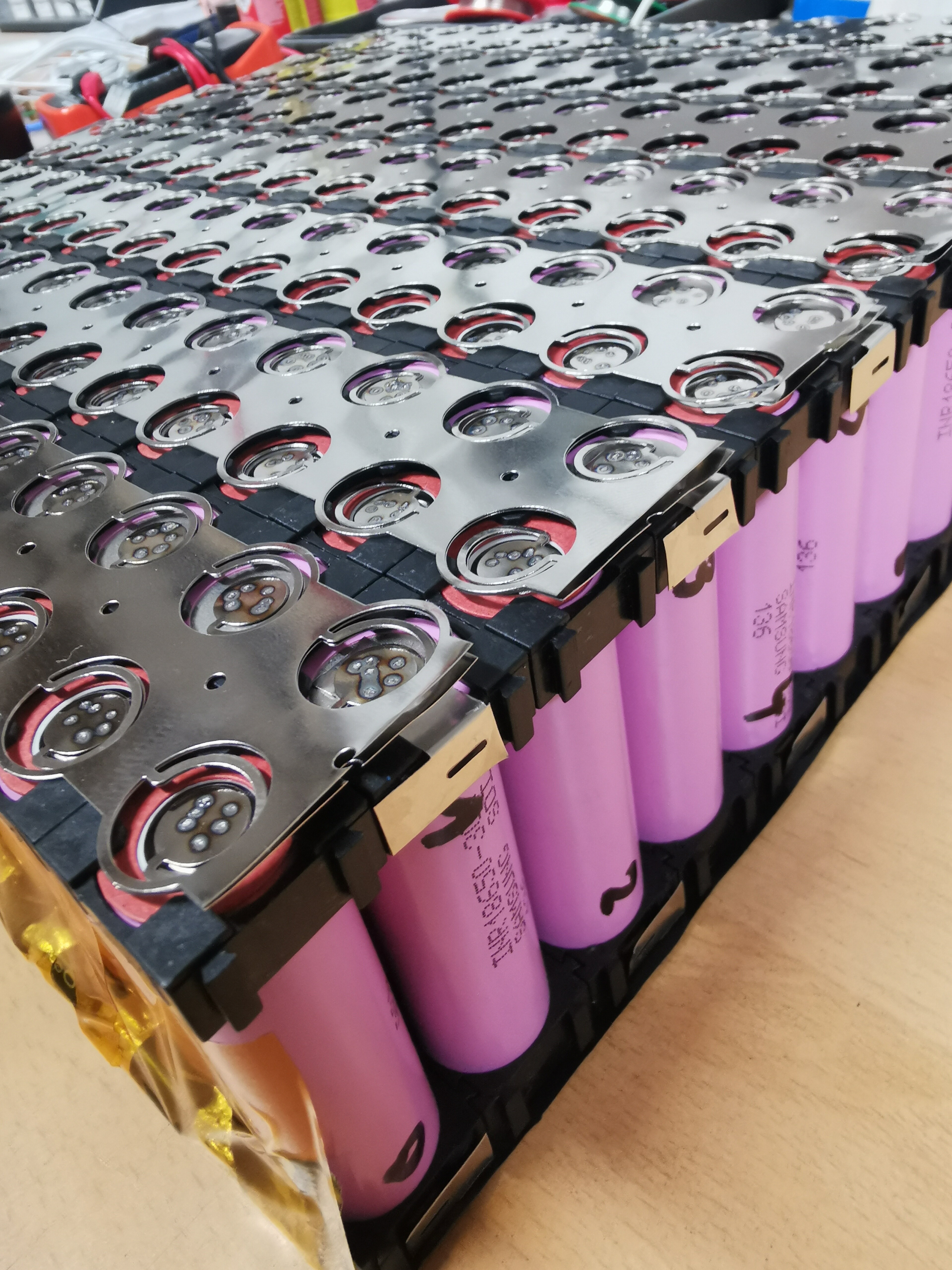
I’ve just finished building an 18650 Samsung 30Q pack with these nickel strips.
I had to spot weld two layers of nickel strips, since one layer will only do 3A continuous without getting warm and will blow fast at 8A per cell.
Now with two layers I have 6A continuous and 16A fusing. Times 14 cells this is 84A and 224A max.
I’m running the pack with a 200A Smart BMS…
Here are the pics:
I become depressed when I see the job needed for building a pack…
Anyway nice job to all people that have build their own pack
SaltyPaws - your calculations are interesting, with 1.36V drop in a 58V pack at 150A (with 14 parallel cells). It makes sense that the battery will voltage sag with an inch of fuse wire on every cell, totaling 30cm of high resistance wiring across the pack. All the other wires in our setups are chunky gauge to minimize losses and allow current to flow.
Runtime is precious, which is why I went for wide and reasonably thick nickel between my cells in a 6p pack, so as to avoid wasting power into heat. The losses would be much worse than 1.36V if I used similar gauge cell level fusing with 6p while pushing 150A.
I guess if you did have an individual cell fail with a short circuit, then a fused serial connection would prevent shorting the entire parallel row - but hopefully that won’t happen if we’re using good cells. It seems more likely that the balancing wires short onto each other, or a connector/plug shorts out - which can be mitigated with careful construction and a pico fuse where it the balance wire joins the cells
I can imagine some ways an individual cell could fail would include:
-salt water in the battery pack
-a piece of stray solder on the positive terminal
-a jagged square corner of nickel bridging the positive terminal to the outer can
Good quality +ve terminal insulators seem essential, and full battery waterproofing. I’m not sure I would trust a shrink wrapped pack which is only separated from the ocean with a single waterproof case.
Yes. That looks correct. The voltage drop of my pack is super low. I did a bunch of testing when I first built it a year or so ago. I’ve set my VESC amp limit to 250A and Towed foil boarders into the surf. No voltage drop issues.
I think fuse wire on just one side of the cells is a good idea. Nice improvement over my first gen of these packs.