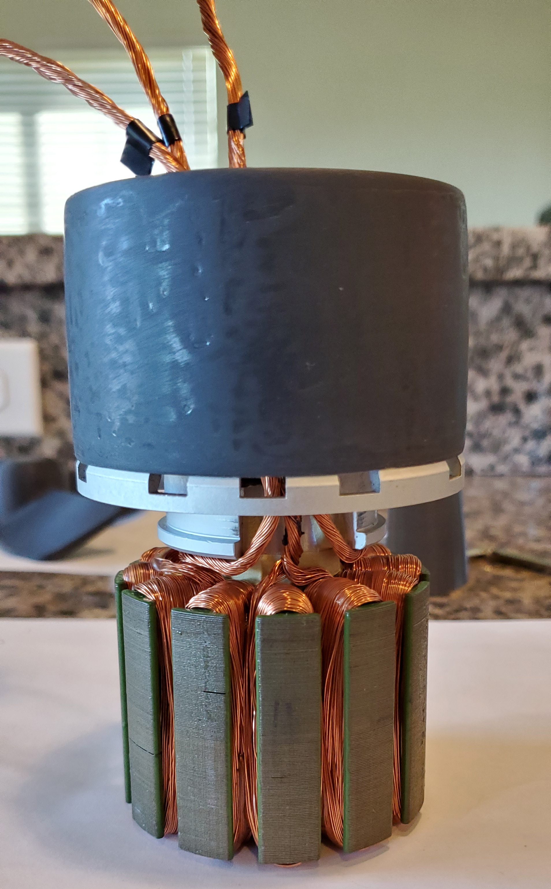
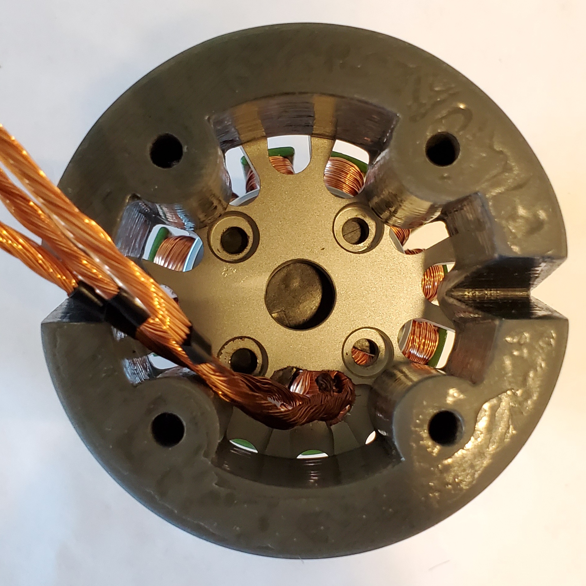
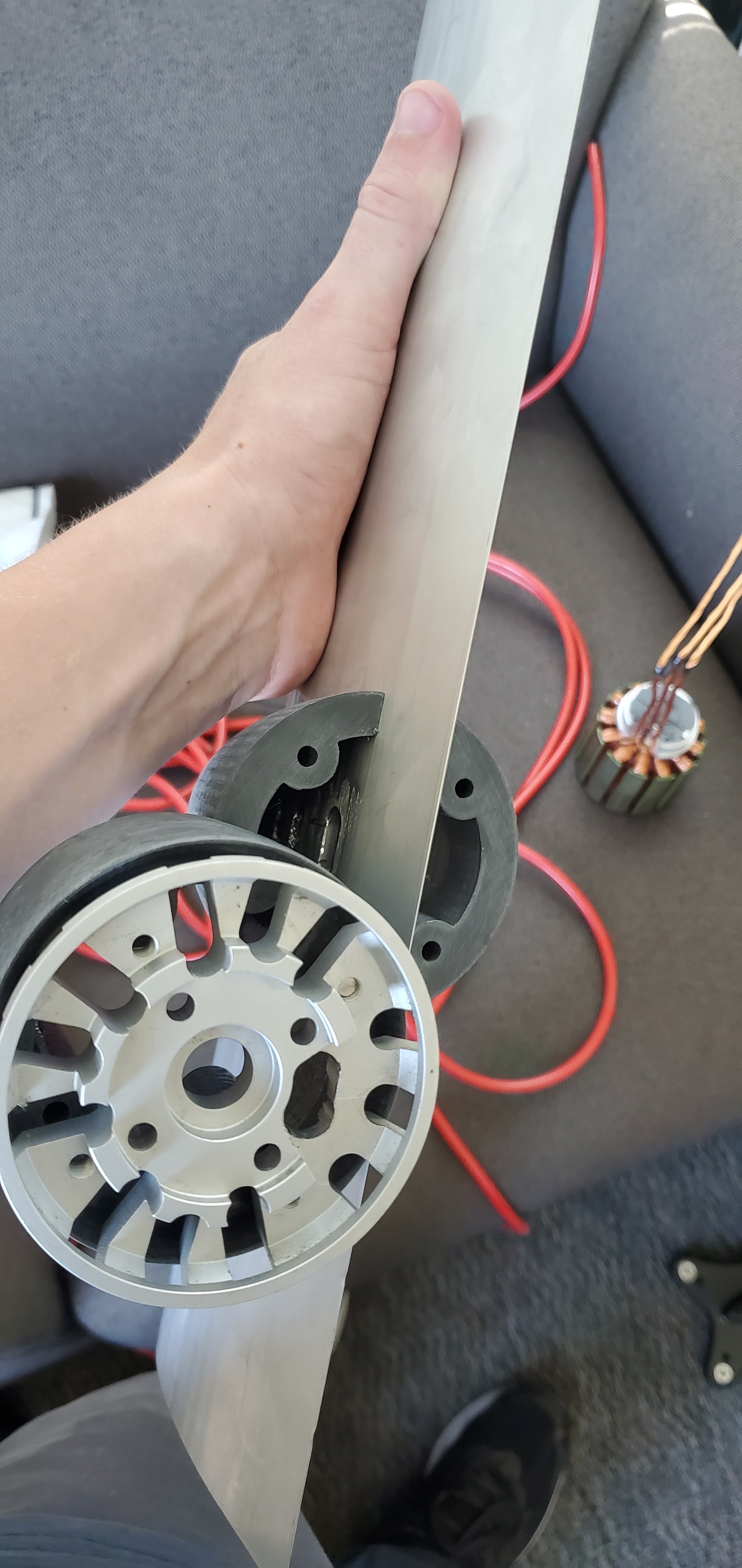
Today I prepared the stator for epoxy. I removed the wire insulation, covered the shaft bearing and threaded holes with e-tape and marked how far along the wires should have epoxy using the rear mast clamp.
The Maker Lab at SCU drilled holes in the motor cap for me to allow the wires to enter the clamp. They also 3D printed the mast clamp by V_S from the Volker build.
I will be filming the epoxy painting process for the stator and clamp parts. Stay safe and stay tuned!
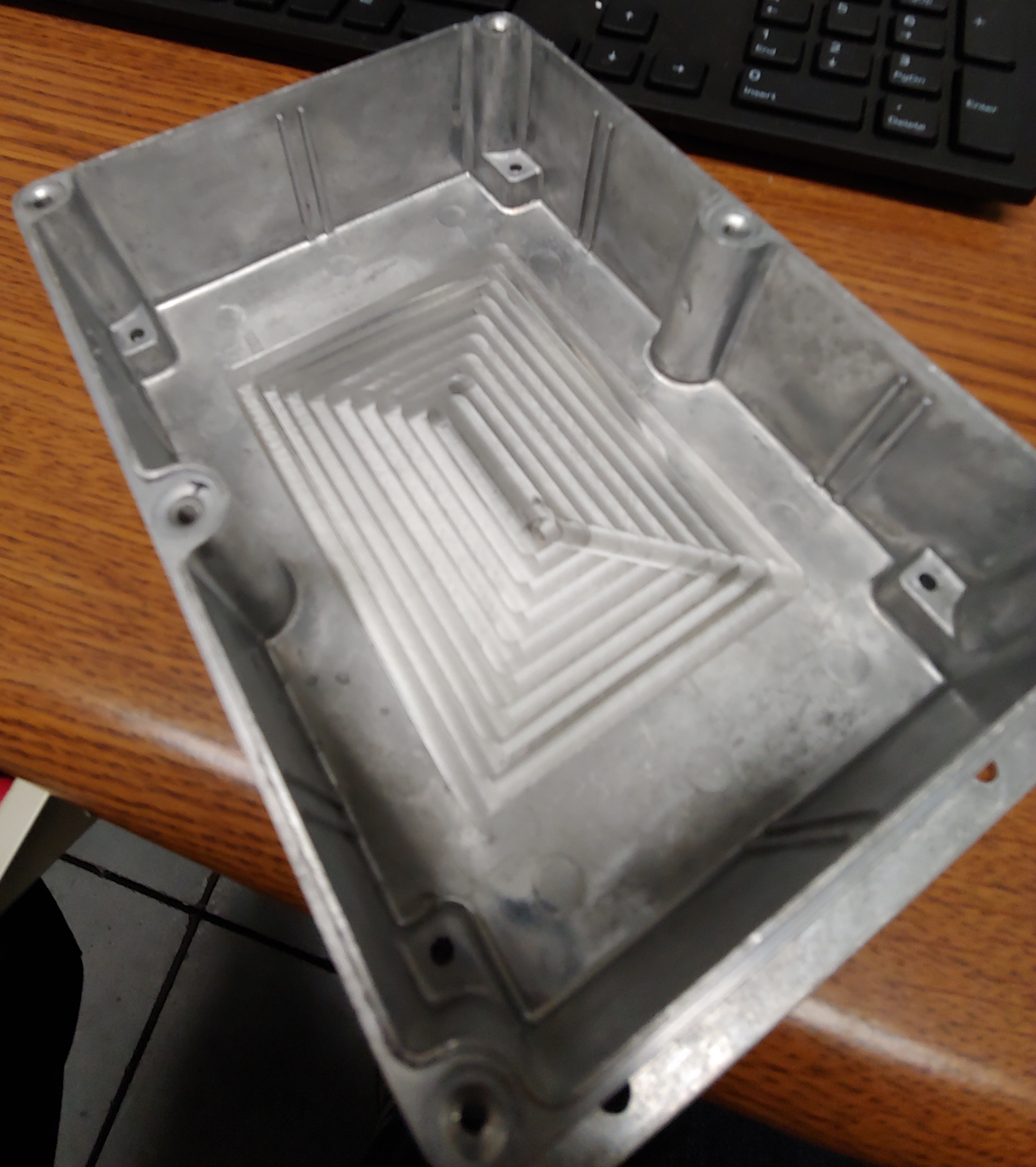
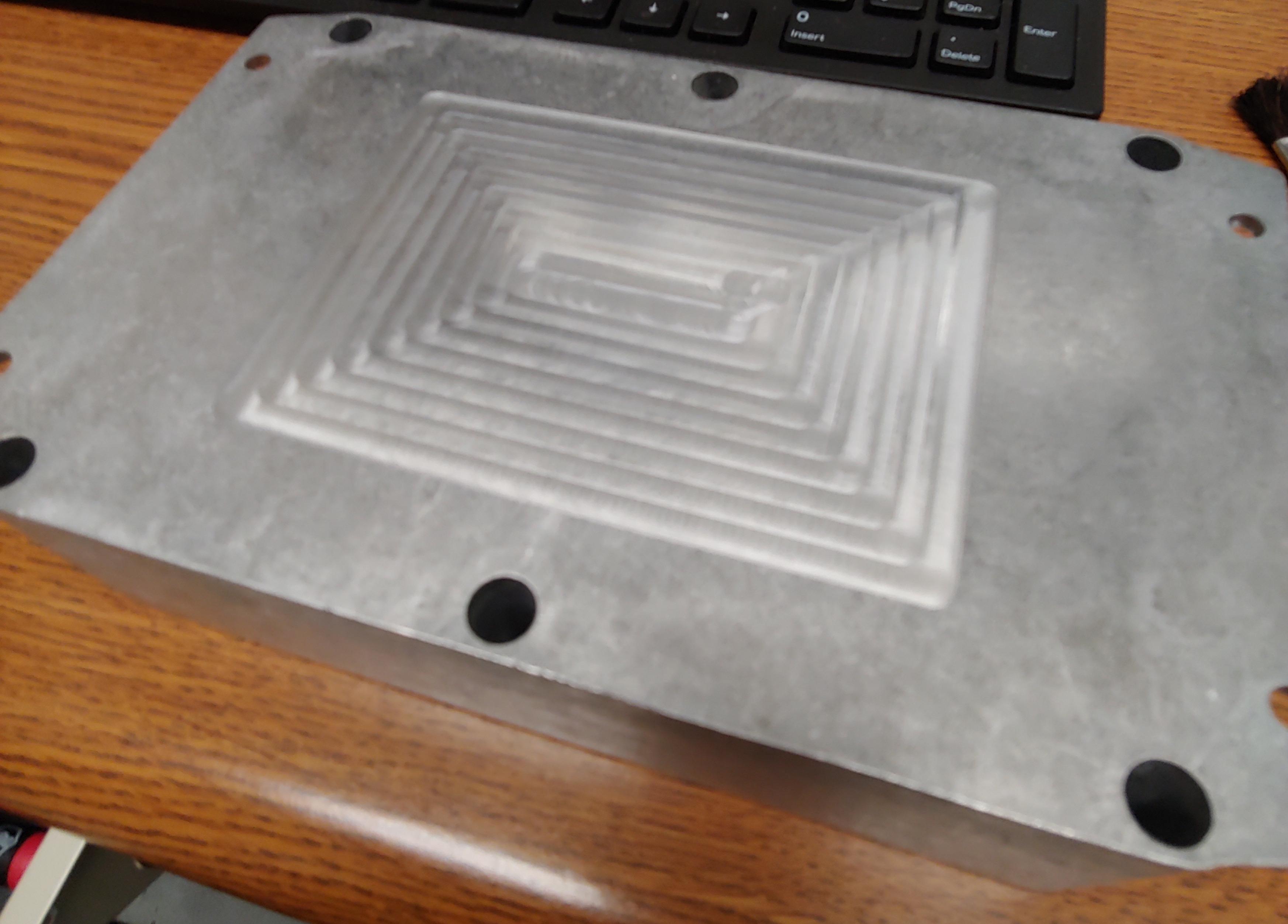
The machine shop at SCU is also helping me with this project. The shop used the CNC to spot face the inside and outside of the bottom face. The purpose of this is to improve thermal conductivity when mounting the VESC and heat sink with thermal adhesive. The original surface was tarnished and I was worried would cause thermal resistance.
It was very hot today in Santa Clara, California. Despite using 2:1 resin to hardener ratio I was interrupted while painting epoxy onto the stator of our 80100 as my cup of epoxy began to smoke. I acted quickly to reduce the internal volume of the solution and the reaction stopped. It was a low risk situation but nonetheless startling.
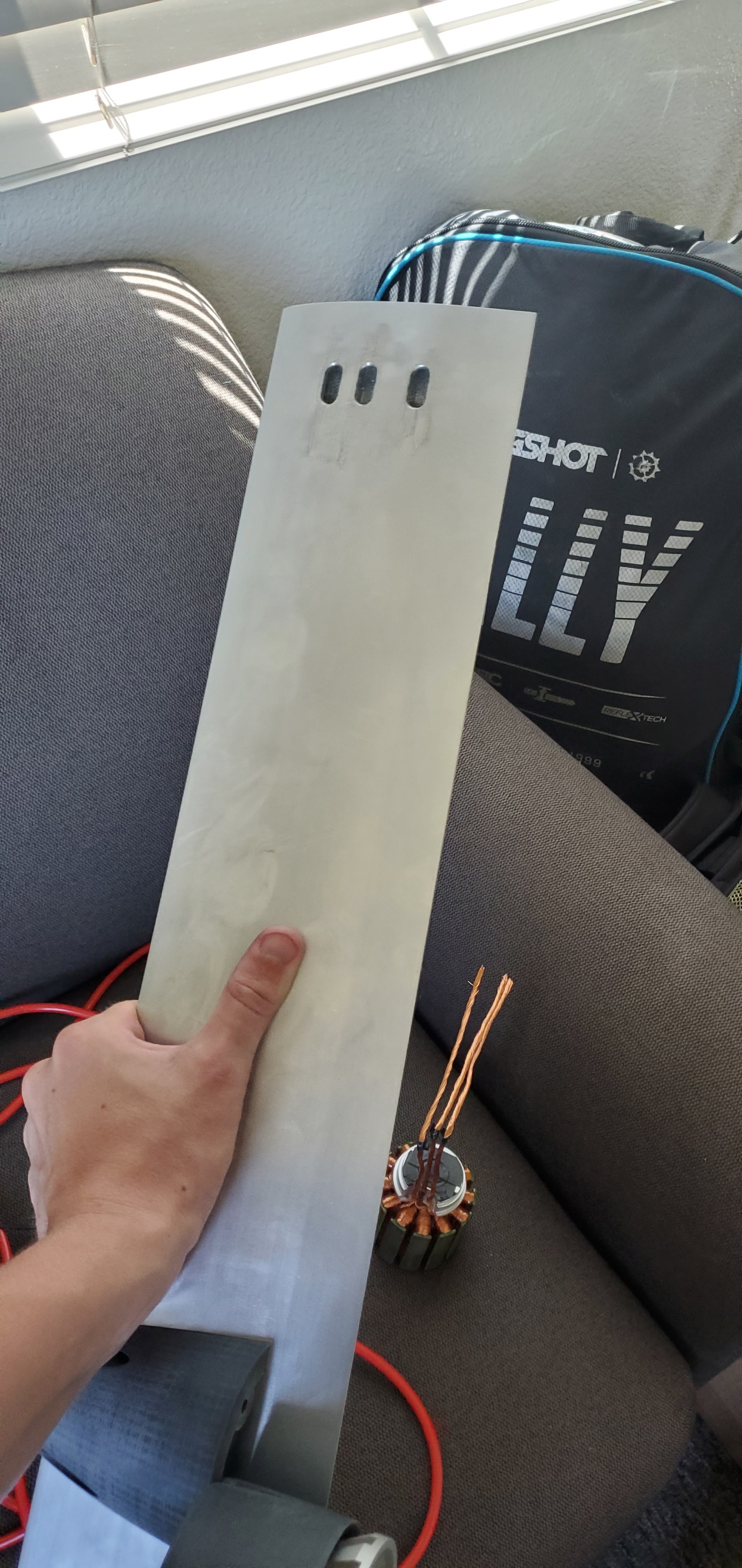
The full mast clamp has been printed in ASA. I will sand it and coat it in XTC-3D. There is a gap between each piece however it will need to be addressed in version 2.
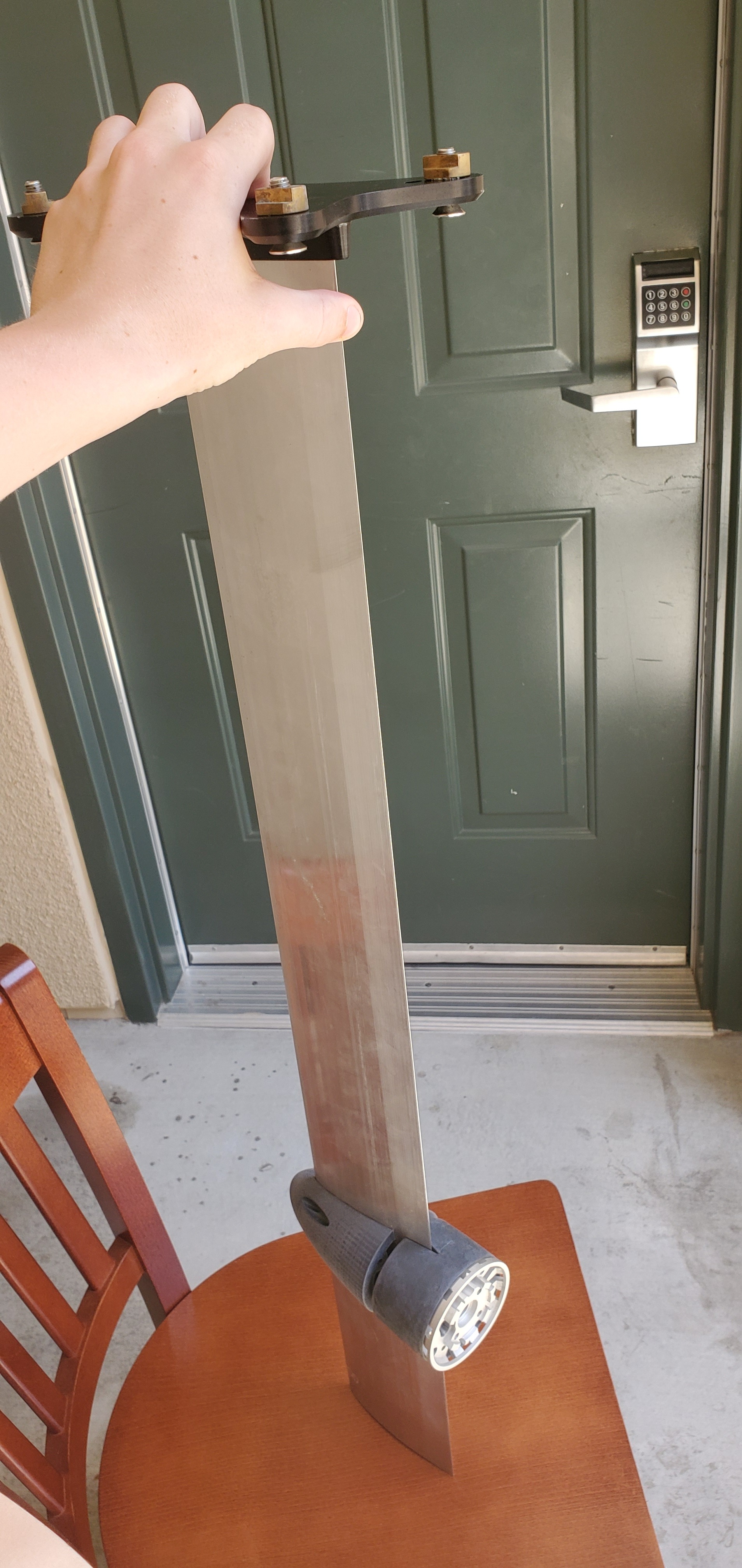
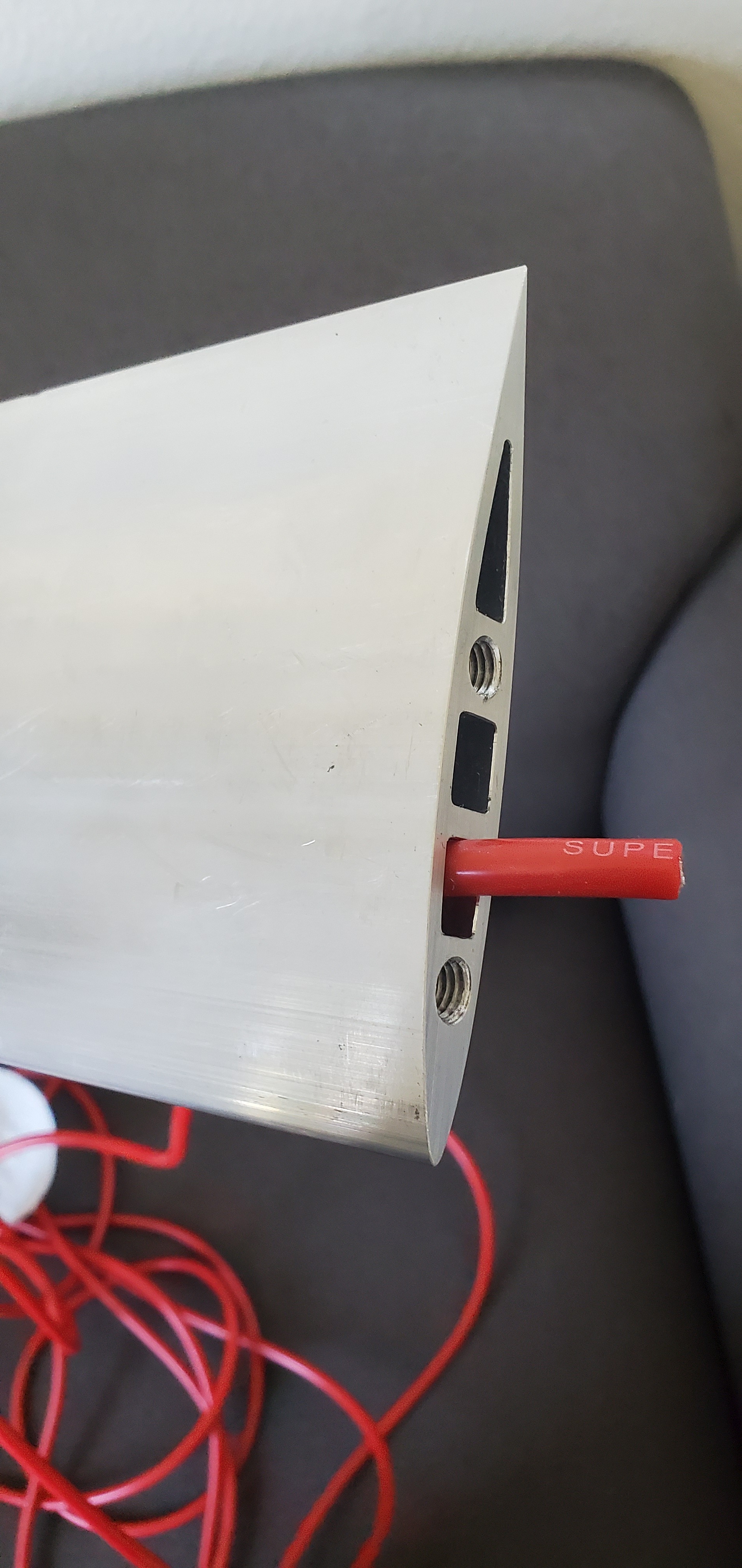
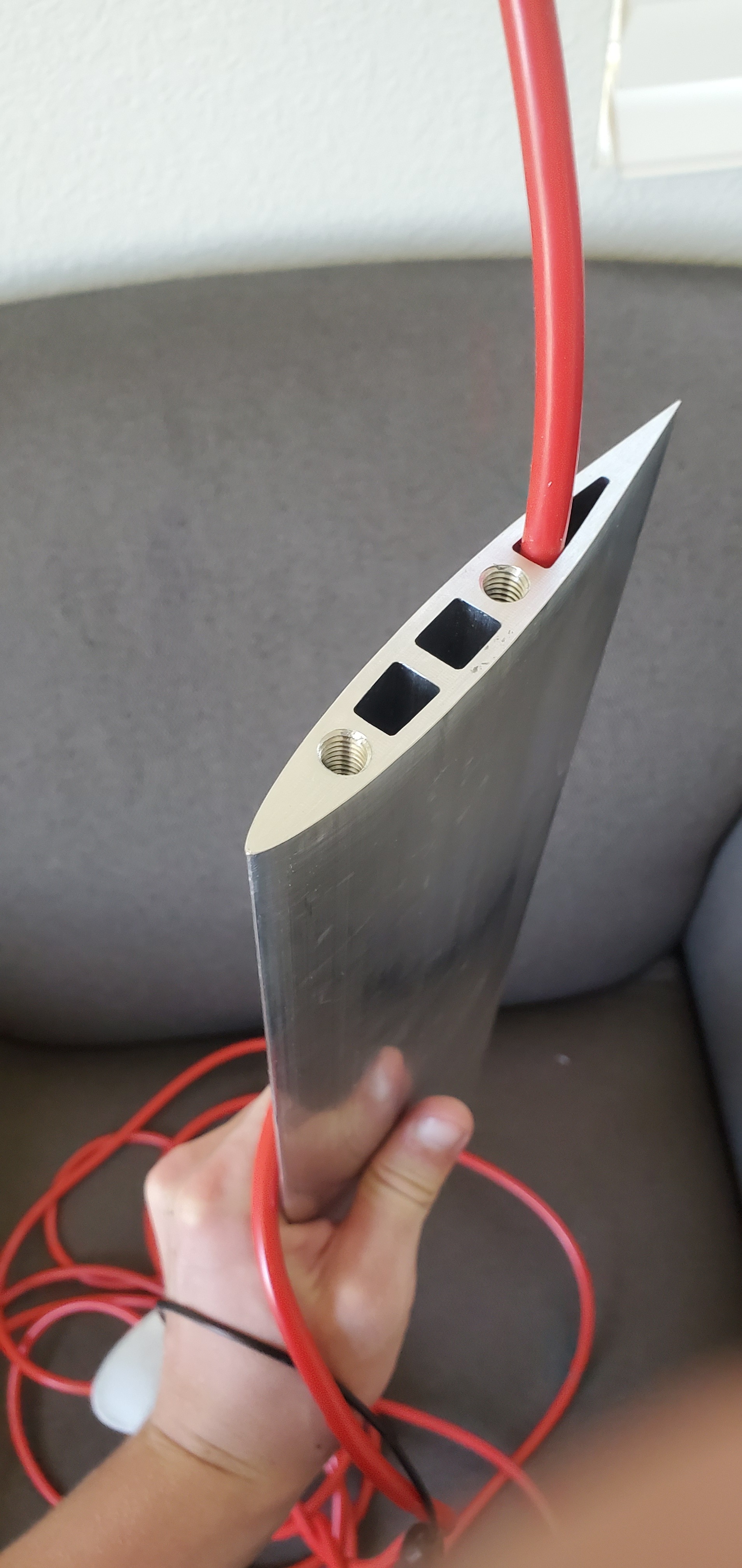
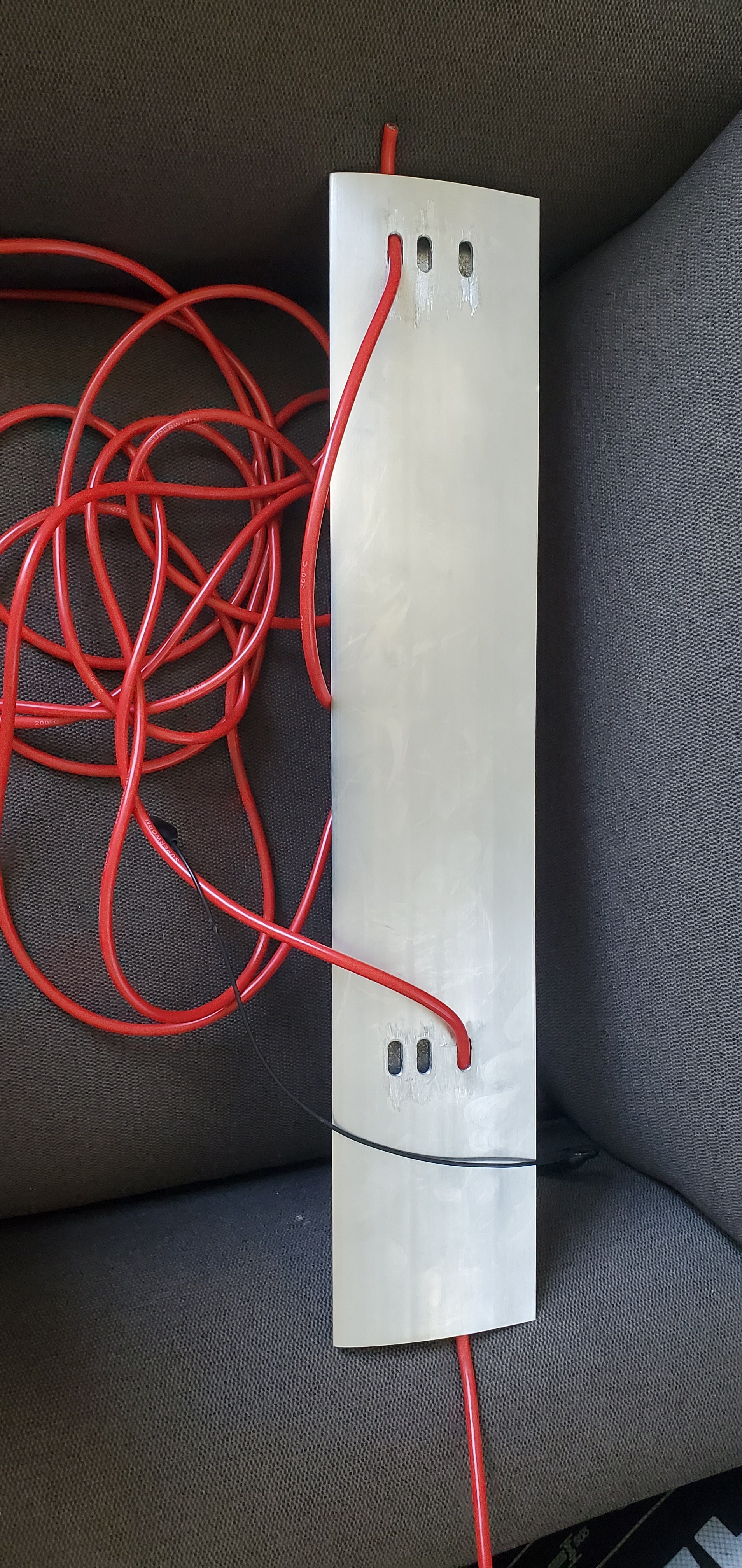
The mast was cut to 24" by the SCU machine shop. The holes in each end were tapped. Slots were milled for wires to enter the motor pod and exit near the top of the board. I am running the wires around the side of the board in this version. I hope to implement a more elegant solution in version 2.
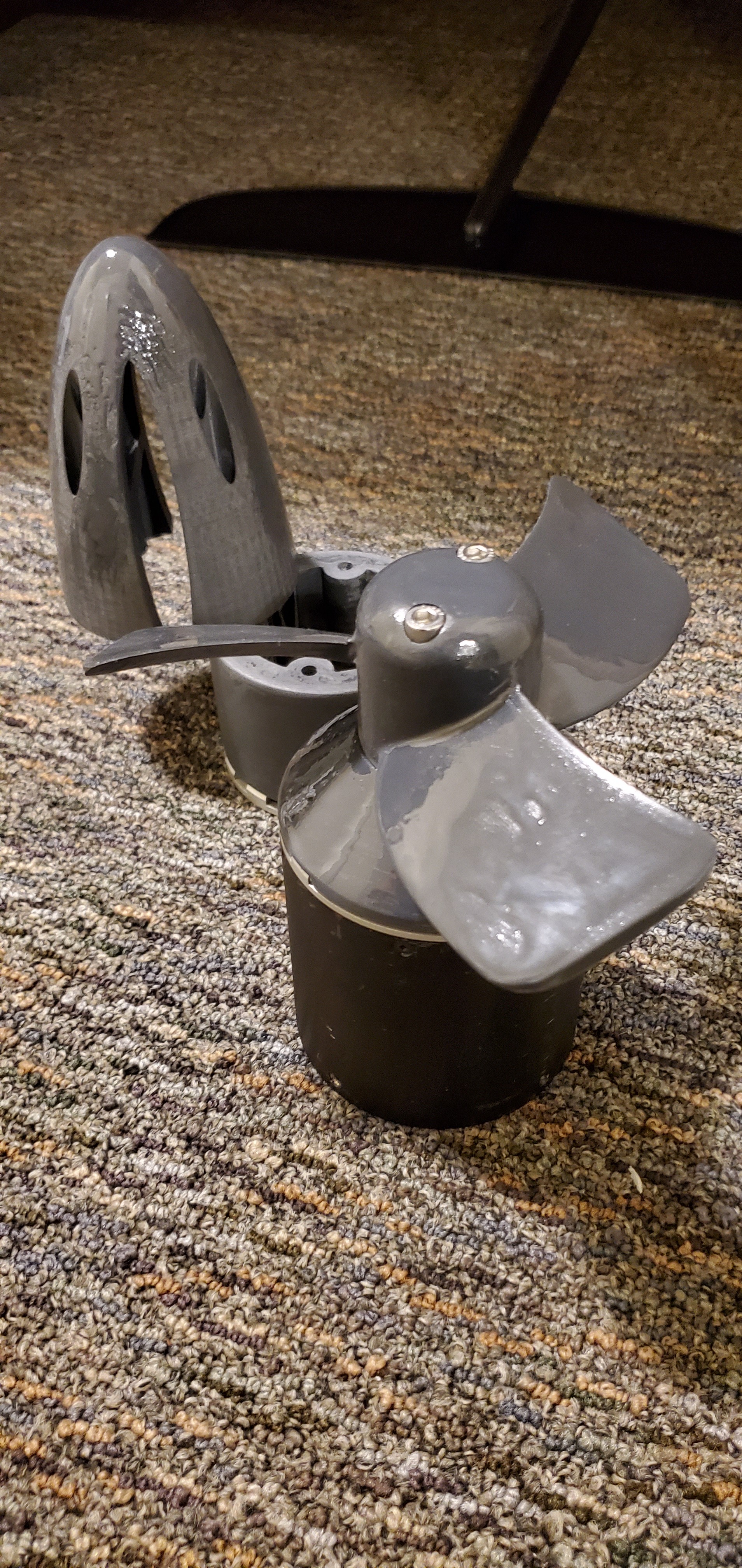
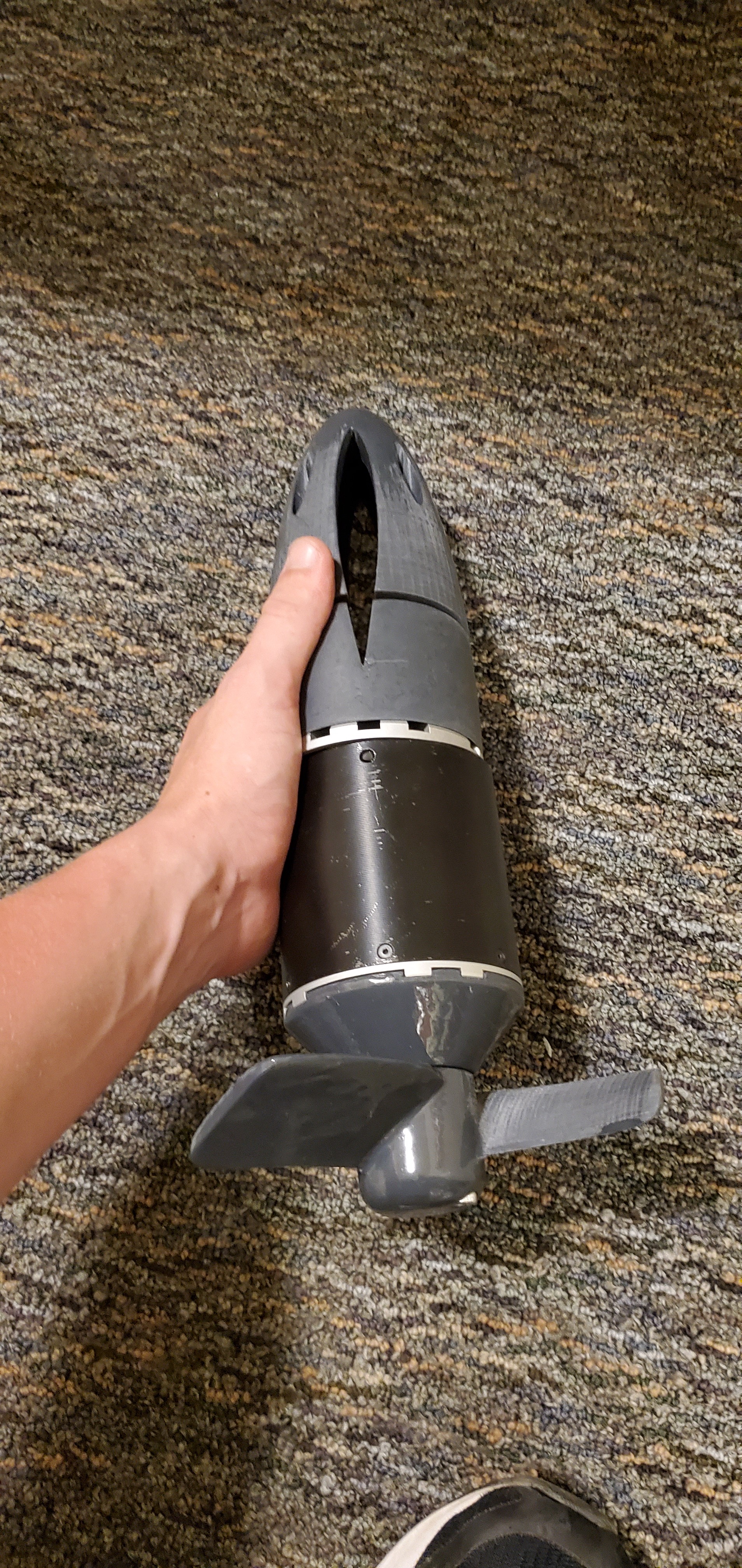
Thank you for sharing! I am sure the prop I have printed will work fine. I appreciate you sharing this 2 blade prop for version 2. I bet it works great. As mentioned at the start of this build we are very interested in data-logging with this project. I hope through this approach we can compare props with additional granularity beyond good and bad. Our maker lab is using all of it’s 3D printers to make face shield parts for frontline covid-19 workers. I am not going to detract from that effort at this time for an efficiency gain when our primary goal is a working prototype. Please continue to share your suggestions and I will make note to implement, test and report my findings at a later date.
Hello Peter
This is not my construkt of Prop , but he is realy good.
I have many print of props, but this one is only better then all. More Eta and fewer current, only not lost the speed.
it is really worthwhile to deal with this prop.
Best regards Frank
You’re right but, if you don’t have a nice transition between rotor and prop hub, water does and forces the amps to arrive in greater numbers
The ultimate tuning so far being the Flying Rodeo saucer-shaped boss whose diameter is not only adapted to the motor OD but also reduces vibrations.