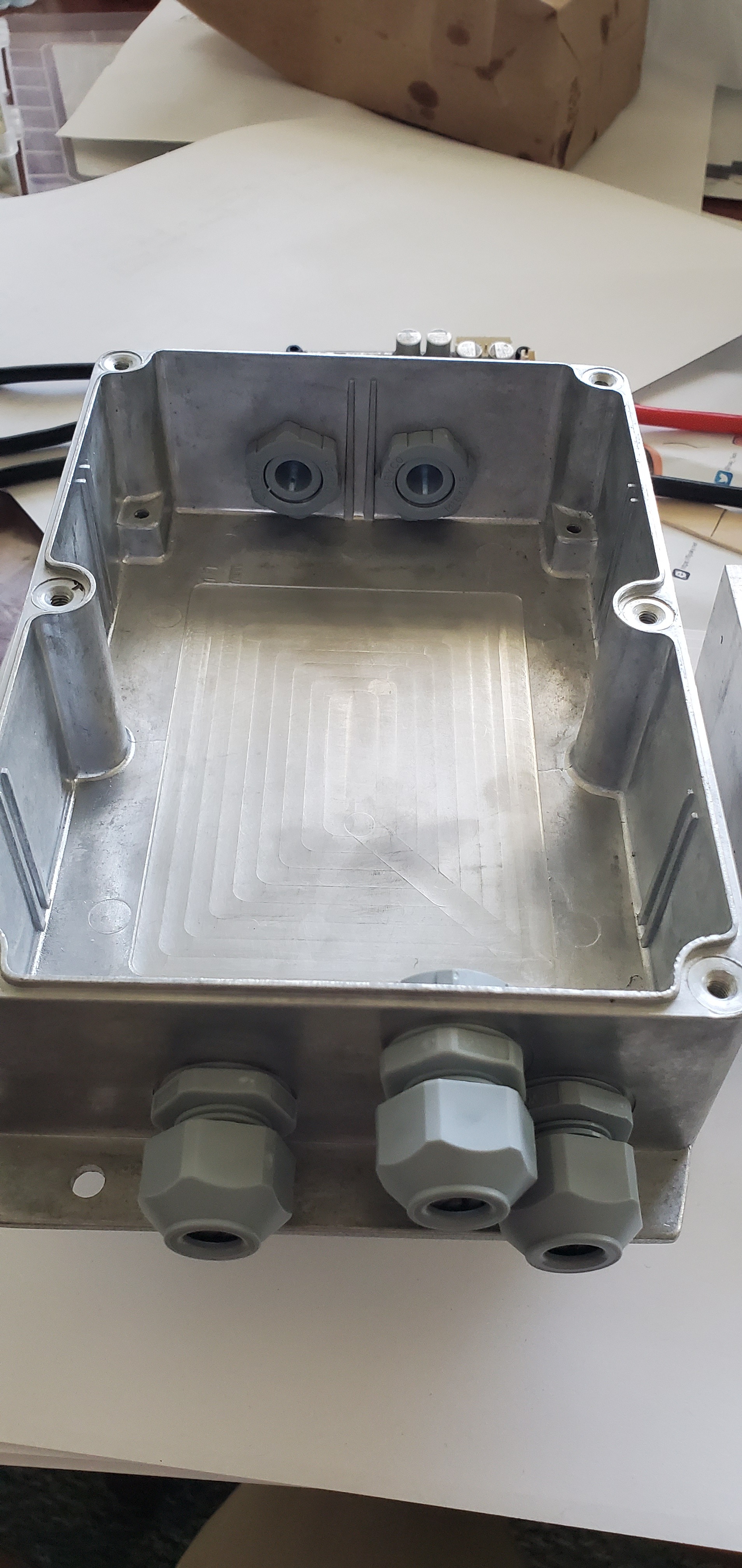
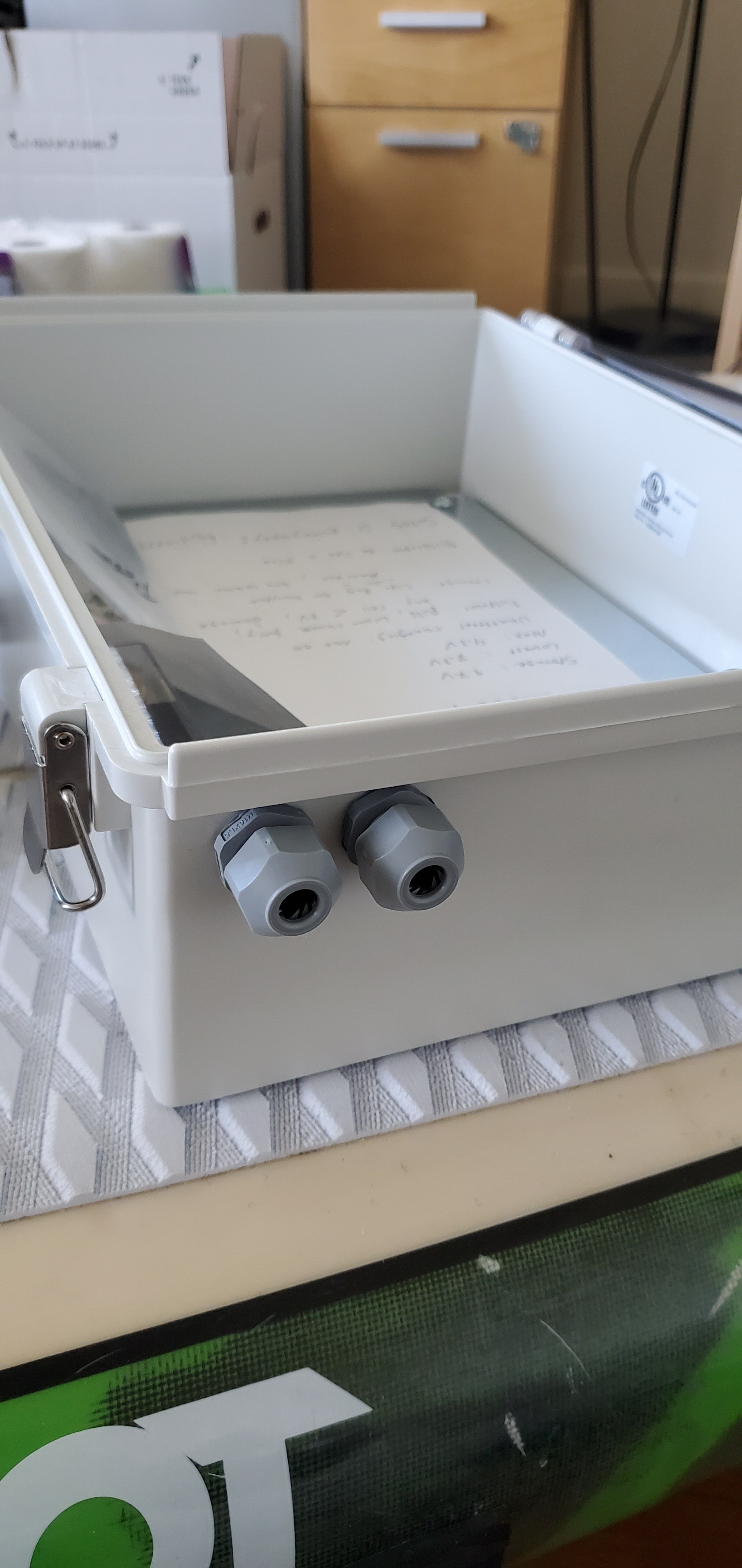
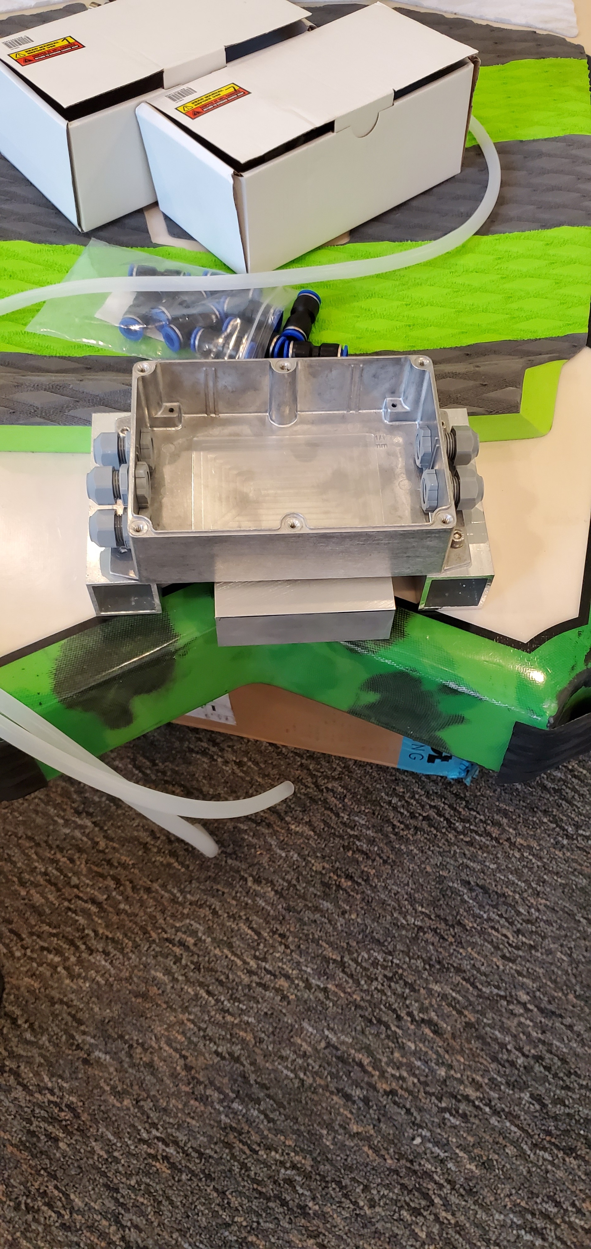
Cable glands installed in battery and VESC box. The aluminum enclosure I am using is from Polycase. The machinist at SCU noticed that it was casted and as a result while cooling it “slumped” slightly (imperceptible to me). As a result he machined the surface around the cable gland holes to be flat to ensure a good seal. I will also add silicone sealant to prevent ingress.
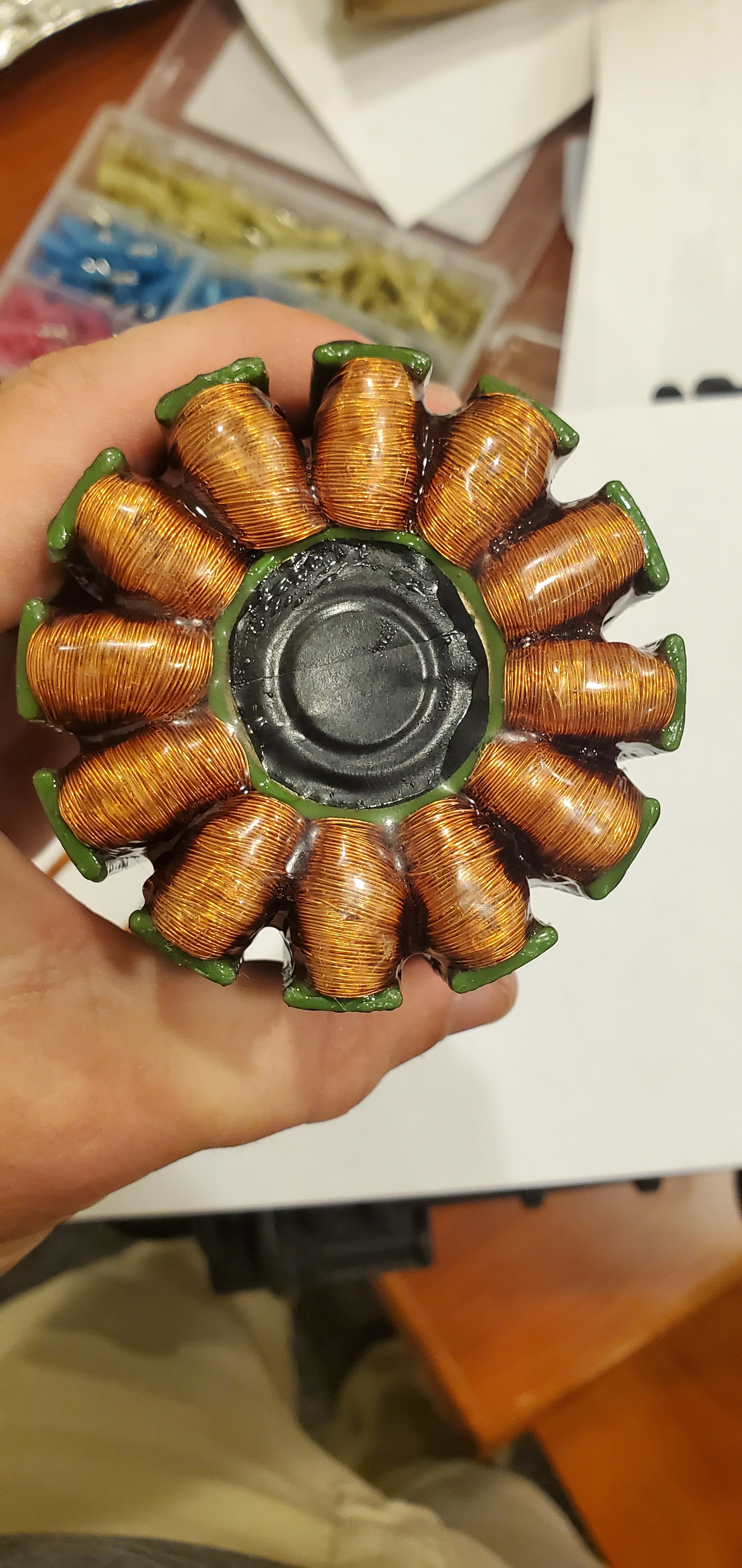
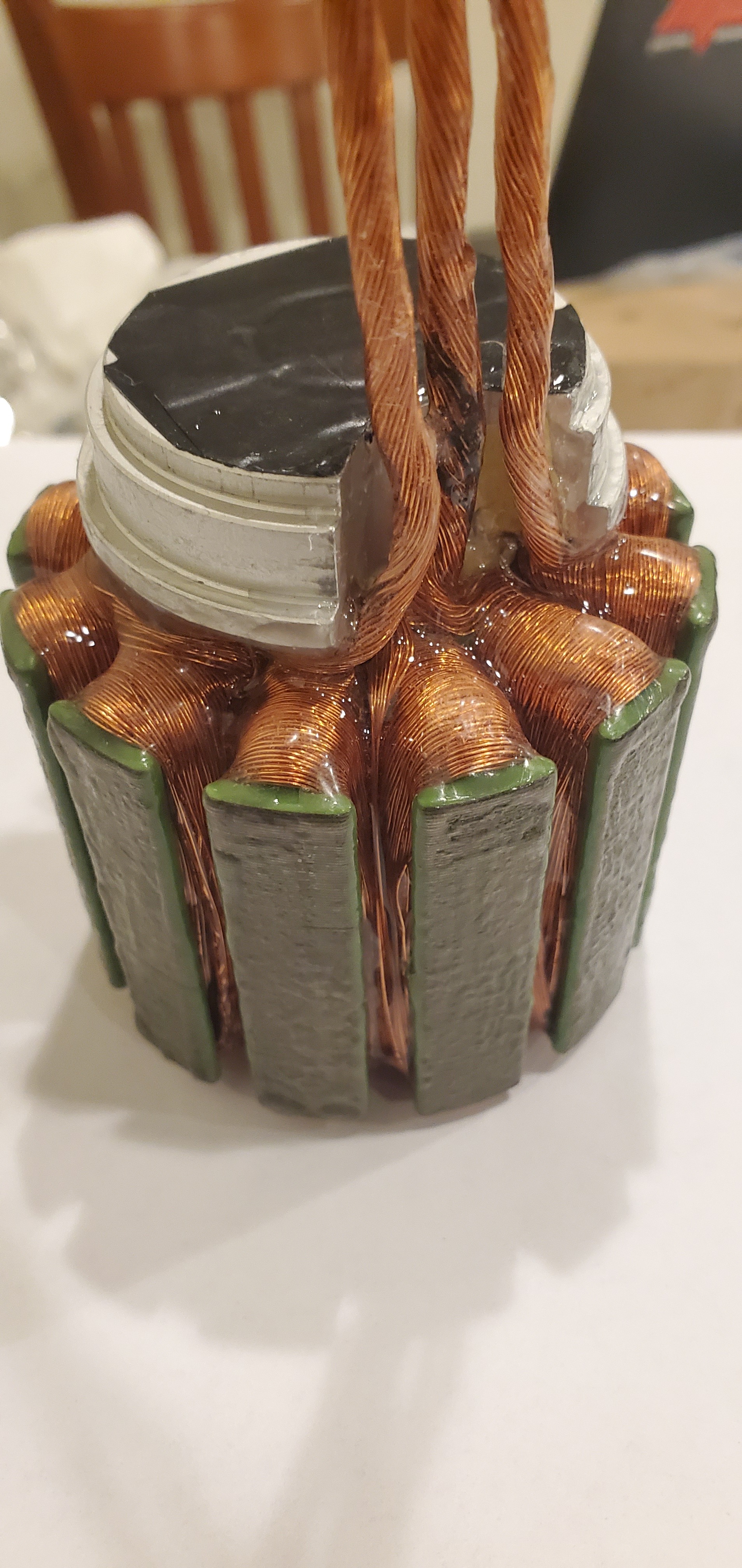
Additional epoxy has been applied to the stator. I would like to do one additional coat to get some missed areas on the top and underneath the green rectangles. I am curious what the purpose of the epoxy is after watching this video where an electric motor worked underwater without epoxy:
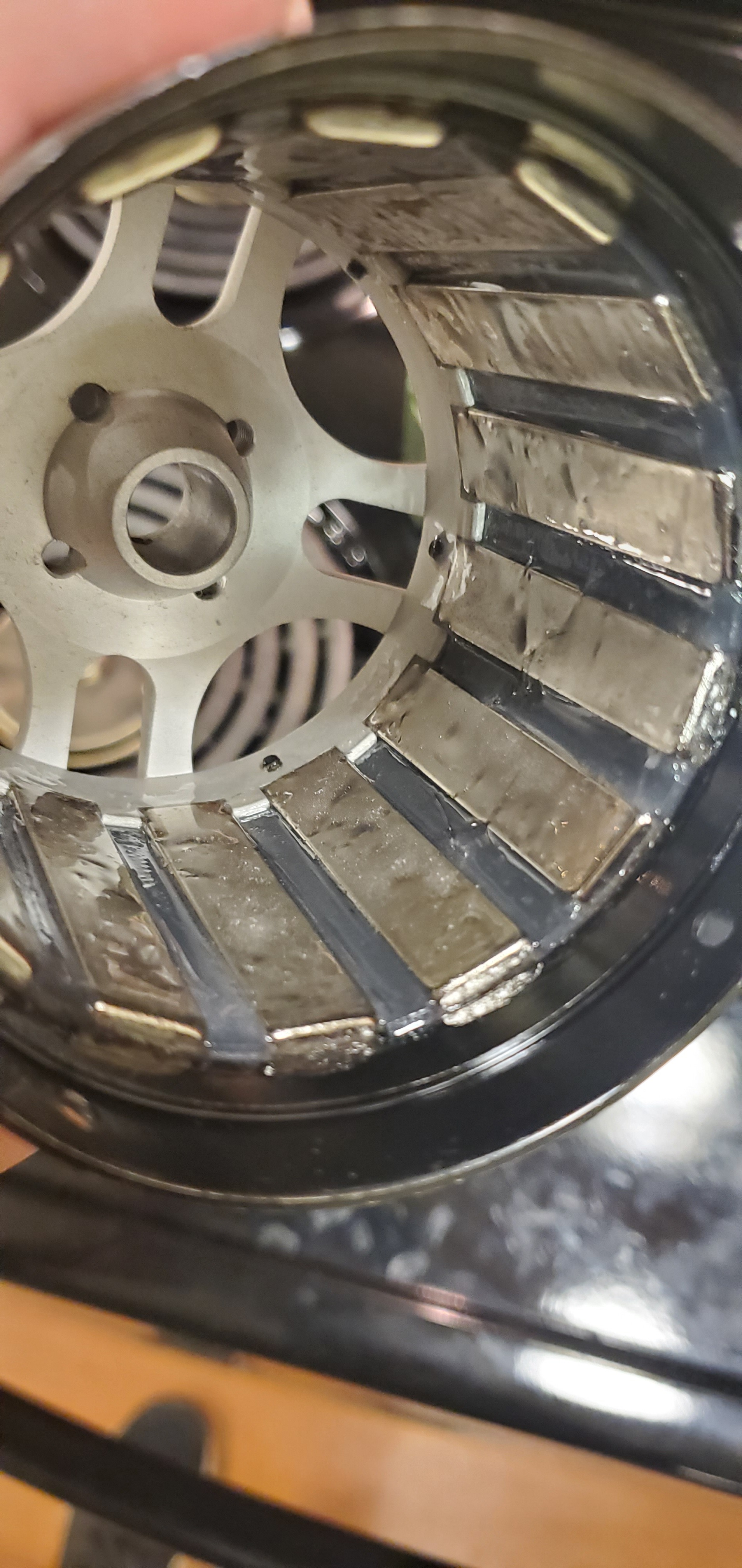
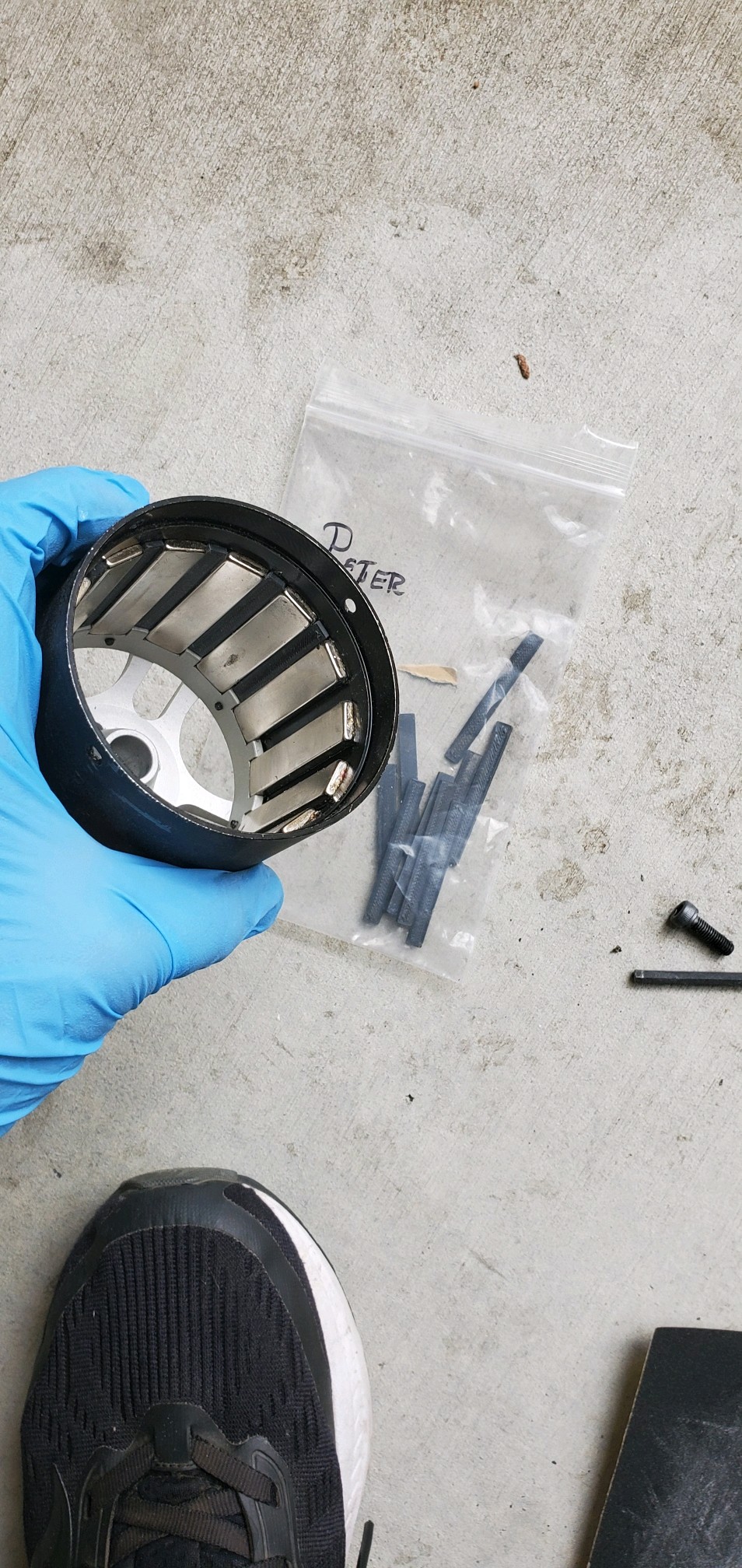
I also applied epoxy over the ASA inserts and magnets inside the can. I will use sandpaper to smooth the inside of the can and outside of the stator in 24 hours. I will reapply to the can if needed.
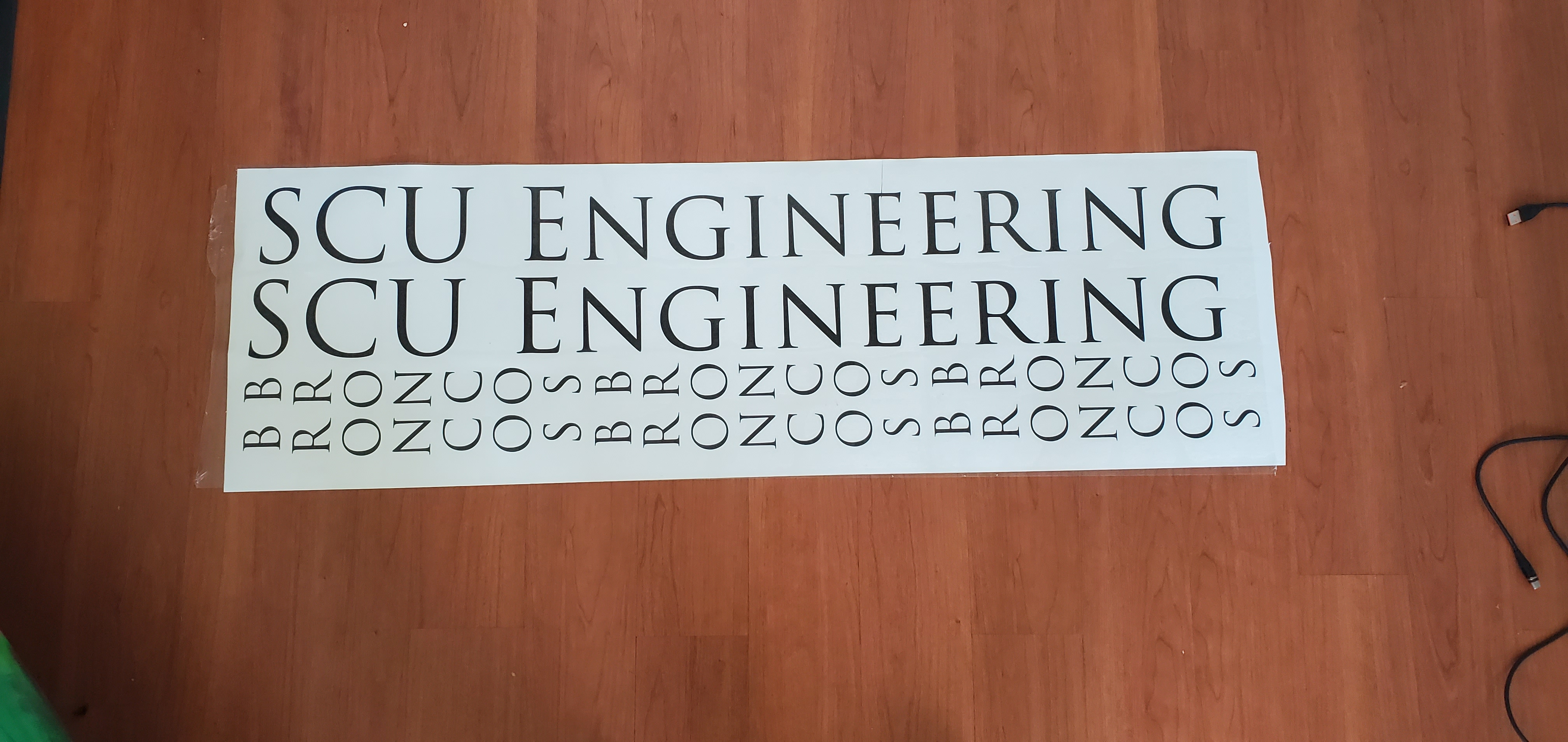
We are switching to the 2020 Slingshot Outwit 7’6" for our board as the Airstrike was unfortunately damaged. I hope to repair it and use it in a future build at a later date. The SCU Maker Lab made vinyl decals. “SCU Engineering” for either side of the board and a vertical “BRONCOS” (our mascot) for either side of the foil mast.
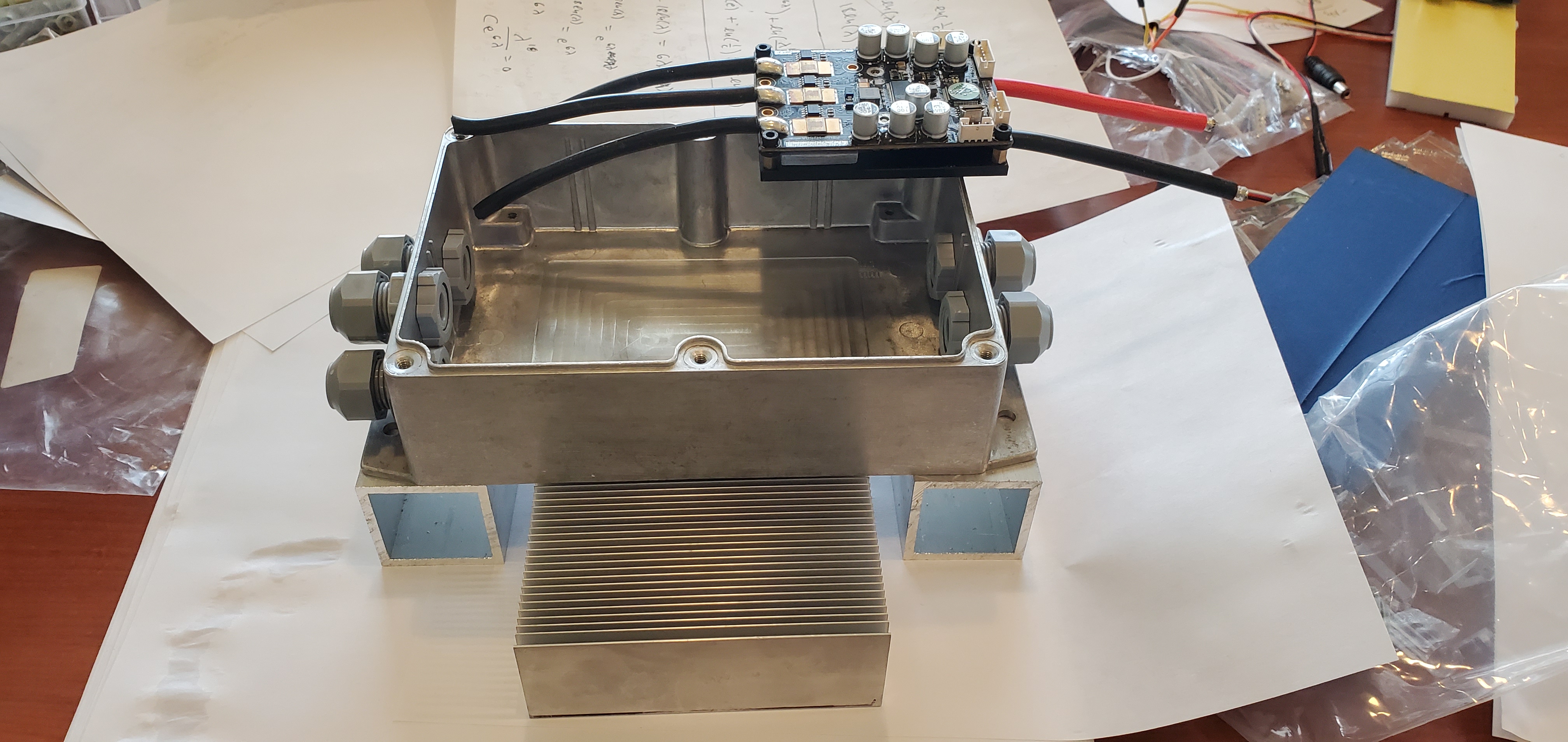
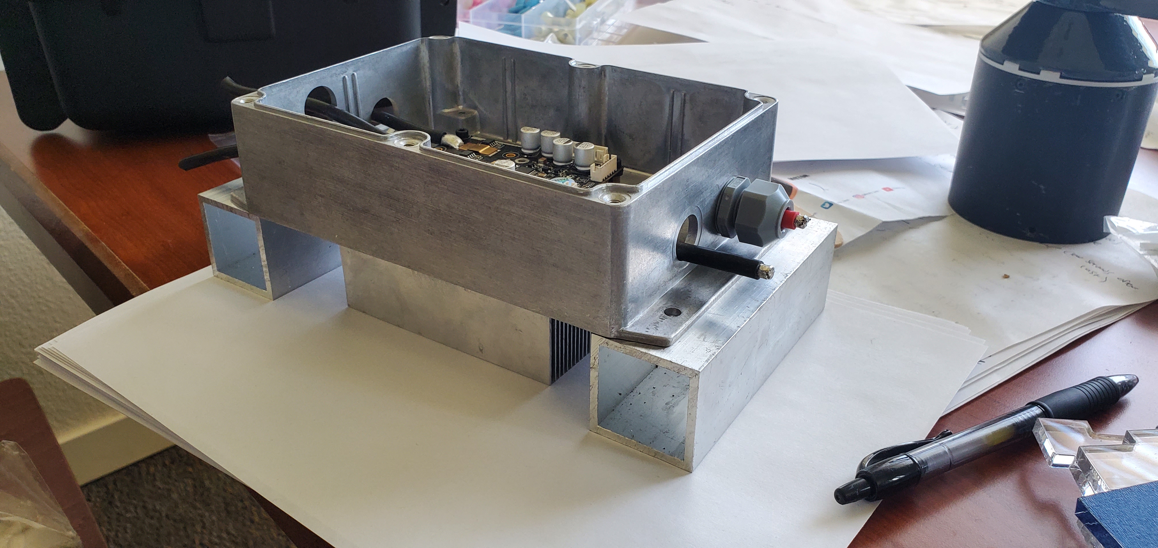
As previously mentioned the timing of this project is very tight. I have less than 10 days to complete the build and record a demo. I cut out the 12V circuit and water pump from the design in favor of a passive heat sink. I’m not satisfied with this setup as mounting it on the Outwit would be difficult. The sharp corners also make me uncomfortable. I am going to ditch the heat sink all together. I will bolt the VESC box to a piece of polycarbonate using the flange. I will bolt the polycarbonate to the Outwit board using the foot strap threaded inserts. I hope the aluminum box acts as a heat sink and the VESC does not overheat.
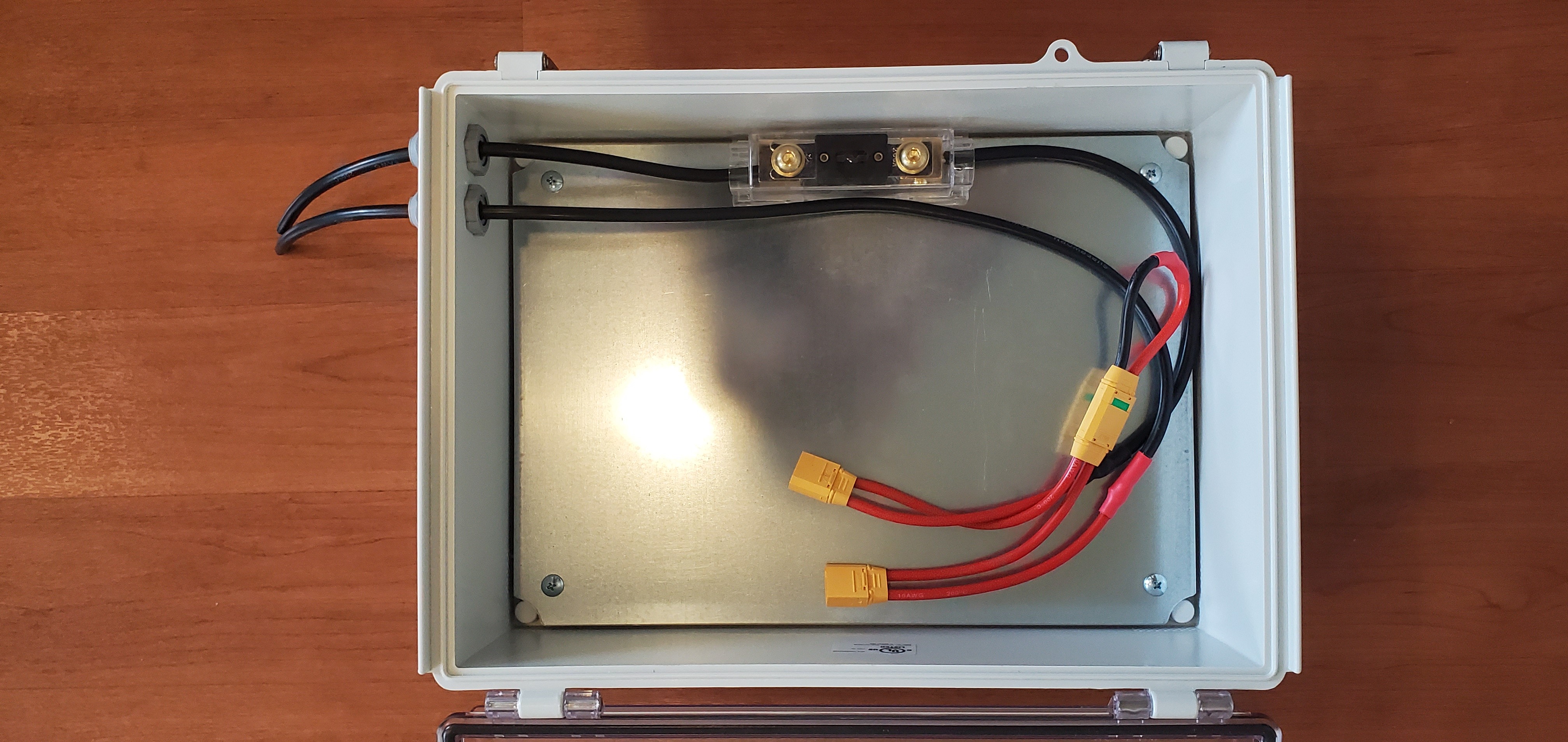
I finished the battery harness! I made a time-lapse which is uploading right now. It took about 3 hours and the time-lapse is 8 minutes. I can connect each Li-Po pack into the harness and it is fused to protect against shorts. The anti-spark loop key is my power switch and is inserted on-site prior to sealing the case and riding.
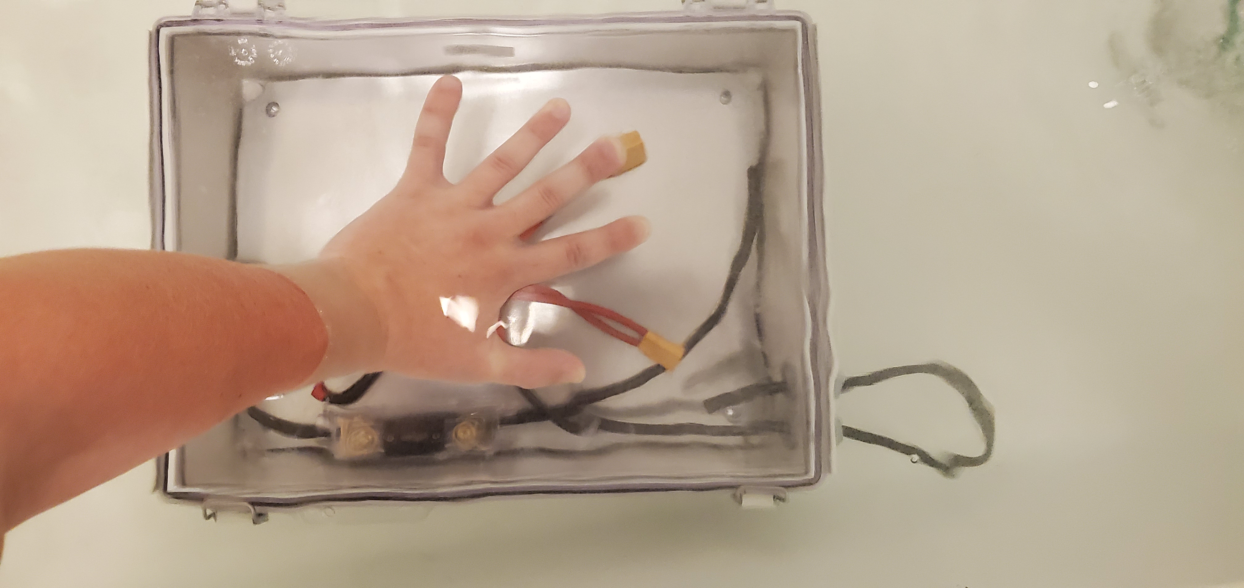
Performed several leak tests in one of the SCU ingress evaluation tanks. I am impressed by the seal provided by Polycase cable glands! No silicon sealant, hand tightened best I could. I will open the case after it has fully dried for an inspection. So far, so good.
interesting use of black and red cable 
1 Like
Haha I was waiting for this! What color are you supposed to use for connecting two packs in series? Black from the negative of the one then splice it into the red of the positive for the next? I said screw it, I want black cables running outside the box. Shrink wrap color denotes polarity on harness. I will shrink wrap a piece of red on the positive cable exiting the box.
Broke the nice finished ASA printed front mast clamp after sanding and epoxy by forcing it onto mast.
Used the PLA prototype to mock the stator wire sizes.
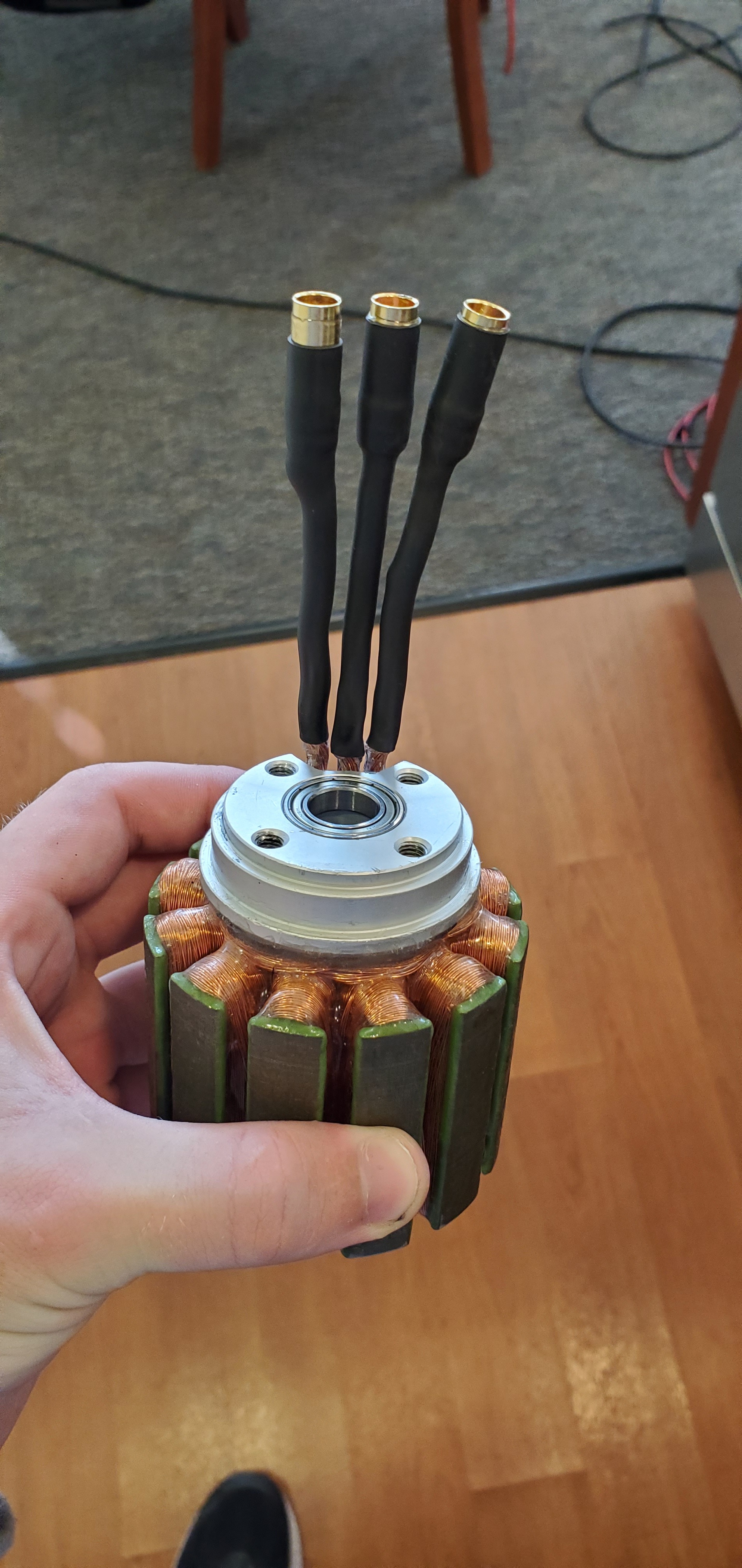
Made the motor wires too long so it’s hard to connect the connectors. A word of advice, don’t stay up all night building your e-foil. You make mistakes.
May I ask where did you get your mast from ?
Also, you should definitely polish the excessive epoxy you put on the magnets and stator. Otherwise you‘ll lose some power there.
Hi thank you for the comment. I sanded the inside of the can and did another coat. The reason the first coat was so sloppy was because my paint brush had a metal handle which kept getting attracted to the magnets slapping epoxy everywhere. I did a light coat with a foam wooden handle brush and it looks good. I will post a picture for you now. The mast is from the “RL kite” optimized foil. I am drilling new holes in the Slingshot 84 fuselage to make it work with it.
1 Like
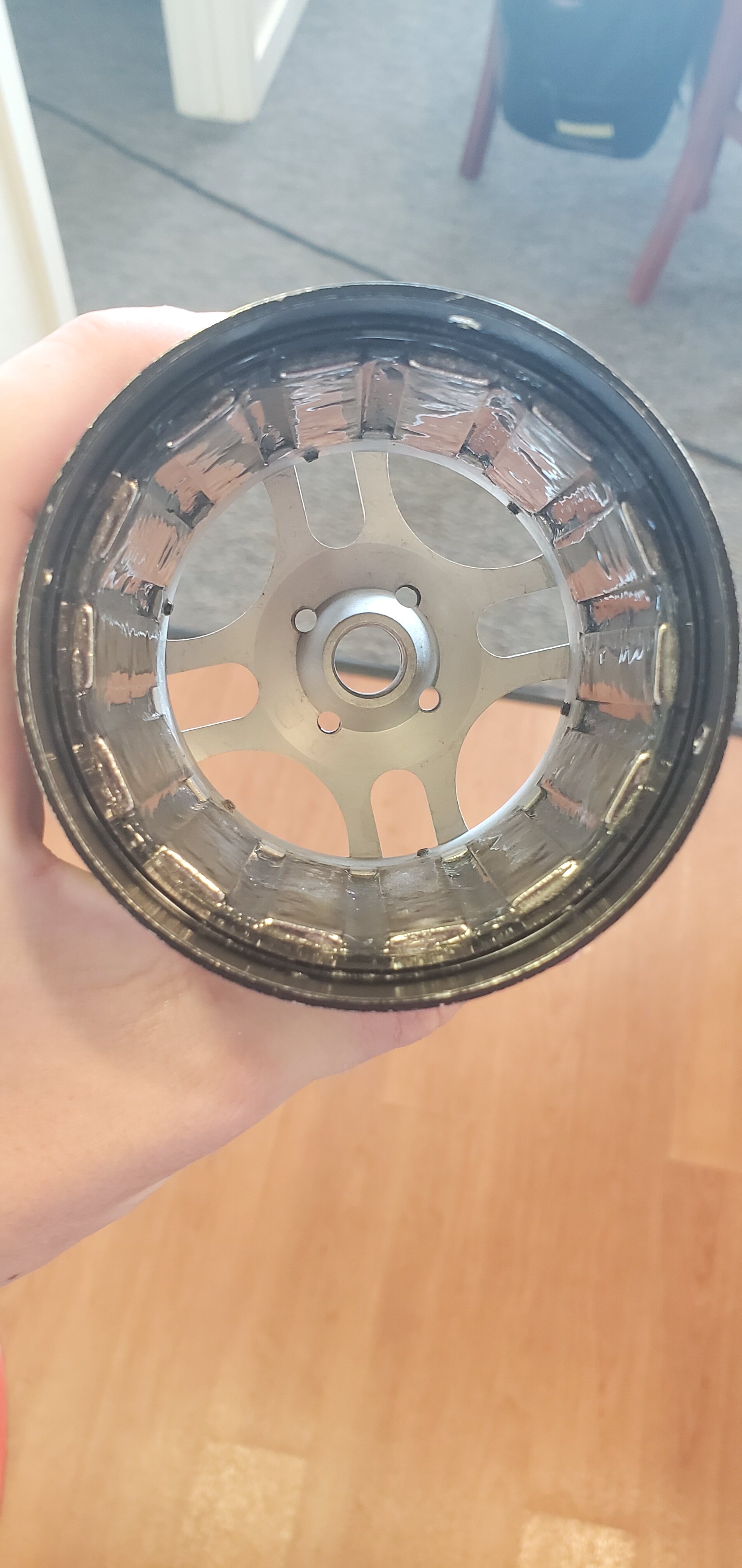
@Sliman_O Here is the final can surface. What do you think?
I also wanted to ask the importance of covering all the windings with epoxy. It seems the magnet wire is insulated as is. I had to shave the insulation off to tin the ends and solder connectors. Is the purpose of the epoxy to protect the windings from damage?
I think there is way to much epoxy on the magnets. Someone posted a while back a video of him (I thik Mat) epoxiying the rotor bell on the lathe. This allows him to have a really thin and omogenous film on the magnets.
Think of it like 2 magnets needing to repel / attract each others. The more materials you have in between the less the attraction / repulsion force is.
Also, we usually speak about less than 1mm air gap between rotor and stator (for a motor of this range, don’t get me wrong), so 0.5mm have a huge incidence on motor performance.
1 Like
Ok I understand what you are saying and I will sand down the magnets. What is the purpose of the epoxy on the windings? Should I sand that down too?
No don’t sand the epoxy on the winding … I guess it will protect the winding from rubbing parts: salt , sand …
1 Like
Purpose is to prevent them to corrode with salt water. It might happen so it’s better to epoxy the stator like you did.
However, by doing this you also put some on the stator slots, which you will also need to sand if there is too much like on the rotor.