Thank you for the input. We are testing in freshwater as I don’t have time to swap the bearings. This is good to know. The stator slots are the green rectangles that effect the outer diameter of the stator correct? Sand those down to ensure outer diameter does not change so can/stator do not connect. Please confirm and I will do this. Thanks again.
I soldered 8awg wire extensions to the 3 phase wires of the VESC. I was not confident enough to remove the 10awg wire directly from transistor and solder on the 8awg there so I spliced it in. I think it should be fine for version 1. I will be adding jumpers from one of the phase wires and the input battery wire to the Maytech remote PCB. I will be able to get voltage/RPM on remote display without hogging the UART port so it can be used with a BT adapter for data-logging to Android phone.
Yes, that’s it.
Also, it has been proven on other threads that those glans do not give you a tight fit resulting in good waterproofing. Try searching the website for cable glands for some more info. I suggest you brass nickel plated glands.
Great I will do that and post pictures when I’m done. Thanks.
Just adding the 20 characters left 
I proved in my test they work just fine. I will add silicone sealant if you think they need it.
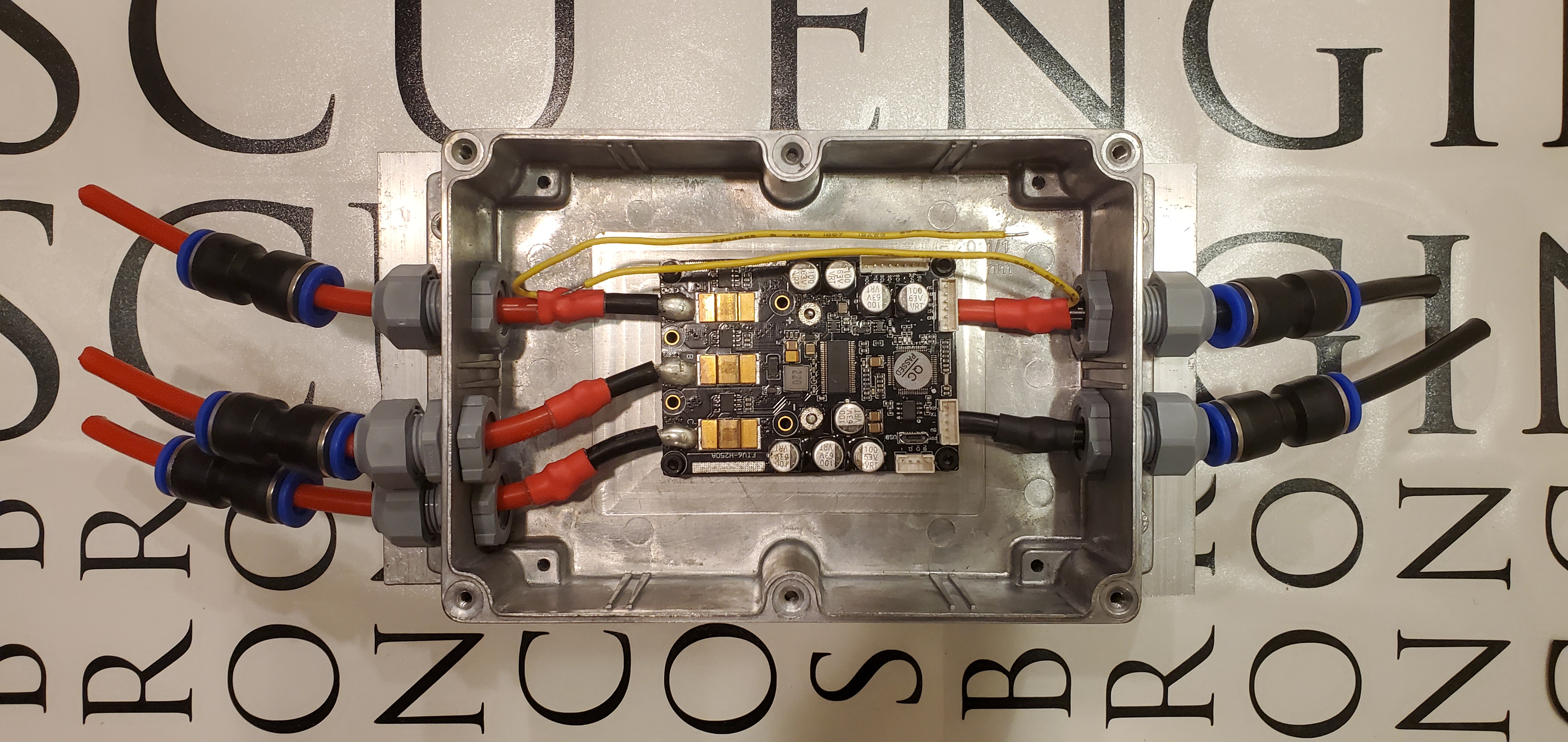
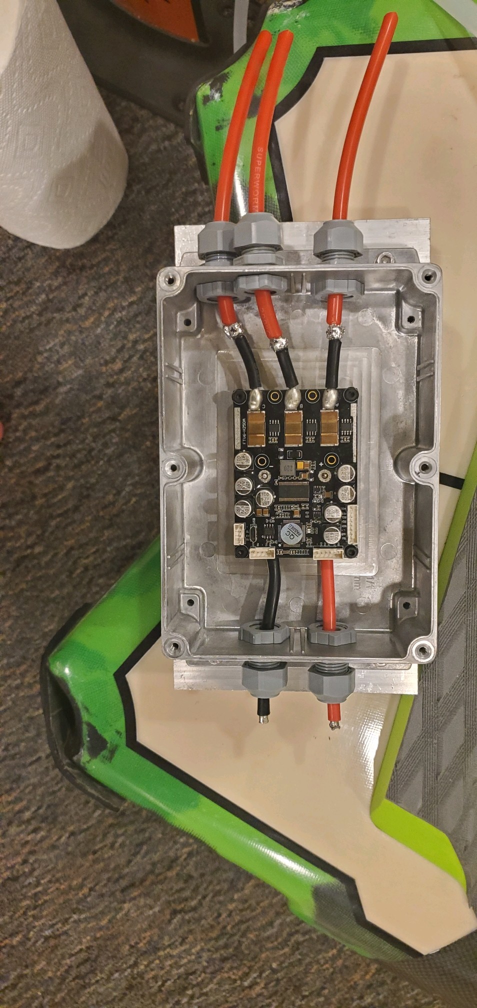
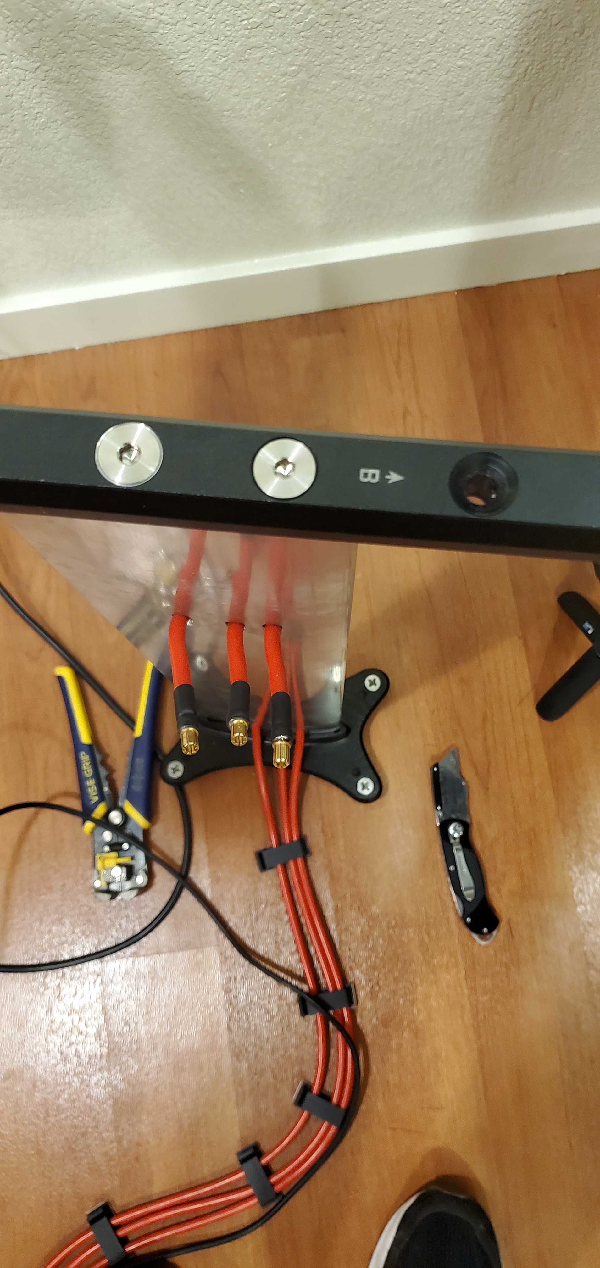
Making progress on motor controller enclosure. I extended the VESC leads and added two yellow jumper wires for the Maytech PCB. I added shrink tube to the exposed solder joints. The pneumatic connectors are on the wires for show at the moment. The next steps on this component are to solder connectors onto each wire and silicone seal silicone tube over the electrical connecters for the pneumatic connectors. Lots of connectors!
Am i correct to assume that those short cables are just for show? Seems like too many joins in there. why is there a cable join 2cm from the ESC on both ends?
The yellow wires are signal wires for the Maytech receiver. The remote can display RPM/voltage either by communicating with the VESC over UART OR connecting these two signal wires. They are not just for show. I did not feel comfortable soldering directly to the VESC. If I fried it I would not be able to demo my project.
Best,
Peter
Understand the yellow cables. How short were the original wires with the ESC? it kinda looks like you cut off a length, then added it back on? (to change color) I’m asking about the 8awg wires after the Pneumatic connections-.
I’m not sure if I fully understand the question but I think you are asking why I cut the VESC wires shorter then extended them. It is for multiple reasons. I wanted to add the jumpers without ever bringing my iron to the board. The other reason is I wanted the cable glands to seal on my 8awg wire (as opposed to the 10awg original leads). The cable glands have to be tightened more for smaller cables. I don’t know this to be true but my intuition believes the glands seal better around larger diameter wire.
there’s some more cable shown exiting the pneumatic connectors which have cut ends, these are shown for demo, or you plan to make more connections to the BATT and ESC? or maybe you just slid those pneumatic up onto the cable?
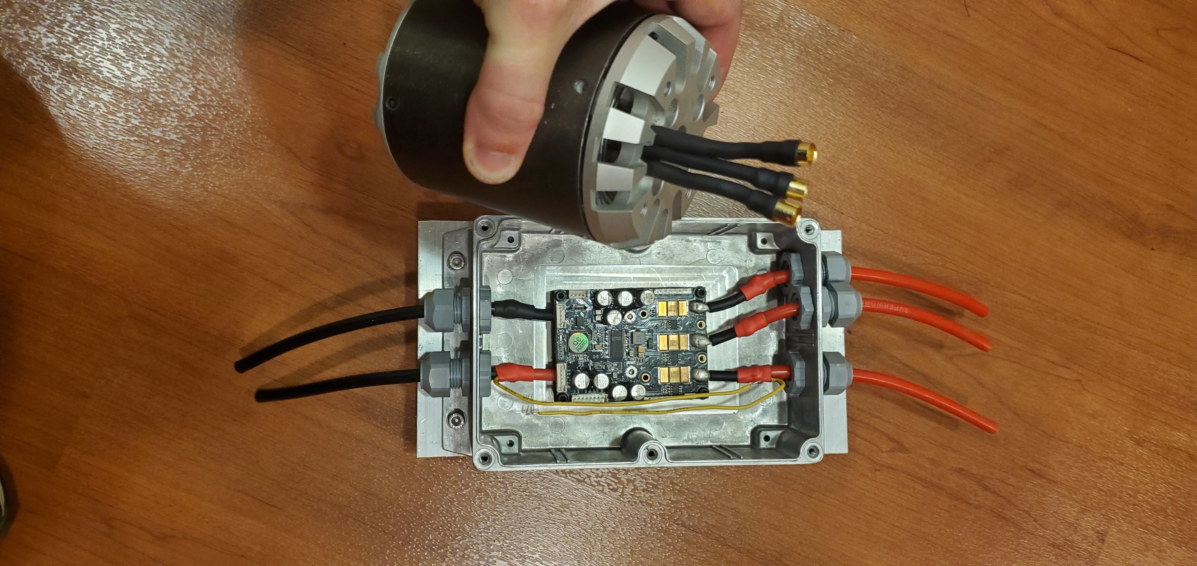
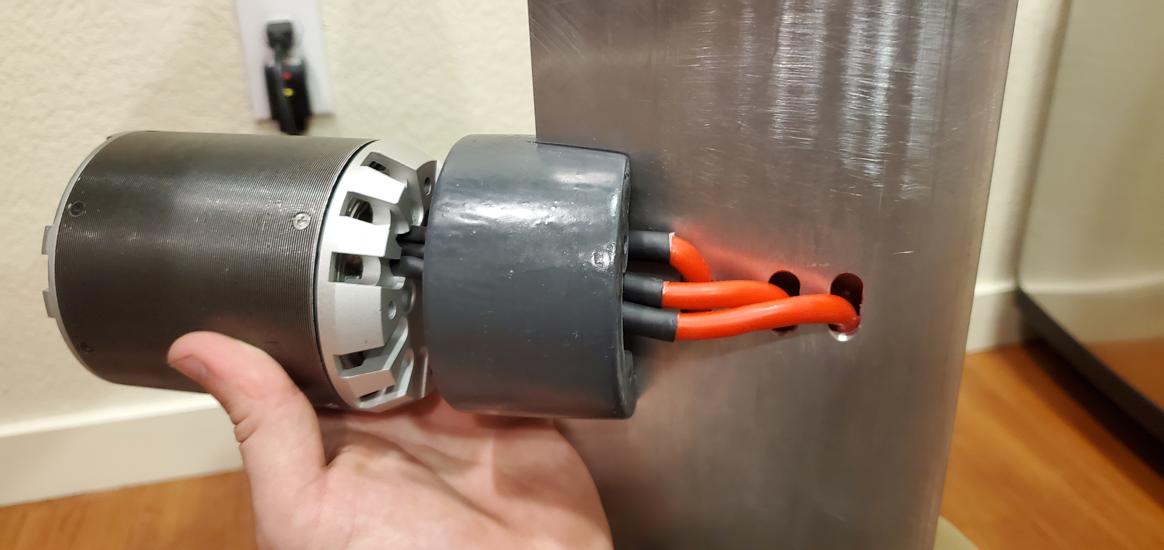
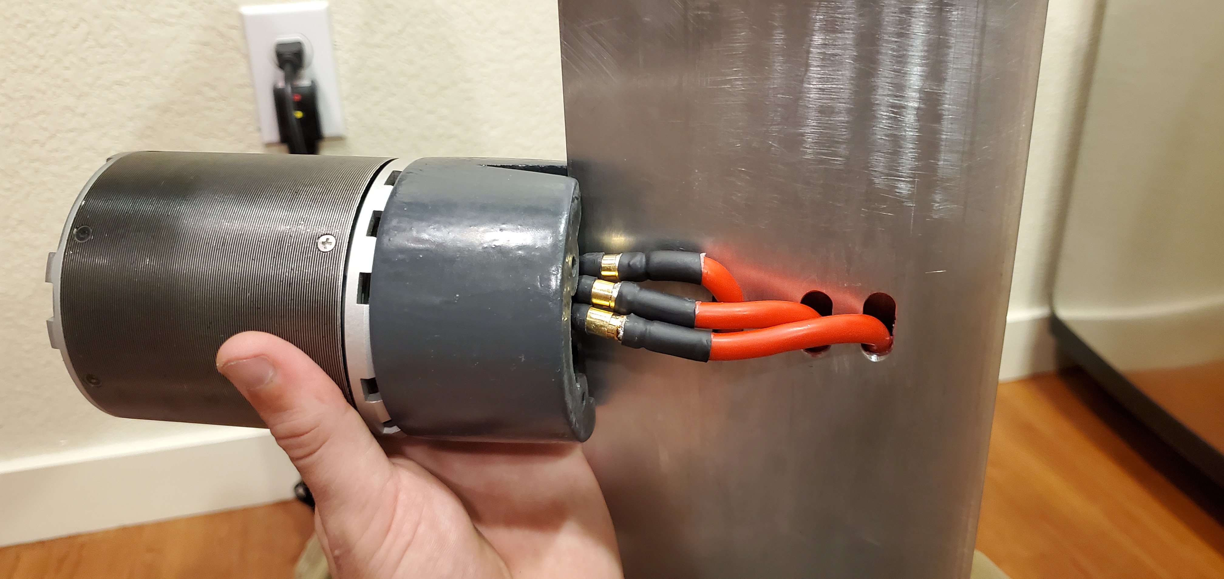
I believe this picture will answer your question. I also wanted to show you the motor wire connectors I have finished. I am working on the cir-clip installation. It is really fighting me.
Aha, more sense for sure. Good work.
1 Like
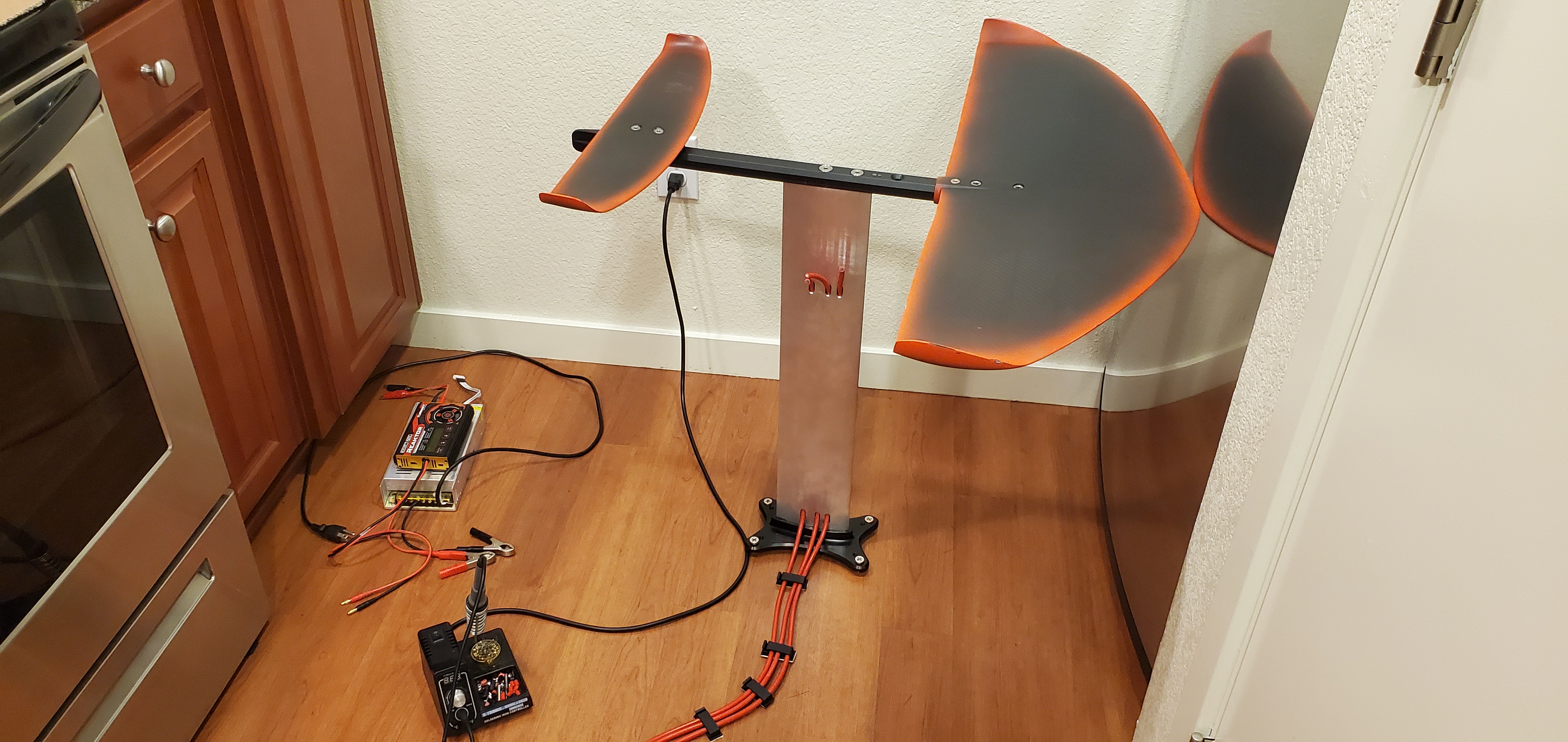
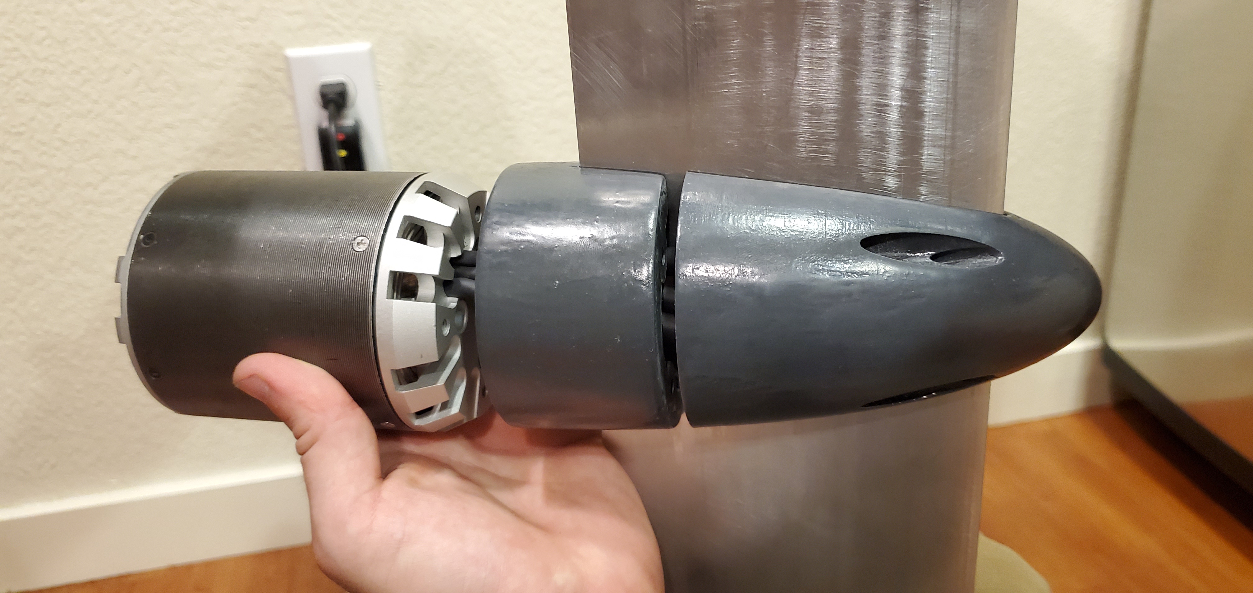
As you can see, the rigid motor wires are too long. It is a huge pain to adjust the length of these. It involves cutting the heat shrink, scraping epoxy, removing magnet wire insulation, tinning the ends and then adding connectors and heat shrink. Time for bed.
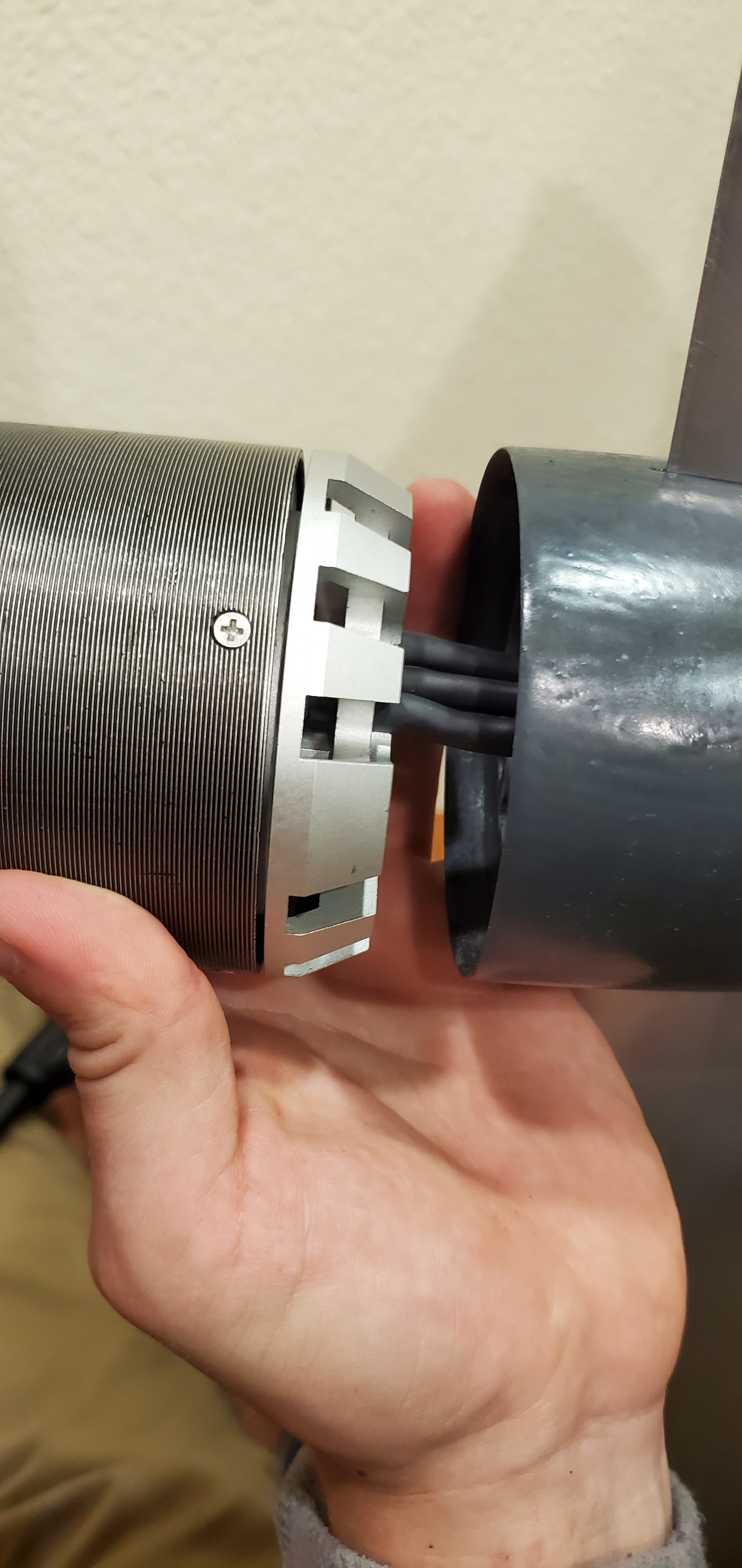
I need to shorten them by this much. At least now I know and am no longer guessing.
The silicone wire continues to impress me with it’s flexibility.
Once this assembly is complete I will finalize it with heat shrink over the connectors. It can always be cut if the motor needs to be removed.
but it is not waterproofe???
Please specify which component you are referring to.
on the last pic, the connectors inside the mastclamps?