So a good friend and college of mine Adrian, has a wealth of electrical knowledge. Naturally, Ive been bending his ear for the last few weeks asking for some help on the electrical setup.
Anti Spark and kill switch being important. Adrian pointed out that relays for 100+ amps are big, and in extreme cases can fail. He suggested solid state relays (mofsets) and offered to draw up a circuit board design to incorporate 12v (for pump) 5v for receiver, PIC chip for pump control, Anti Spark and kill switch.
Adding a passive AMP meter onto the board and using VESC protocol to send Battery AMP and voltage to compatible receivers (Maytech V2) for non VESC like the seal 300A
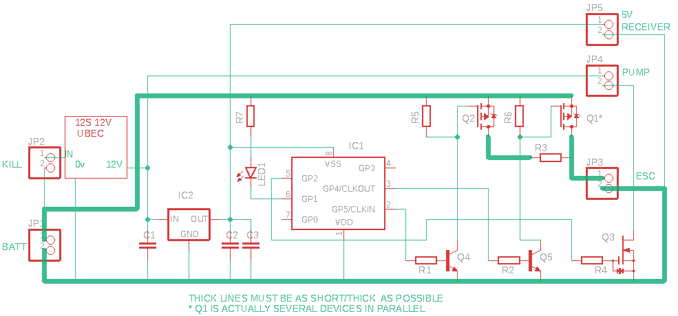
Below is the logical layout.
Q1 is 6 x IRF4905
Q3 will be an IRL2203N
116Amp transistor to run a 0.3A pump
Q4/5 will be 2N3904
PIC sets the anti Spark timing for the smaller mofset Q2
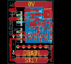
Here is the PCB design

The idea is if the kill switch (manual boat/jet ski style) is off, everything is safely quickly disconnected.
Using just one 12V UBEC, the board offers connection to receiver and a 12v pump.
Ild like your feedback and let me know if i have missed anything vital, any glaring mistakes or feedback appreciated before i make a 400 euro smoke bomb.
