Custom Motor Build (not made in china)

Hello all,

My friends call me Kipper. For over a year now I have been reading these forums on building. I have learned a lot and have taken many notes. About six months ago I started something I personally love to do, create a parts list for a project and long story short, I was not satisfied with the motor options available. The one I wanted was out of my price range, and all other cheaper options did not compare. Now I had dealt with Chinese manufactures before in my other online business. For this business I have custom components machined in china to my drawings (I have a mechanical engineering background). I watched many posts die and fail about “custom motors specifically for hydrofoils” on this site but I was sure I could do better. I did not. No manufacturers I found could give me new information on motors, or seem to be able to control how they were made.

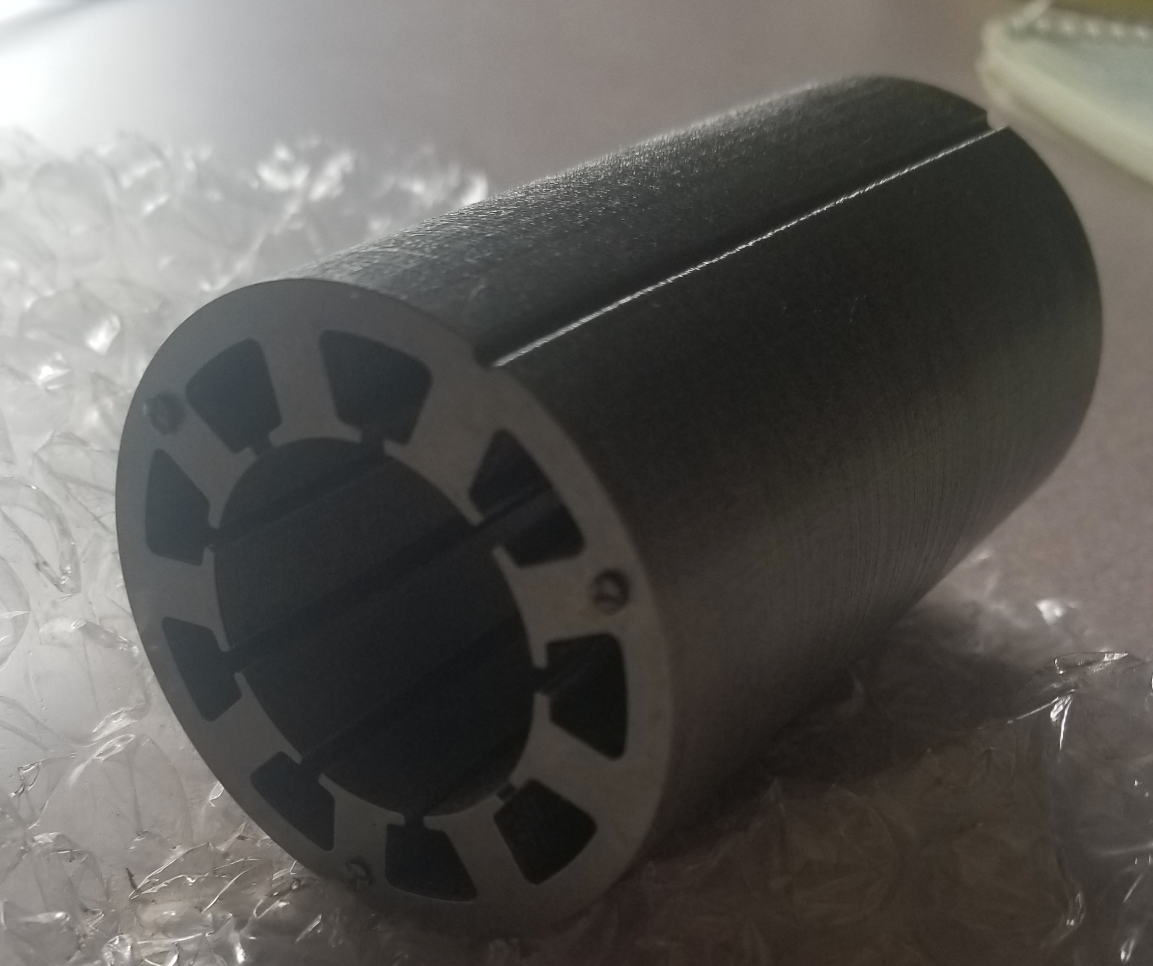
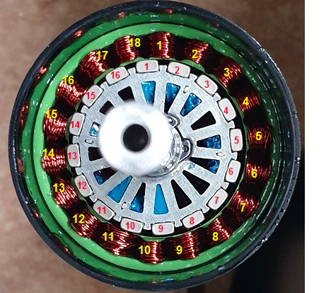
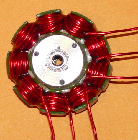
So it was back to the drawing board. Crazy idea, I’ll just build the motors myself. And that’s where I am today. So I make no promises because I have done no real world testing or have every built a motor before. But I have easily spent well over a thousand hours researching brushless DC motor theory, construction, material specifications, magnets, magnet wire, and the list could go on forever. I have completed magnetic motor software simulations on my design and feel confident in the results. This software provides me with the motor losses in watts, torque, and other data based on my given stator, rotor, and magnet geometry plus number of windings and direction. I have settled on a 9 stator 8 magnet design.

The obsession with building an electric hydrofoil and flying is still with me despite this bump I created in the road for myself. And this may seem like a round about way to get there. But from my perspective I am young, ambitious, I have an entrepreneurial spirit, I have a love for water sports, and I like the idea of making this sport a hobby as well as a career. If I can sell something cheaper and better than everyone else I am going to do it. And it is looking so far that dream is feasible. This is what has led me down this side path of building my efoil. I saw a market, and I am going to attempt to take it.

I have already had sample rotors and stators delivered to my house, have a copper polyamide magnet wire sample pack on hand to try different windings, and my custom N45SH magnets are on order and should be here by the end of the month. I understand there is probably going to be a lot of headaches I do not foresee coming down the road. However I feel ready for these challenges.

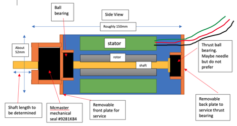
Now, this is the point where my lack of real world knowledge hurts me and I am asking for everyone’s help. I am currently designing and looking to have made shortly the actual motor housing. This requires bearing and seal selection. Who better to ask then the people who have some efoils on what works and what doesn’t? Also what is the preferred shaft length and diameter to attach propellers to? I know these questions have been asked before. But this is a little different we can dream up anything we want together.

Let me know what you think.

Thanks!

-Kipper

image

2 Likes

Can we have some pics ? Before assembling

This motor size would be enough for Efoil ? 52x110

It have not enough torque!
It’s too small, more Diameters must have.
Greetings Frank

Alexandre, as far as pictures go. I do not have anything too impressive. But I do have the magnet wire and stator and rotor. The stator and rotor in my opinion are the hardest to source. It still needs to be insulated and coated before coils.

Also thank you for your concerns Frank. Do you have any numbers that somehow shows the relationship between motor diameter, length, and torque? Cause I could not find anything in my design process. The motor torque and efficiency are based off motor length, diameter, coils to magnet ratio, coil wire diameter, copper fill of the wire, and magnet strength, among others. So by optimizing each of these components the idea is to minimize losses and create a more efficient and smaller motor than the flipskys of the world.

There are limitations as you suggest. But based off my numbers and control of the components going into each motor, I am pretty sure it will work. Or at least this will get me really close and the second prototype will be better as a result of the first.

3 Likes

Taken from:

The MIT lecture references are there too.
But in short:
.

So how does
T = 4 * m * N * B * L * R * i , otherwise known as T = Km * i
affect your motor design, and why am I viciously pounding on torque so much? Because torque is ultimately what hauls you around, and is one of the components of mechanical power Pm . Once you determine roughly how much mechanical power you will need, you can size wires and components appropriately.
Notice some key characteristics of the equation and how they affect motor performance:
ďż˝ Torque increases with number of turns N
� …and radius of the stator R
� …and strength of the magnetic field B
� … and length of the stator L
� …and winding current i .
What we observe here is that to a degree, you can linear scale motor characteristics to estimate the performance of another motor.

If you are only interested in the T ~ [R] then your N has also a relation of N ~ R, because with a bigger radius you can fit more turns in now bigger slots (assuming you keep the current, hence the wire thickness). Maybe even something between N ~ R and N ~ R² when you also scale the slot depth with the radius.
So in general:
T ~ L
and at least T ~ R² .

2 Likes

N : doesn’t give the « kv » as well ?

Lower kv , finer wire, more N possible and needed?

I think the mean problem is that you need low kv and only 14s max possible … so big motor …

http://www.bavaria-direct.co.za/constants/

Sure, as well as every other parameter changes the KV. Because Km ~ 1/KV.

But then you change the current capability. Thats what they do with the SSS motors. Every SSS 56114 has ~45kRPM and max “rated” 13kW.
So a 350KV SSS 56114 is up to 130V and 100A (N=10 thin wire, Y config)
A 1000KV SSS 56114 is up to 45V and 290A (N=6 thick wire, D config).

Problem is weight. Torque is proportional to weight.
All high power density motors have really low torque and high RPM. For high torque you always sacrifice power density, hence weight.
Hub motors are the best example and even Tesla rather uses a fixed gearing than a low RPM/high torque motor.

Giga,

That is a very good instructable, I have gone over it many times. And also as you pointed out, all the parameters change the KV. So basically I have set the rotor, magnets, air gap, and rotor right now. The plan is to wind a phase and count the number of turns, check the KV using a drill motor test. From there I can use the proportion Test_KV/Test_winds = Target_KV/Target_winds. I can solve for how many winds I want. After that it is up to the capability of your winding mechanism to wind a motor with the largest diameter wire at the desired turns to try and “fill” as much of the stator as possible with a goal of minimizing air gaps. There are many white papers written on this. But the best source is in these forums in my opinion:

https://www.rcgroups.com/forums/showthread.php?240993-(Re)winding-and-building-motors-tips-tricks-checks-tests

Okay so for an example. Let’s look at the FR.

image

Now these winds are pretty good. But someone correct me if I am wrong, but this looks machine wound to me. And maybe wires wound in parallel? Maybe not. It’s a common practice and there is nothing wrong with it. But lets compare it to some of the hand wound german work from the early 2000s. Keep in mind this is an inrunner versus an outrunner. But you get the point.

http://www.modellflug-hager.de/

image

This is the idea behind the custom not made in china motor. So looks let look at some numbers about increasing motor efficiency. Directly copy and pasted from the RCgroups link above.

"
Say the motor has an efficiency η = 0.700 and it can handle 500watt input. That means it can get rid off (1 - 0.7 ) × 500watt = 150watt excess heat. Now, by cramming in thicker wire (and/or using better stator-iron, segmented magnets), efficiency increases to 0.75. The motor’s ability to loose those 150watt has not changed (by radiation, convection and conduction). This means the motor now can handle 600watt before it hits the 150watt (0.25 × 600watt) losses mark.

So, going from 70 to 75% efficiency gives an increase in power of 20%, factor 1.2. That’s why efficiency plays such an important role, in any motor design: efficiency governs maximum power. The motors weight may have increased a bit due to more copper. All of this assuming the iron will not saturate magnetically.

A rather extreme example, just for calculation’s sake/fun: going from 80% to 90% efficiency would increase the input power the motor can handle by a factor two (a.k.a. 2) Going from 90 to 95% efficiency would increase power again by factor 2
"
This is my general defense for my current chose motor design. And also since rotors and stators are stacked laminations, it is easy to order them at any length. The same is true for the magnets. Which is another way to increase torque.

After the KV is correct and the motor is wound to specs the only option from there would be to test to figure out if it has enough torque without burning. At least I think that would be the best way to test it. But to test I need to be able to submerge the motor with a propeller on it. Which was the reason for my original post about the best seals to use. I am not trying to be sassy just explaining my plans and current ideas on the build process for you all. I appreciate the discussion and scrutiny, I would only do the same in your position. I can just order the seals I think I need in the mean time and post pictures. I know how to get your opinion.

And about motor without stator ? I believe Lehner are made like that

I am not sure I understand the question. Could you clarify?

Some manufacturers don’t use the iron support to make the stator , just the winding , the motor is spinning freely by hand

So I believe what you are asking is if a no-iron stators and all copper would be even better? From a quick google search they appear to be the next best thing. But once you click down through the pages and read some white papers they point out disadvantages as well. Without a lot of research or some real world experience it would be tough to know all of the pros and cons of the all copper/no-iron stators. There is a lot of research behind my chosen motor design and it is the most popular so I am satisfied with it.

The ironless motors lose torque density and this is what we need… minimal cross section for drag and maximum torque for a slower, larger, more efficient prop.