If you take a closer look, each cell is connected with a part acting as a fuse wire. Which leads me to think, not only they are protecting each cell individually but also certainly the bms.
That’s a pretty nice battery we have there !
Also, what’s your opinion on the bonding method they used on top and bottom part ? Would you say it’s glued or kind of melted together ?
300A for the fuse because they work with heat ( amp) vs time , so over rating will assure life operating
It is all in data sheet
Just like over rating a bit bms , fuses cells …
I used a 200A which go pretty warm with 140A continious
LOL. I wish I did that last top cut a little more carefully like the first 3 now. Very glad to hear this sucker will fit in my board. I am going to try to save the case. The compartment will be 85mm deep, right? I think all my cuts were clean enough that I can pretty easily seal it up with some 3M windo-weld urethane after I decide how I want to rewire for future charging/discharging. I am going to start shopping for a new BMS, but I may just solder up new balance leads and figure out a want to pass them through in a water proof way. I don’t think these little ribbon cables are going to work for me.
I posted that shot of the edge where I cut through. I am pretty certain it was fused together with heat. It really wanted to melt and fuse back together when the saw blades got too hot.
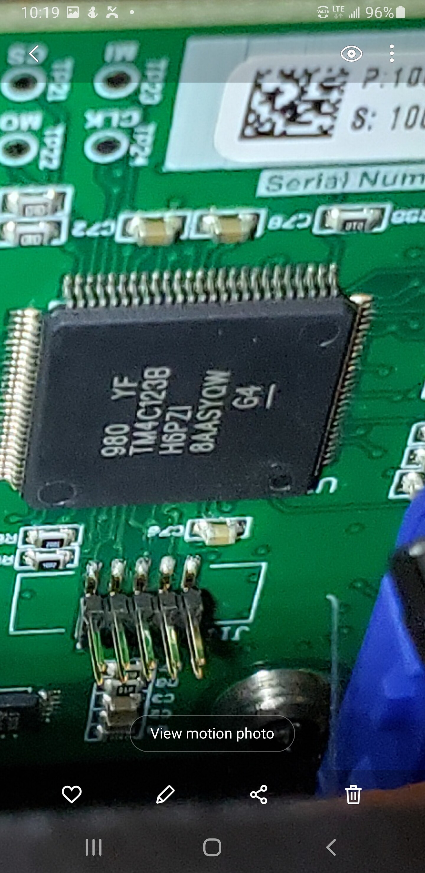
Yes, it is Stafl for sure. Hard for my old eyes to read in the dark garage. I am reading up on their stuff, looks like it would be minimum of 700 + 280 to go the 12s route with these guys. If I am reading it right, their off the shelf system would actually require two monitor units for 14s. We are talking well over 1k for this BMS.
The more I look at the more I am impressed. It gives me a lot more respect for what Lift put together and their justified price point. Before opening this up, I thought $3,500 was pretty hard to justify for an unserviceable case with 196 cells in it.
Any CAN 2.0B experts in here? I will wait to hear if anyone has any advice on diagnostics with the BMS before I unhook much else.
they are using contactor instead of mosfets which has its own pro’s and cons. Contactors tends to wear out and melt and short over time but thermal management is easier.Fets instead have longer life span and much better protection against inductive loads and current inrush. The amount of the cables going around in the box is crazy! Coming with years of background in EV battery industry this is super labor intensive product. Plus not sure what is the material of the box but in these power ranges, without proper heatsinking cells, to at least the enclosure means cells are either always run at the border of maximum temperature or they just let them overheat in expense of reduced life time of the pack
@samisin Would love to hear more of your thoughts on this board. I will pull those numbers and get more pics when I can. It looks too fancy for me to even want to try to spend the time to get it working without the lift esc or charger. I gave it a quick look, but didn’t see any obvious burned/melted components. It seems this BMS system does monitor the battery temps on each series, so perhaps that was part of their plan. Everything else is so well done I would be shocked if they didn’t think of the cells overheating in the sealed enclosure.
Did you test the fuse with multi meter? can you measure the whole pack voltage before the fuse and each packs in series? wondering if the cells are balanced properly. I could be number of continuity issues, thermistor wires, balance leads …
I have a lift battery that has 48v standing at the power inlet. So it is backfeeding Charger and blk box. I was told that it’s a sylonide that is stuck closed. Any idea what sylonide or part?? Thanks
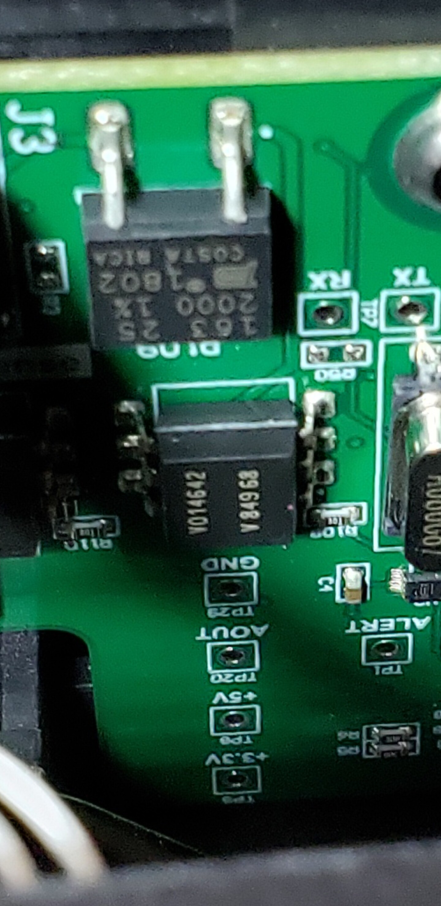
That is the exact problem I mentioned above! the contactor’s contacts wears out over time and conductivity of the contacts degrades and creates more hit and eventually melts and stays closed over time. For high performance low voltage packs I never recommend contactor. I hope they have pre discharge circuit to charge inductance of the load (motor in and ESC our case ) before turning on the contactor. you can easily test it after opening it and replace it. It is the cylindrical part behind the fuse in the picture
I can take some more pics of how it is mounted in a few days so you can see exactly what section of the case to cut open. It is about 100 times more difficult to cut through the seam than just above or in the top. It is going to be very easy to hit a wire cutting in this area as I did. (The orange one to the contactor)
The 7 - 2p14s parallel groups are all balanced within .005 of each other. I need to get to the sides and bottom to be able to individually measure all 14 parallel groups individually.
The fuse is fine. I am going to have to cut more of the case to be able to test and remove the TE contactor. When I use this battery in my efoil, if the contactor is worth reusing, I will be moving it to the exterior of this sealed case. In the data sheets it says it is hermetically sealed and it is also a likely point of failure.
I mangled more wires than I thought cutting across the top like that. For those following me, DO NOT take the shortcut where I did across the top of the case if you intend to continue using the Stafl Systems BMS or contactor. I can draw up a diagram of the safest places to cut if someone is interested and it is not obvious from the pictures. It turns out there are no wires around the handle afterall.
This BMS is really complex. I don’t think there is any way I can reasonably reuse it. The little blue thing in the pictures over the main positive lead is a clamp meter. The ribbon cables appear to be setup in a matrix to measure the voltage of every single cell. The pack is epoxied to the top and bottom of the case. I am dissecting further today. I have to find out if I can get to the sides and bottom of the pack without cutting more of the case so that I can decide how to go about adding new sense wires and if I want to seal a different BMS inside for balance charging and bluetooth monitoring in the future. If I use a BMS at all, I will 99% likely bypass it for discharging.
I am getting braver now that I can see what I am doing and moved the operation indoors. Wish me luck with the next phase of the excavation! More pictures coming.
 .
.
 . Thanks !