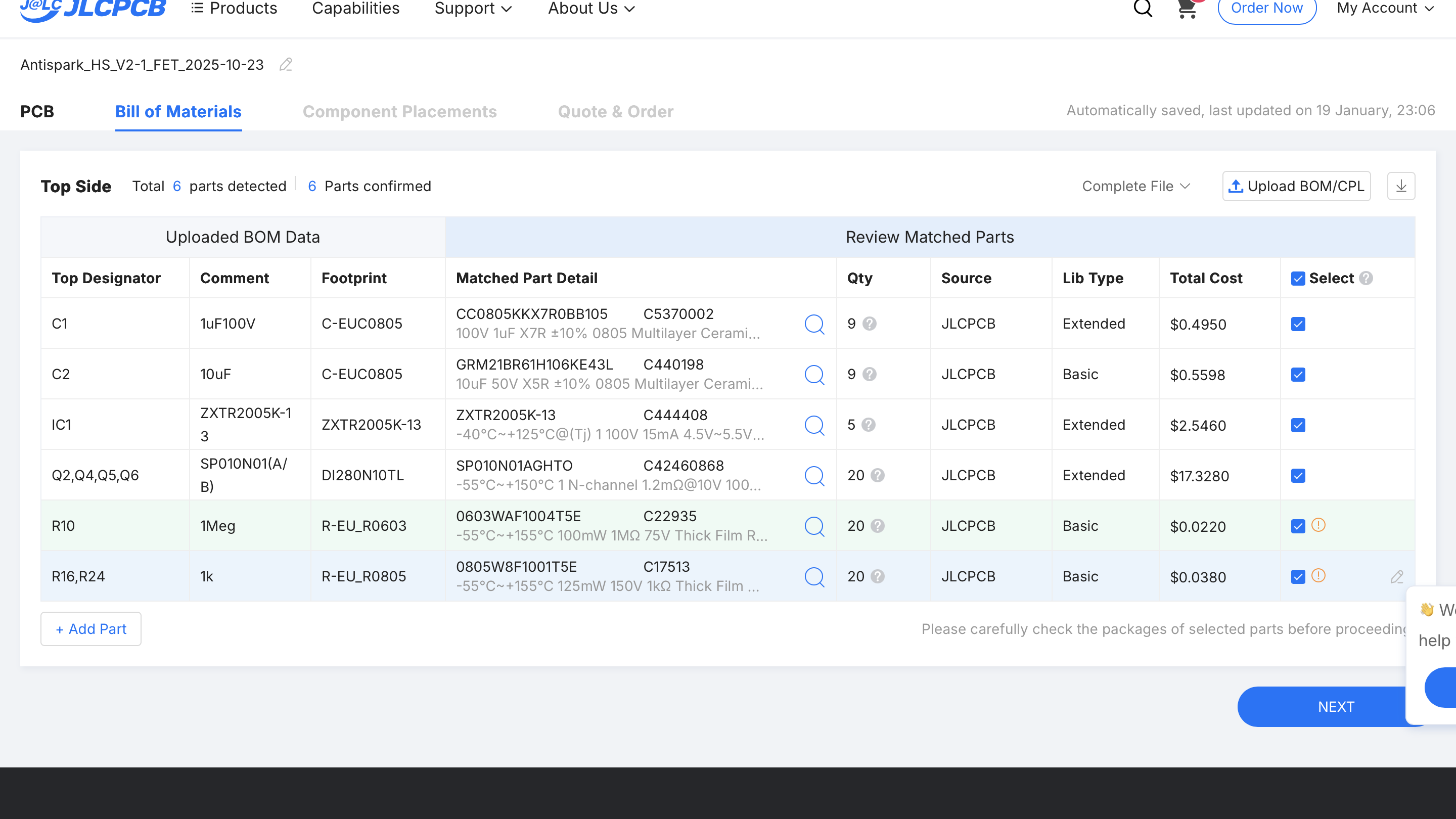
Hey i am also shopping for them and manually replaced the 47R just like you did.
Would you be able to tell from pictures if i did everything correctly? Thanks for helping, i will test different reed switches.
Hey i am also shopping for them and manually replaced the 47R just like you did.
Would you be able to tell from pictures if i did everything correctly? Thanks for helping, i will test different reed switches.
From what I chan see on the images looks good
Yeah, it looks OK. only 47R needed some attention. All the remaining components needed only approval by ticking checkbox
Thanks to both!
@ludwig_bre I guess you separated FET and Logic because of heat transmission? Or interference?
Surely All-on-one board looks nicer and is more easily integrated into lets say aluminium enclosure.
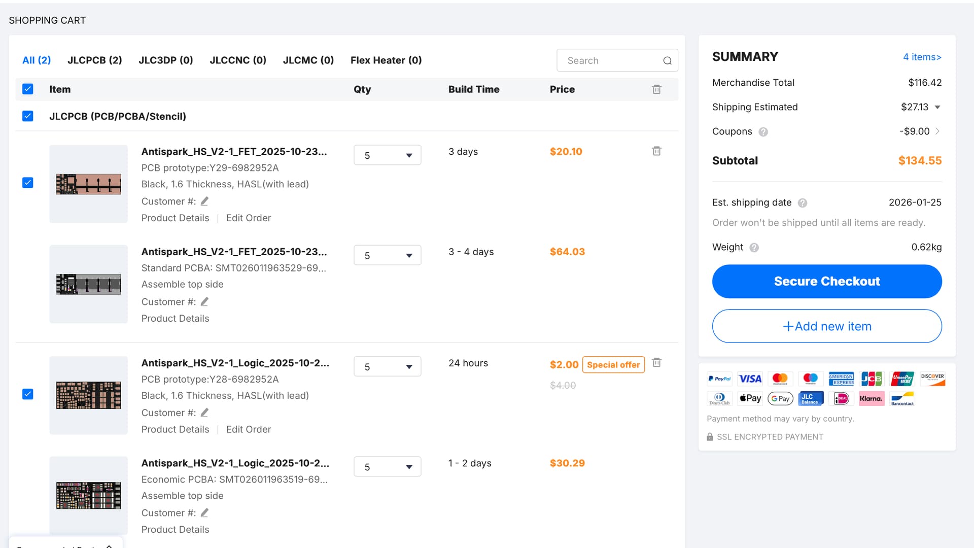
Well a 1-board solution will get quite big in terms of area, where 2 small boards like now you can stack
Also the FET PCB benefits from ALU PCB, while the logic needs 2-layer
from the pictures i have one wish/suggestion: put some mounting holes or at least some free space on the pcb’s sides so it can be mounted / stacked in an case.
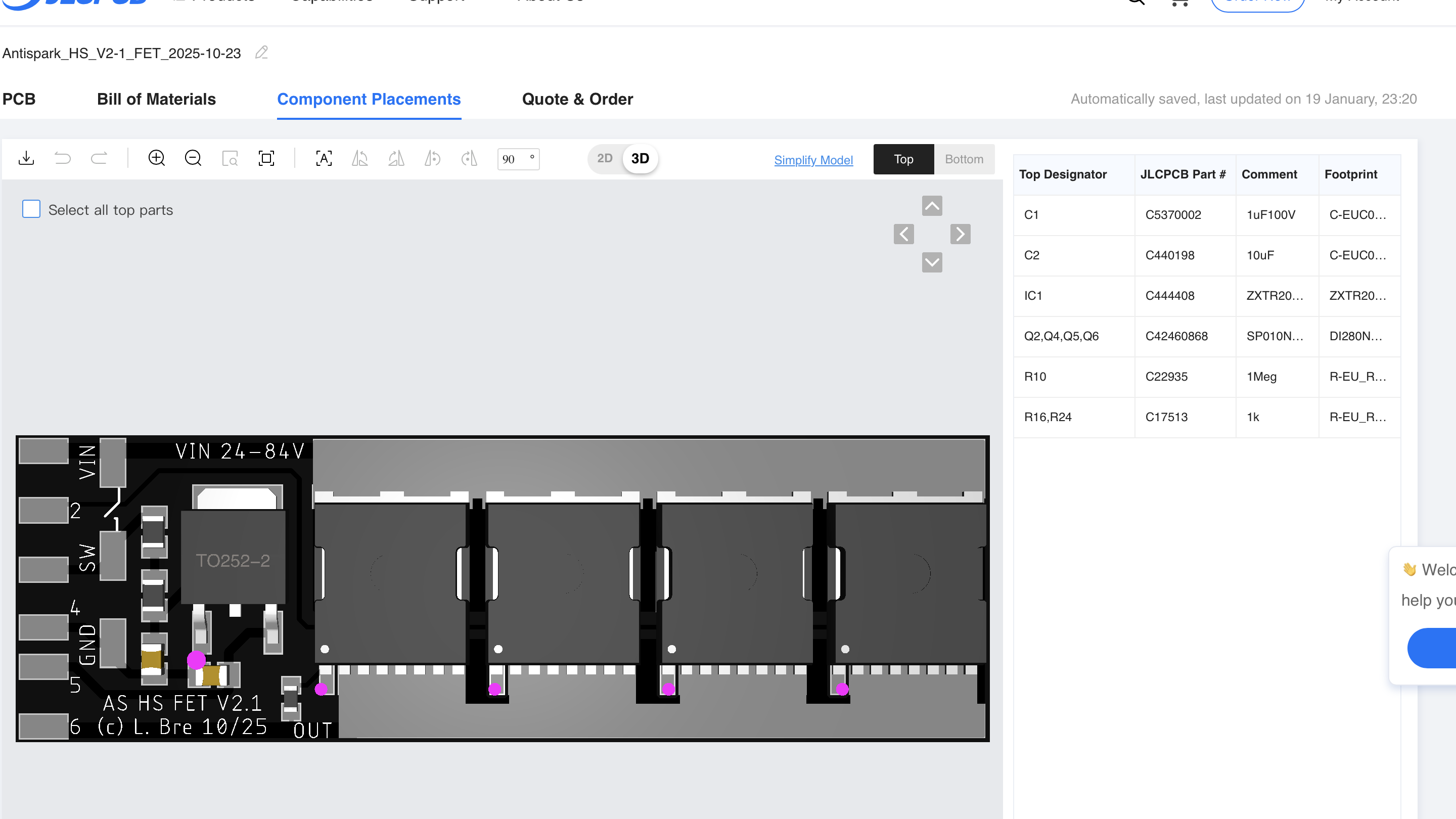
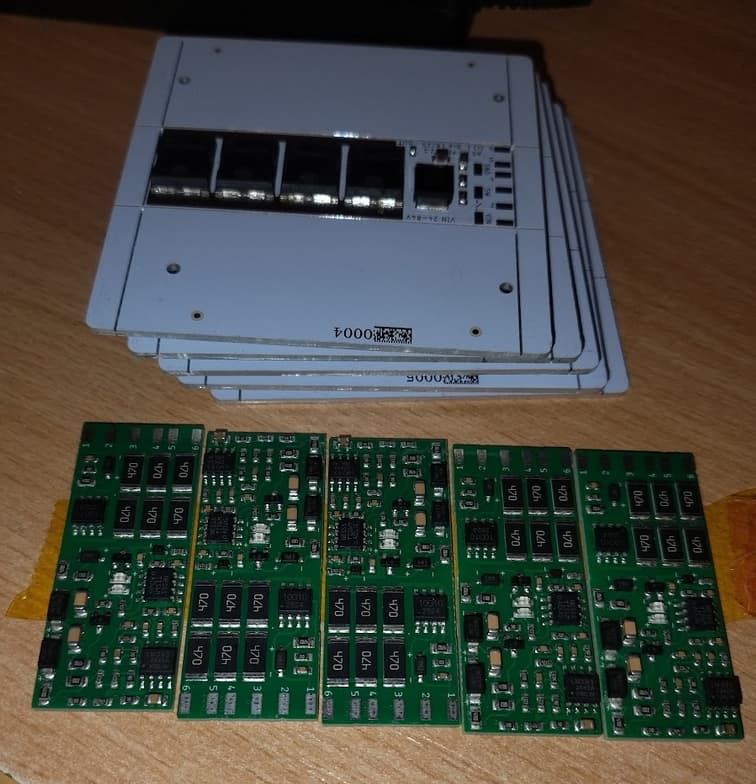
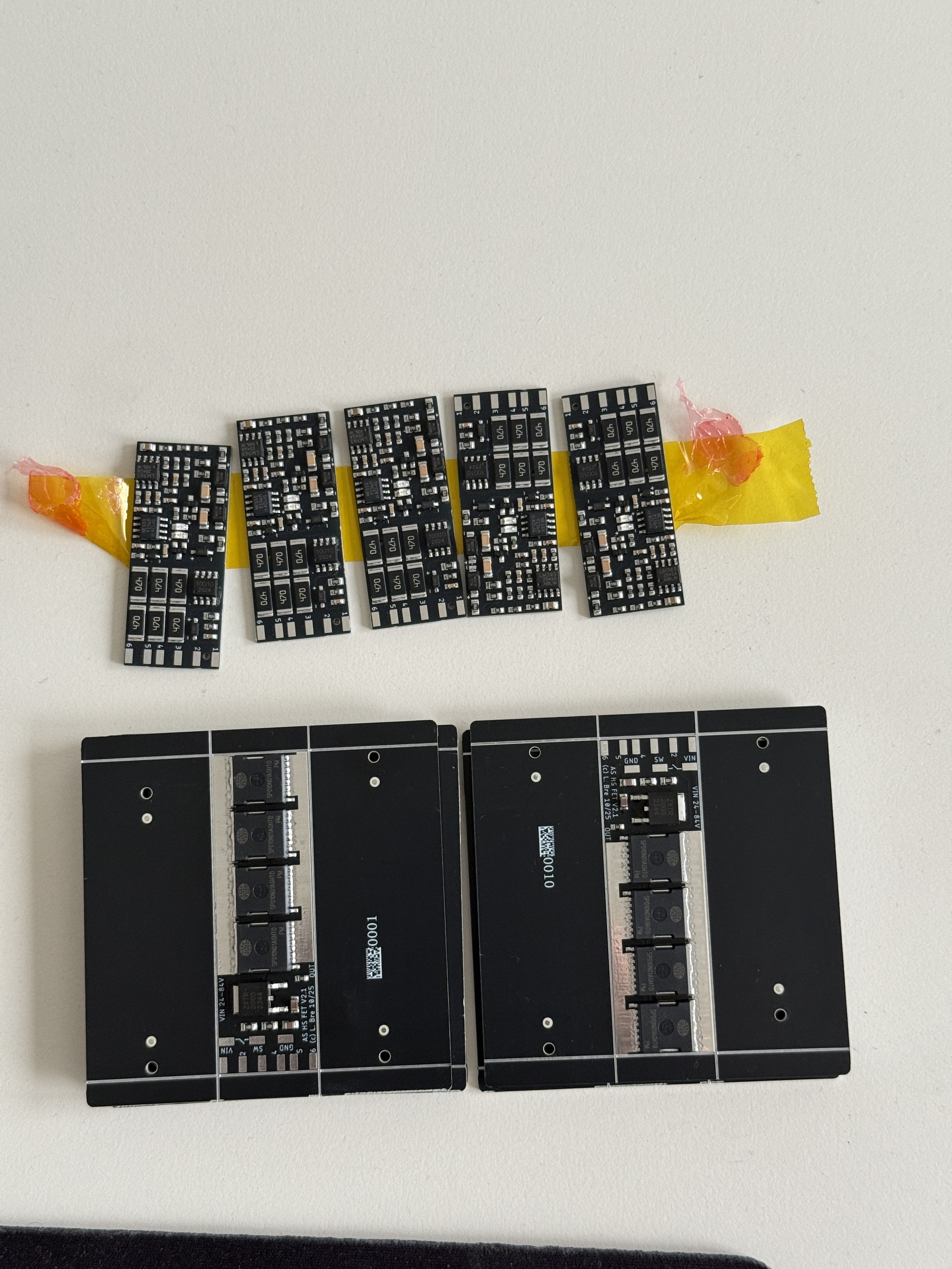
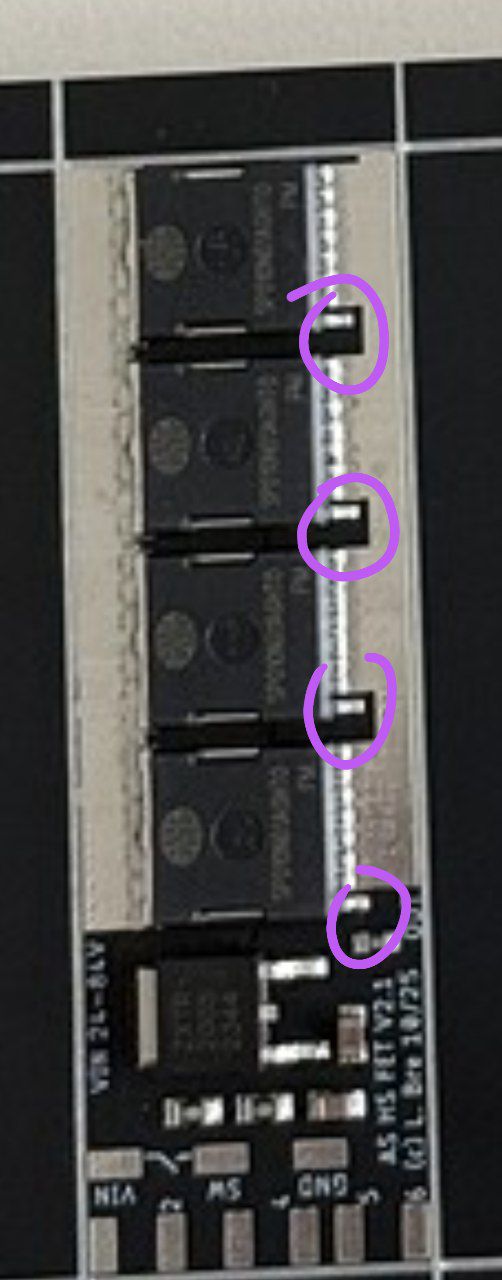
Is this how it is supposed to look like after soldering?
If we leave the aluminium sides and just not cut them we get one big heatsink but the issue is that the exposed metal pre-cuts rails from jlcpcb are dangerously close to the designed solder pads.
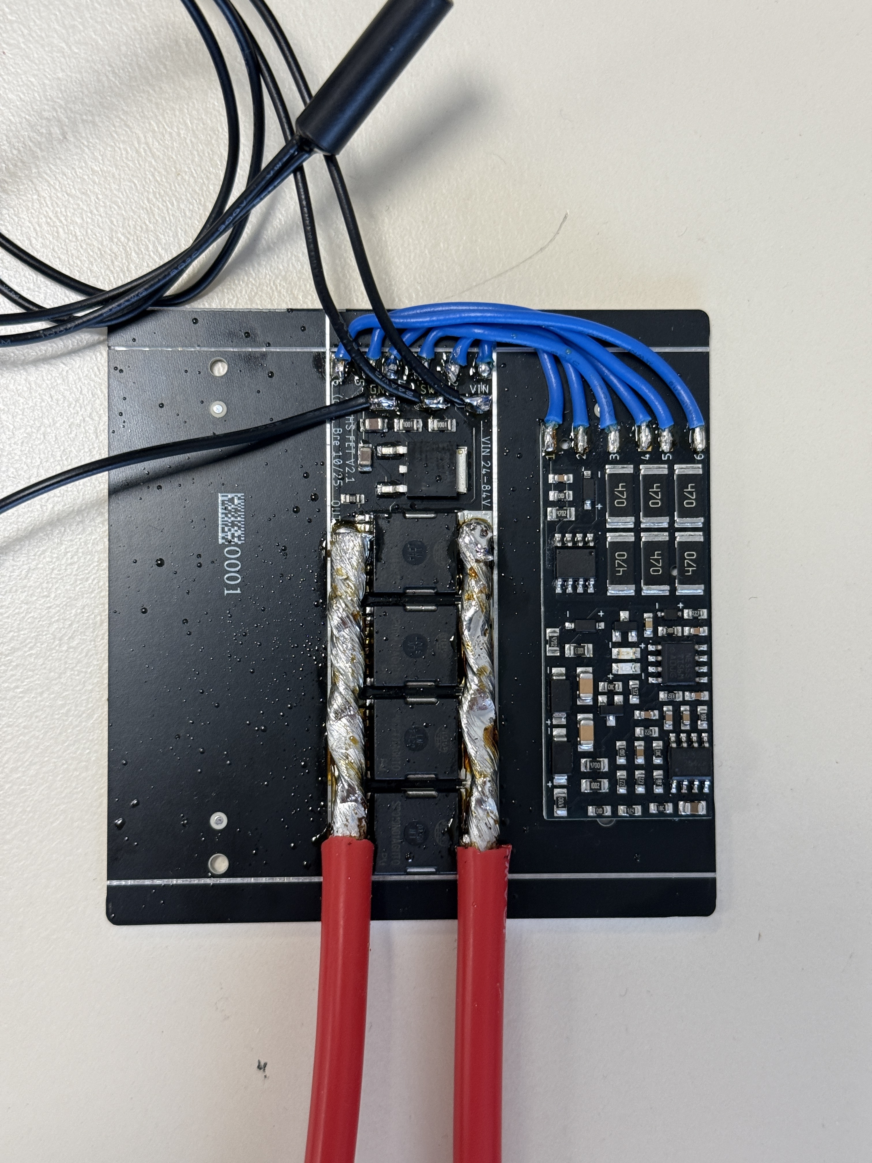
The wire looks like you will only draw 50A or so? Otherwise it’s probably too thin?
Also make sure you don’t bridge the 1st of each mosfet when you solder it like that!
Exactly one more thing why the soldering pads should be wider in my opinion.
The wire is 10AWG. Would it be ok if i only soldered the wire to the one mosfet at the start of the pcb? Not like in the picture where i paid a lot of attention to solder it carefully as close as possible to each 4 of them?
Is the solder pad thick enough and i just made a lots of nonsense work there?
Best case solder 4 wires, one to each mosfet, join later if you want the full current
4mm² for 50A, so 4 wires for 200A, that’s how it was designed
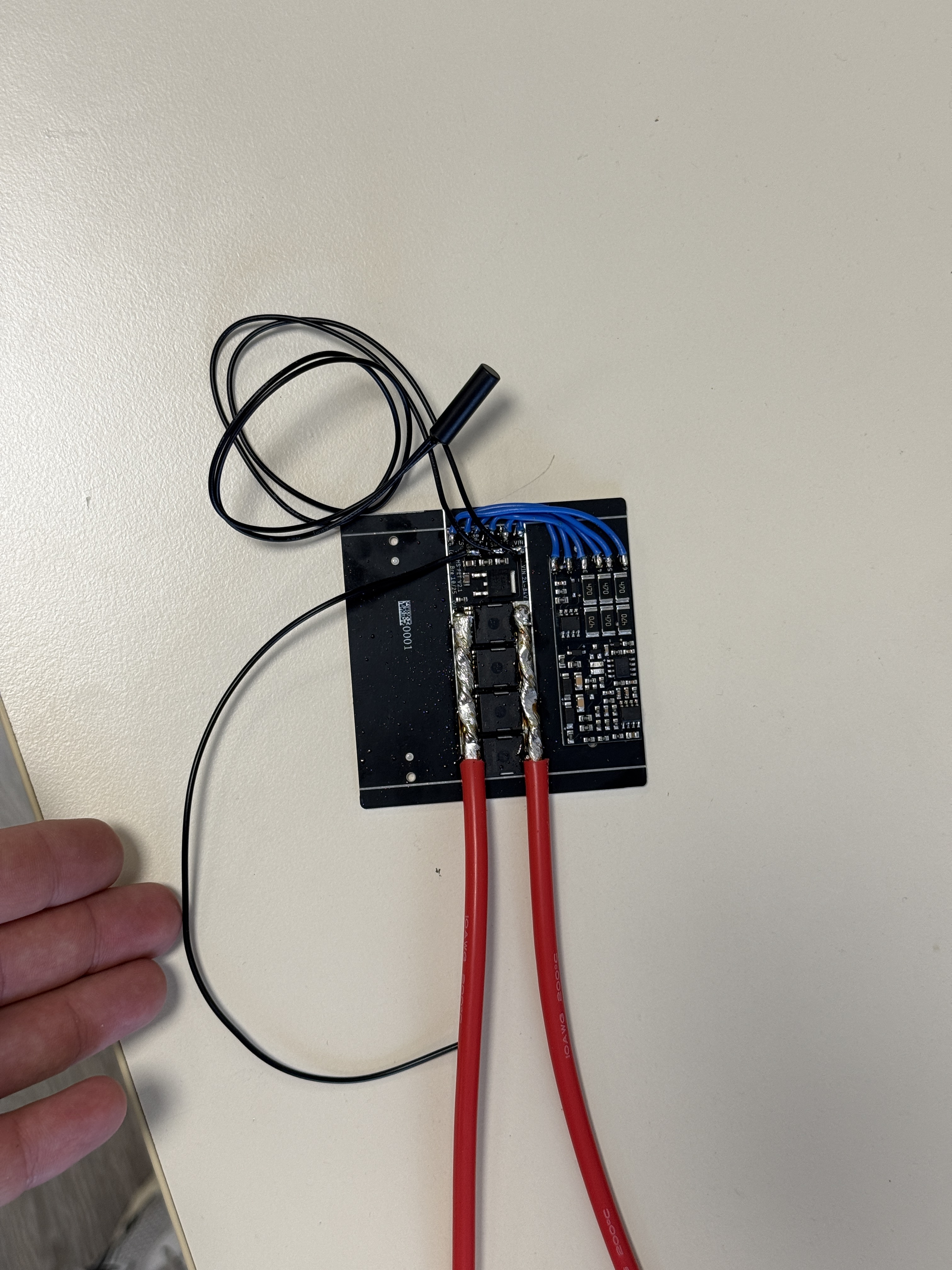
Understood. Well, it will still work like I did it but it’s just not as nice.
I measured conductivity and there seems to be no issues, would you recommend checking anything else, anything specific before first power up? With voltmeter
Since all Gates are connected, you can just measure from the Gate pin you can reach towards the battery contact, no contact= good