Exact! And also more cost/current compared to N-ch
2 Likes
Is the latest version available on JLPCB ? I know it may be not the final version, but I would like to order few pieces ( I am building 3 batteries right now) and want to integrate it there - even if I have to fix/replace it later.
Really good work ! Thanks @ludwig_bre for this and your inspirations/videos about batteries build ( mine and my friends are based on your examples)
1 Like
I will be able to share 2nd week of January
1 Like
Short update:
Finally found time to power up my new revision of boards
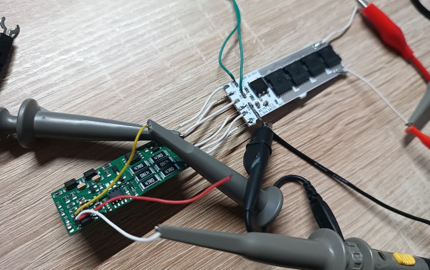
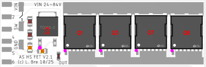
As you can see the design was split between the power and the logic board
Had a small bug still, that could be solved by swapping a resistor for a capacitor, so no new layout needed
Tested the logic (soft start, short circuit detction,…) at 24V and 84V succesfully
Next up: Testing the power handling capability @200-300A
5 Likes
Amazing Ludwig.
Just to clarify, a simple reed switch (Normally open) will be suitable for this right? Seems like yes from the schematics but just want to be sure.
Yes any switch that can handle battery voltage and 10mA of current
Now that i started to think about I discovered that i have the ones that are “rated” at 30V DC. Link: https://www.aliexpress.com/item/1005005334347658.html?spm=a2g0o.order_list.order_list_main.163.4c441802t2yioq
Do you have any experience can i supply them with 60V ? Also they seem to be two versions: AC and DC and one goes up to 200V.
Would AC 200V reed switch from that link above be better than this 30V DC ?
Ah you are talking about industrial (digital) sensors
Those have their own circuit inside and will draw standby power as well as being limited to a certain voltage
I would recommend using a passive reed sensor like this:
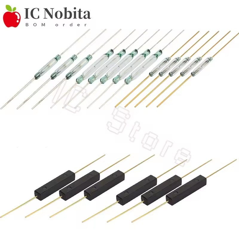
Hmm, there is no indication of electronics inside of them, i think they are passive? How to check? Would they not require at least three wires for that?
Checking continuity with Voltmeter right now and it seems they behave as they should. I dont see an option how could they be powered if they are NO ?
Also looking at these to buy: Option 2
So - how is the testing going ? Some time ago you mentioned that you would share the final version (to be manufactured on JLPCB)
Did not have time yet to validate high current and thermal behavior
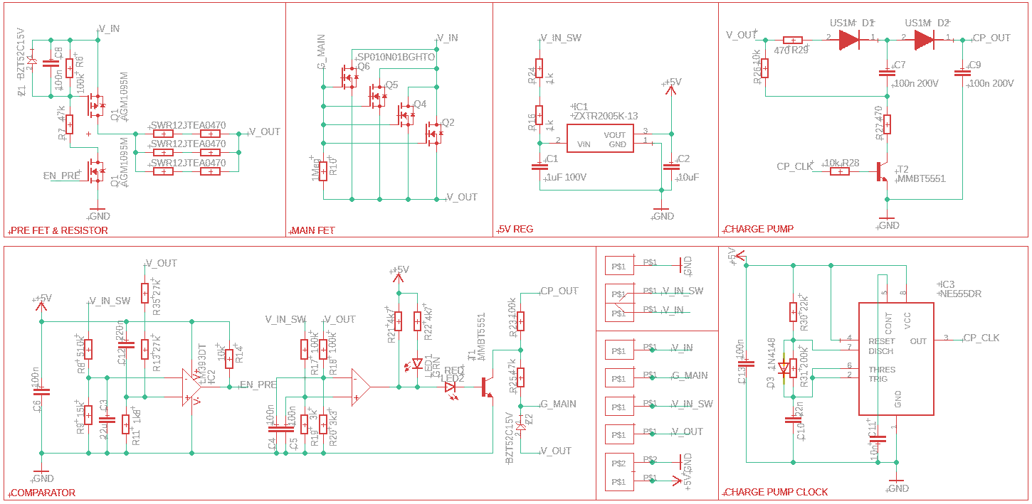
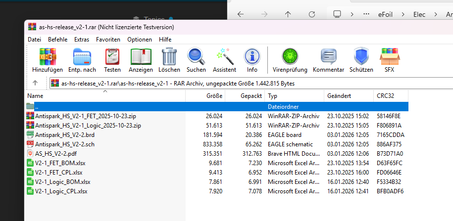
Anyways here is the current status of files
Order instructions: FET PCB order as Aluminum, 1-layer, 1.6mm thickness
Logic PCB as FR4, can be 0.8mm or 1.6mm, does not matter
Assembly instructions:
Attach logic to FET PCB with 6 wires, 1->1, 2->2,…
Attach 4-6mm² (9-11AWG) wires close to each MOSFET (so in total 4x on the input and 4x on the output side) close to each fet
Attach the input and output wires to you connectors or load with similar length
Attach FET PCB to heatsink
Attach switch and GND wires to pads on FET PCB
1 Like
Thanks, will order few samples.
During normal operation - how much heat does it generate ?
I wanted to integrate it into battery box as safe on/off - but if this gets really hot then it would be unsafe.
Would it be enough to put FET PCB on the outer - with small radiator ?
Depends on the current you draw - the on-resistance is about 0.3mOhm
So to calculate heat:
Current² * 0,0003 Ohm = Watt
50A * 50A * 0,0003 Ohm = 0,75 Watt
100A * 100A * 0,0003 Ohm = 3 Watt
200A * 200A * 0,0003 Ohm = 12 Watt
Btw a M.2 SSD Heatsink fits perfectly ![]()
Well, I am in range 100A top - so 1…3W average
But in this case I will put it together with VESC - on my water cooling plate ( to be safe)
Thanks for sharing, Ludwig and the excellent work. I’m looking forward to use this in some projects. I searched for other alternatives and none gave the features.
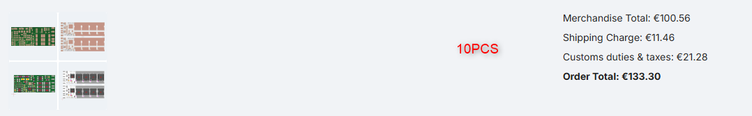
I did PCB designs and ordering before, but not assembled and at JLCPCB. As a hint for others: The upload to JLCPCB worked only for me after unpacking all data and packing it into a zip file.
To Ludwig: Is it correct, that the file includes only the FET PCB? Also, the pick and place files are missing, right?
The file I uploaded should contain this
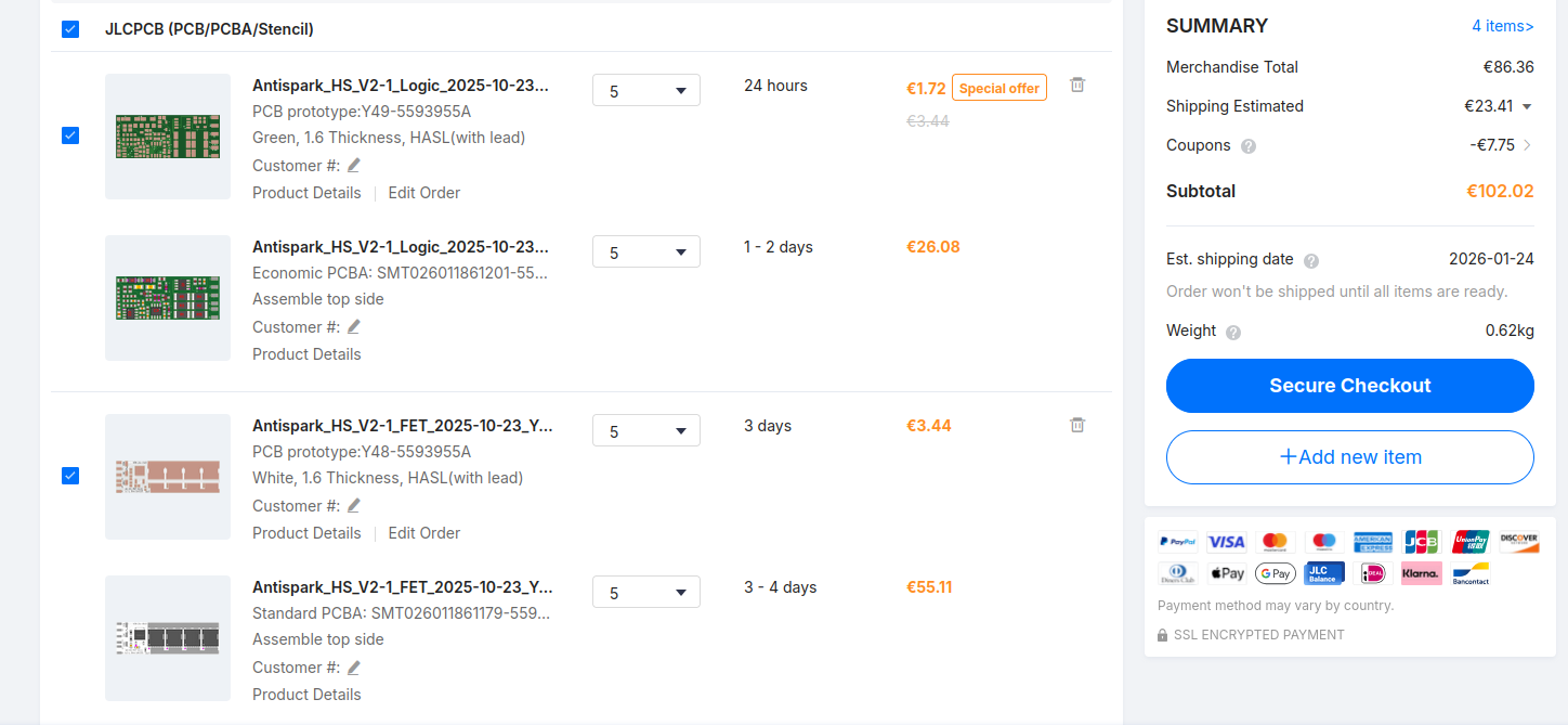
Upload each the .zip files to the “order” page at JLCPCB
Later continue on the bottom to “assembly service” or similar
You will eventually be asked for a BOM and CPL file, upload the matching ones (the four .xlsx files)
Done!
Only unpack the archive you downloaded to get the files you can see above
Nothing to unpack and repack besides that!
Ah! It does actually. But not if you use 7zip. Then apparently only the content fromt the 1st zip file is shown. Thanks!
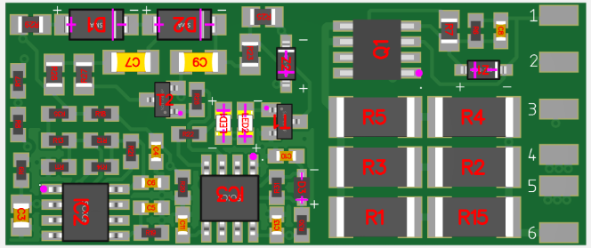
The 47R needs to be a special kind… surge rated
Replace only with this P/N: C2765607 (1200 in stock)
For all important parts the BOM always lists the compatible alternatives (alt.: )
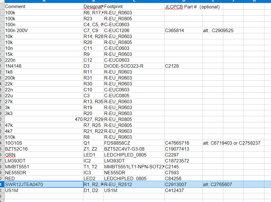
Good to know you have listed alternatives - JLPCB itself does not seem to see it when loading CPL file.
I have selected matching parameters manually and ended up with exactly same part number you had listed.
2 Likes