I finally finished my first big DIY battery pack, and I’d love to hear what you guys think, especially if you see anything I could improve next time.
The goal was to build a waterproof, vibration-resistant Li-ion battery that I can use for my e-SUP, e-buggy, e-trike and other future projects. The final pack is 12s18p, about 50.4 V full, 43.2 V nominal, 58.5 Ah, and roughly 2.5 kWh.
This is my first battery pack of this size, so I’m definitely open to critique.
I rebuilt it from my old 4s4p packs that I had made for another project. They had only seen about 3 cycles and were stored at around 3.8 V/cell in a cool, dry place, so they were still in very good condition.
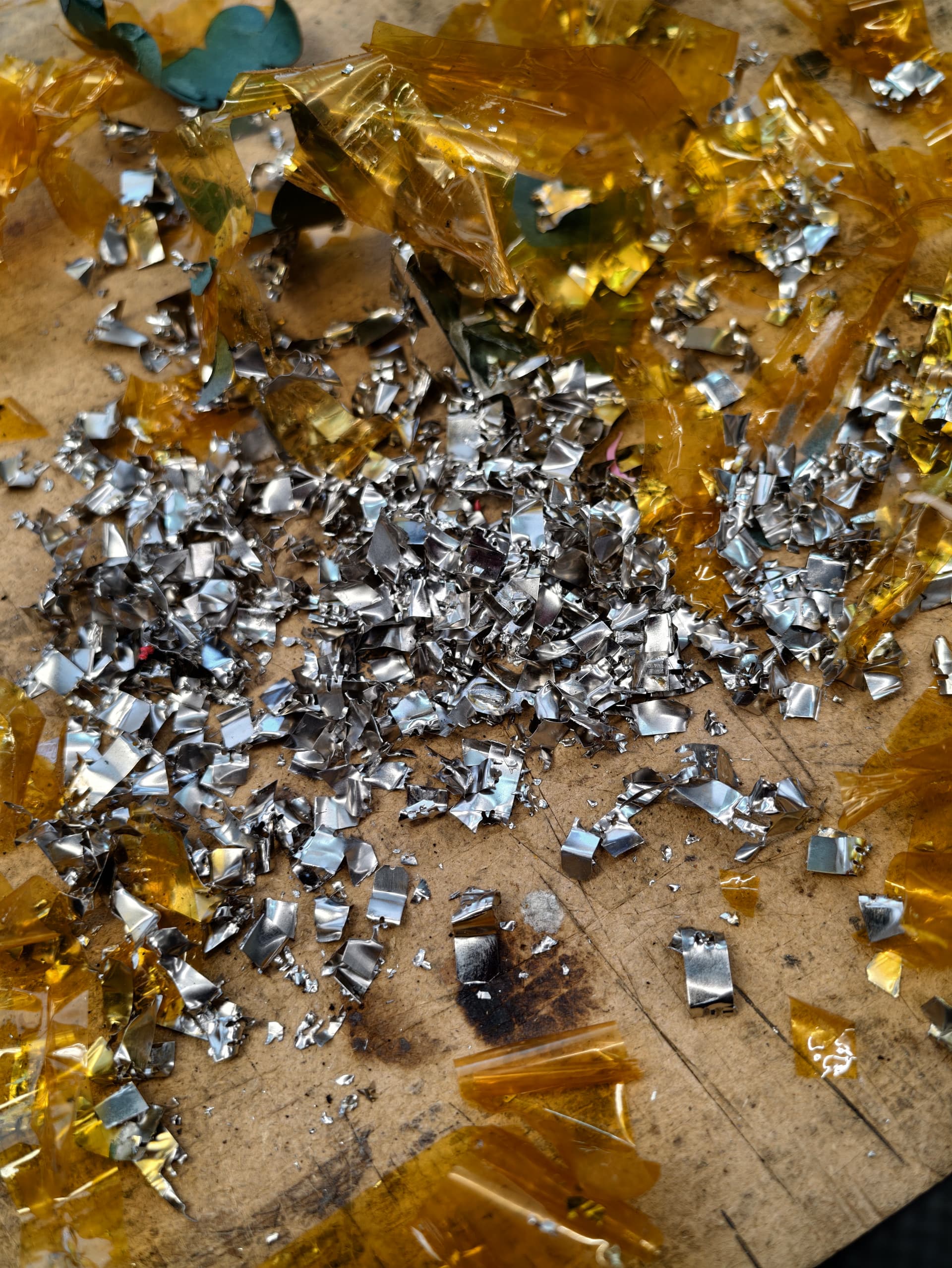
Before taking them apart, I brought all packs to the same voltage (slighlty discharged state - safer to work with). Then I disassembled them carefully and removed the old nickel strips. Honestly, that part was the most annoying and stressful, because one careless tool movement could short a cell.
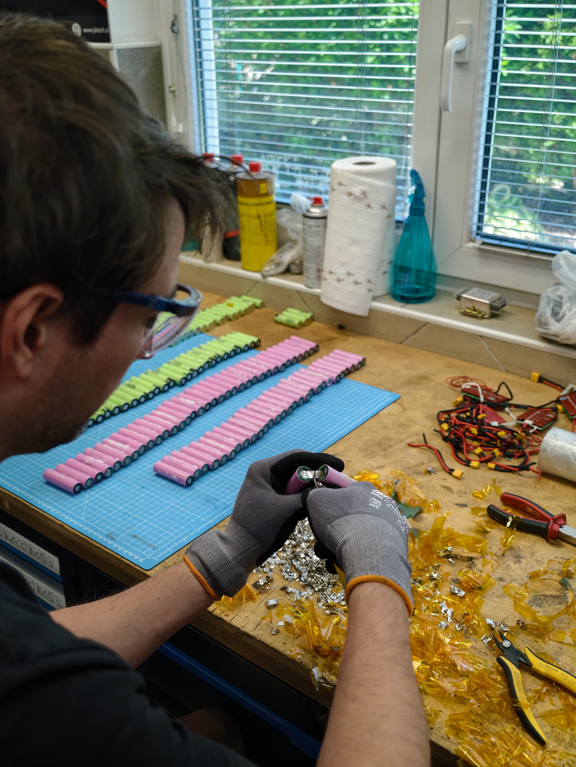
After disassembly, I cleaned and visually inspected all cells. I lightly removed leftover weld high spots from the terminals (my DIY rotary tool adapter, square stone), measured voltage and internal resistance of every cell, and sorted everything by IR.
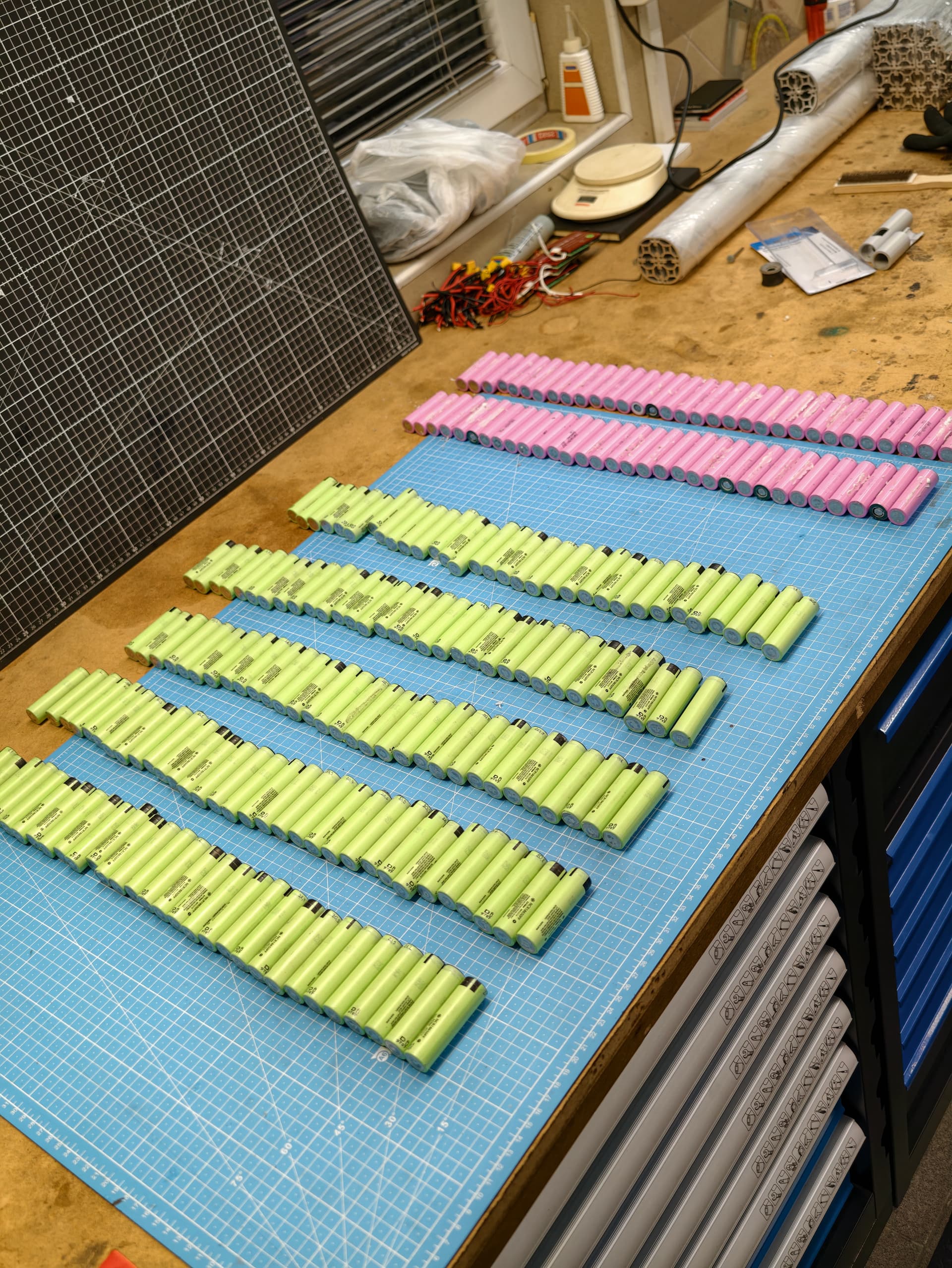
I used two cell types: Panasonic NCR18650PF, around 21 mΩ, and Samsung 30Q, around 13 mΩ.

I know mixing cells is something to be careful with, so I made every parallel group identical. Each 18p group has 13 NCR18650PF cells and 5 Samsung 30Q cells. That way each group has the same chemistry mix, same capacity, and same total internal resistance.
I also distributed the 30Q cells evenly through the pack so there wouldn’t be one area carrying more current or heating more than the rest.
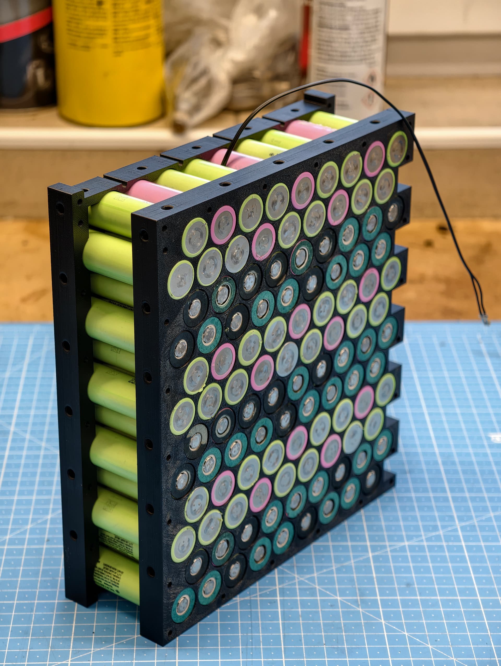
I designed and 3D printed my own PCTG cell holders. I did a few test prints first because the two cell types were slightly different in diameter, and even the positive and negative ends were a little different.
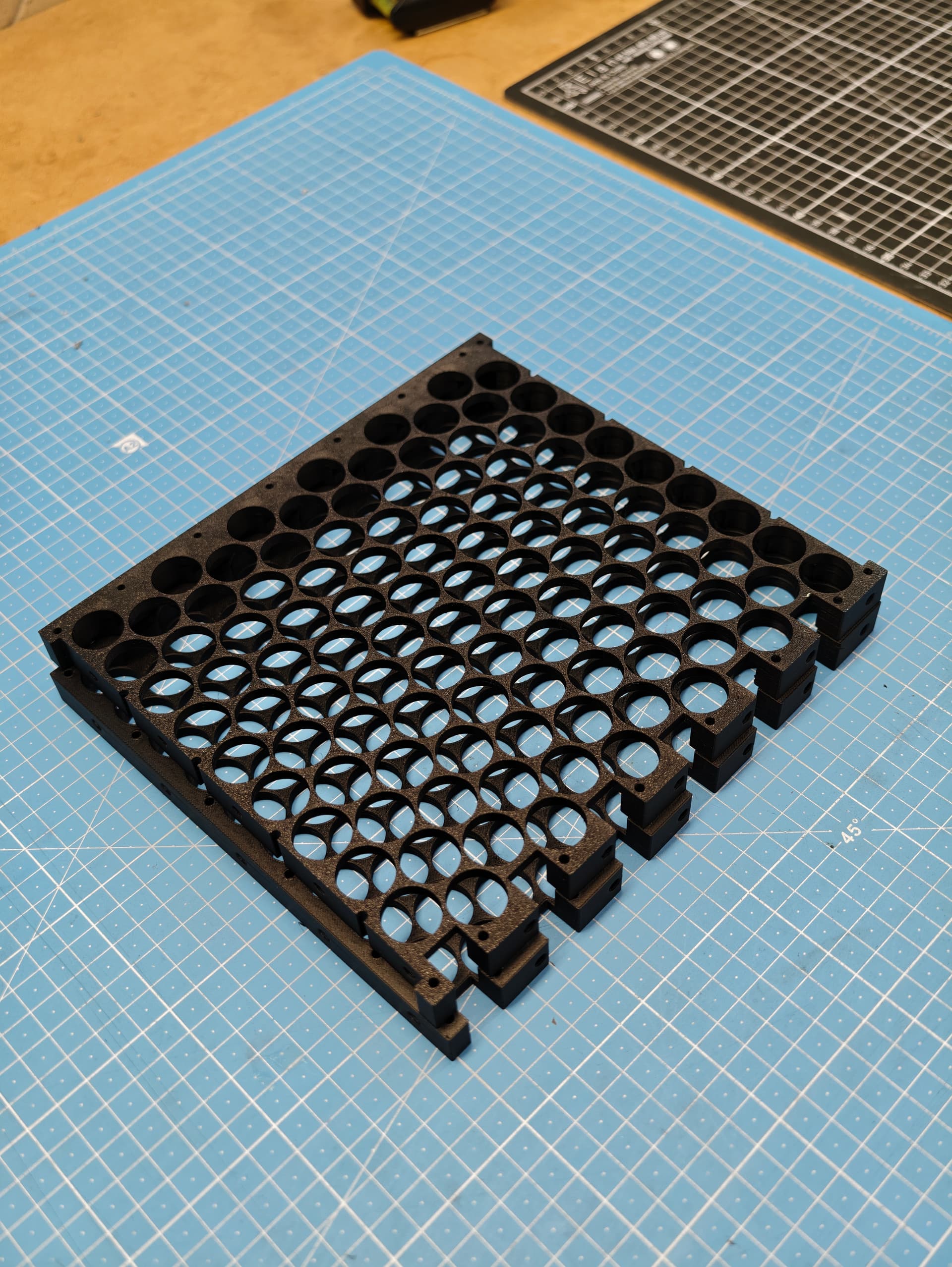
The nice thing about the holders is that they make wrong assembly much harder. Wrong orientation or wrong cell in the wrong place simply doesn’t fit properly.
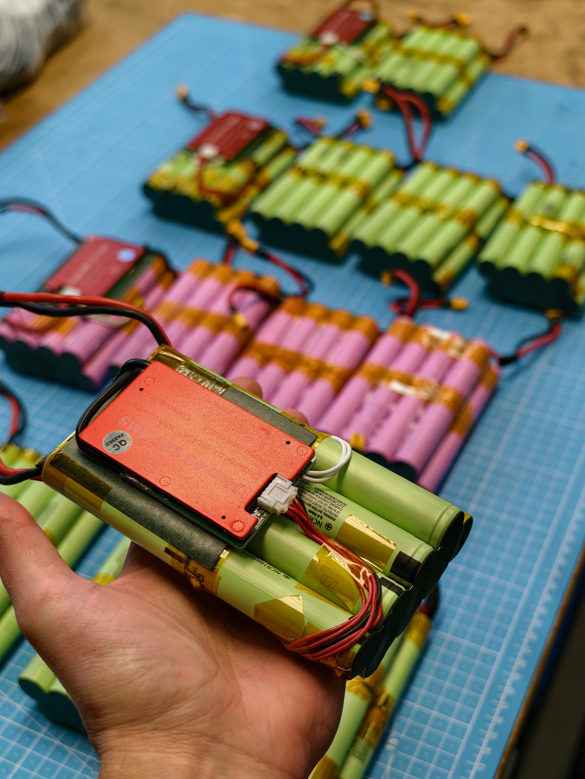
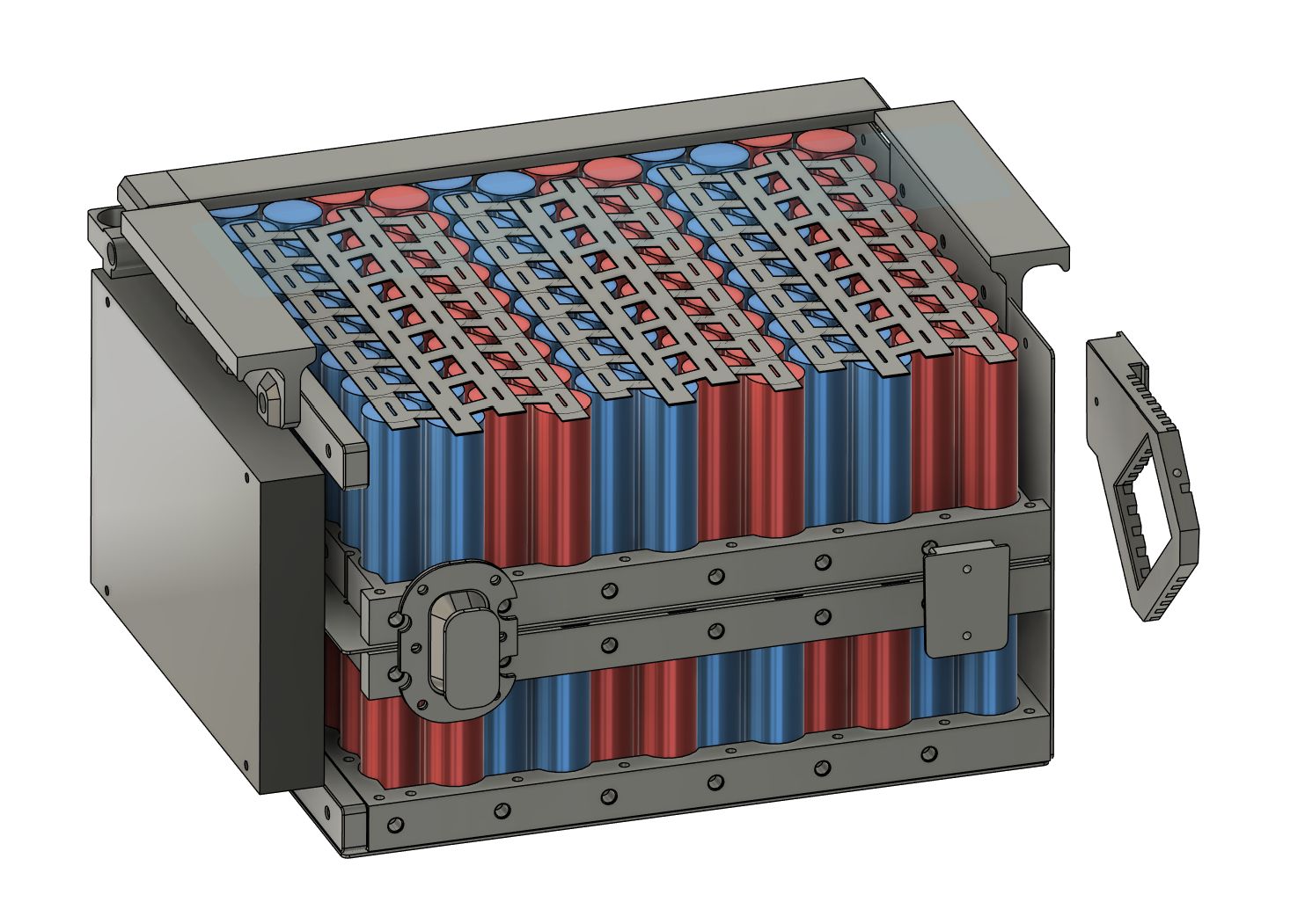
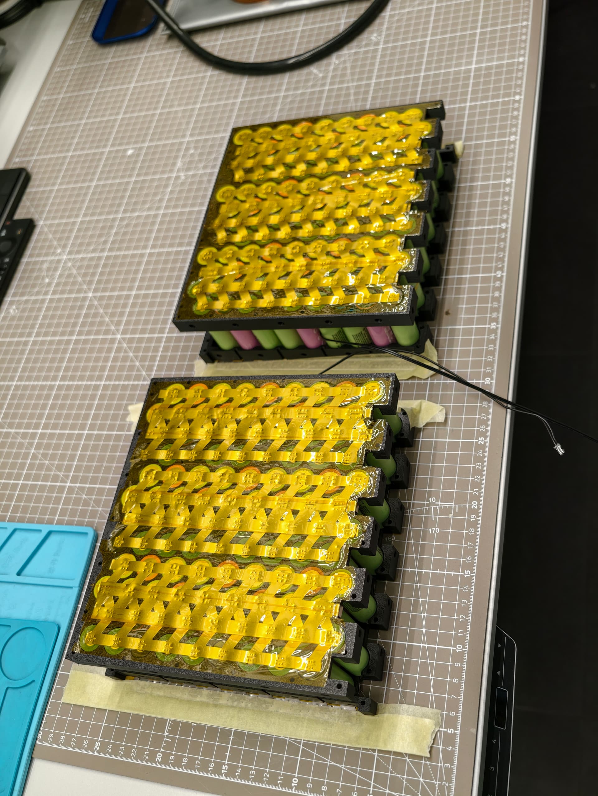
The battery is built as two 6s18p plates, then connected in series into 12s18p.
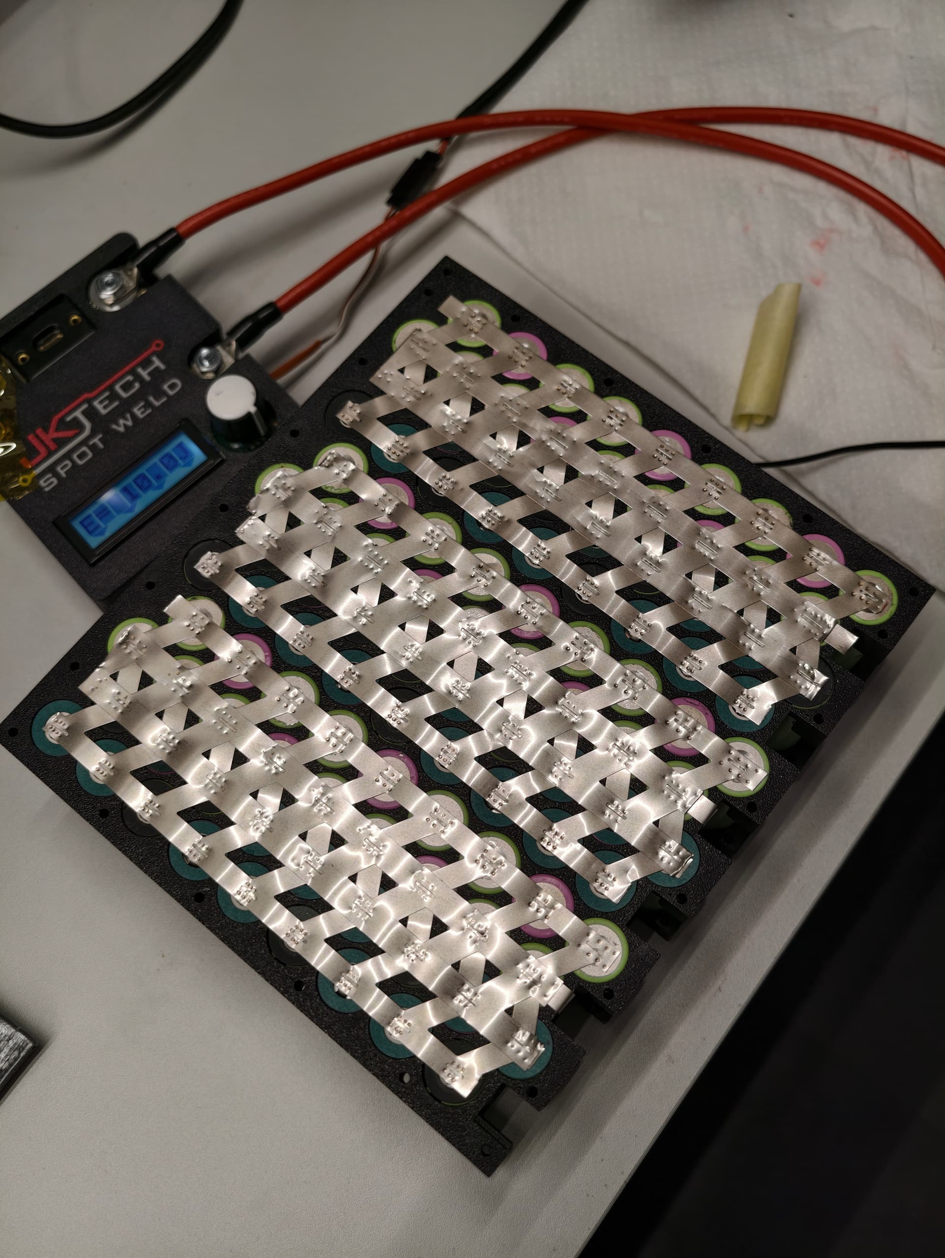
I used pure nickel strip, not plated steel. First I welded the main strip, then reinforced the series connections with extra nickel.
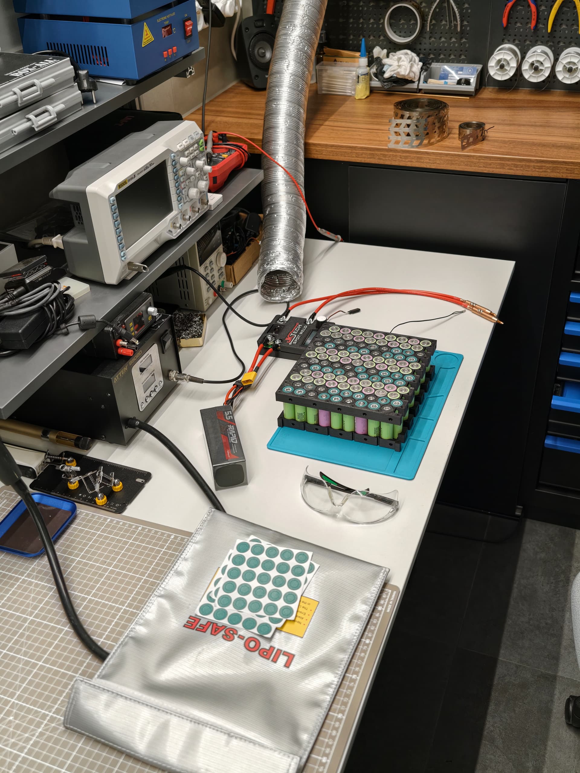
Before welding, I replaced damaged fish paper rings where needed, cleaned cell terminals and nickel with IPA, and did peel tests on spare cells to dial in the welder settings.
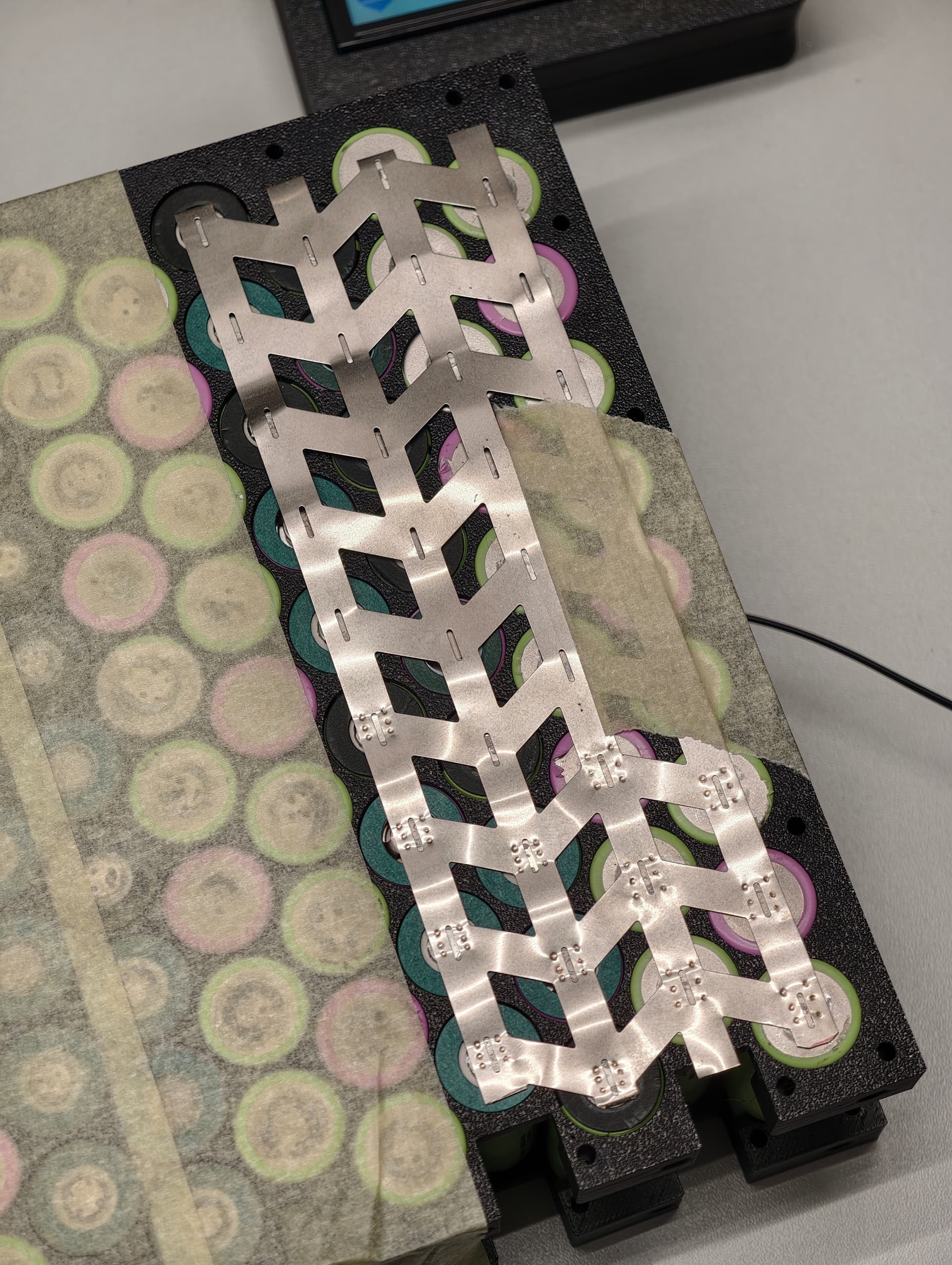
The welding settings were 20 J for the thicker/main strip and 12 J for the added strip. I ended up doing something like 2400 welds total. A lot of work, but I’m happy with how it came out.
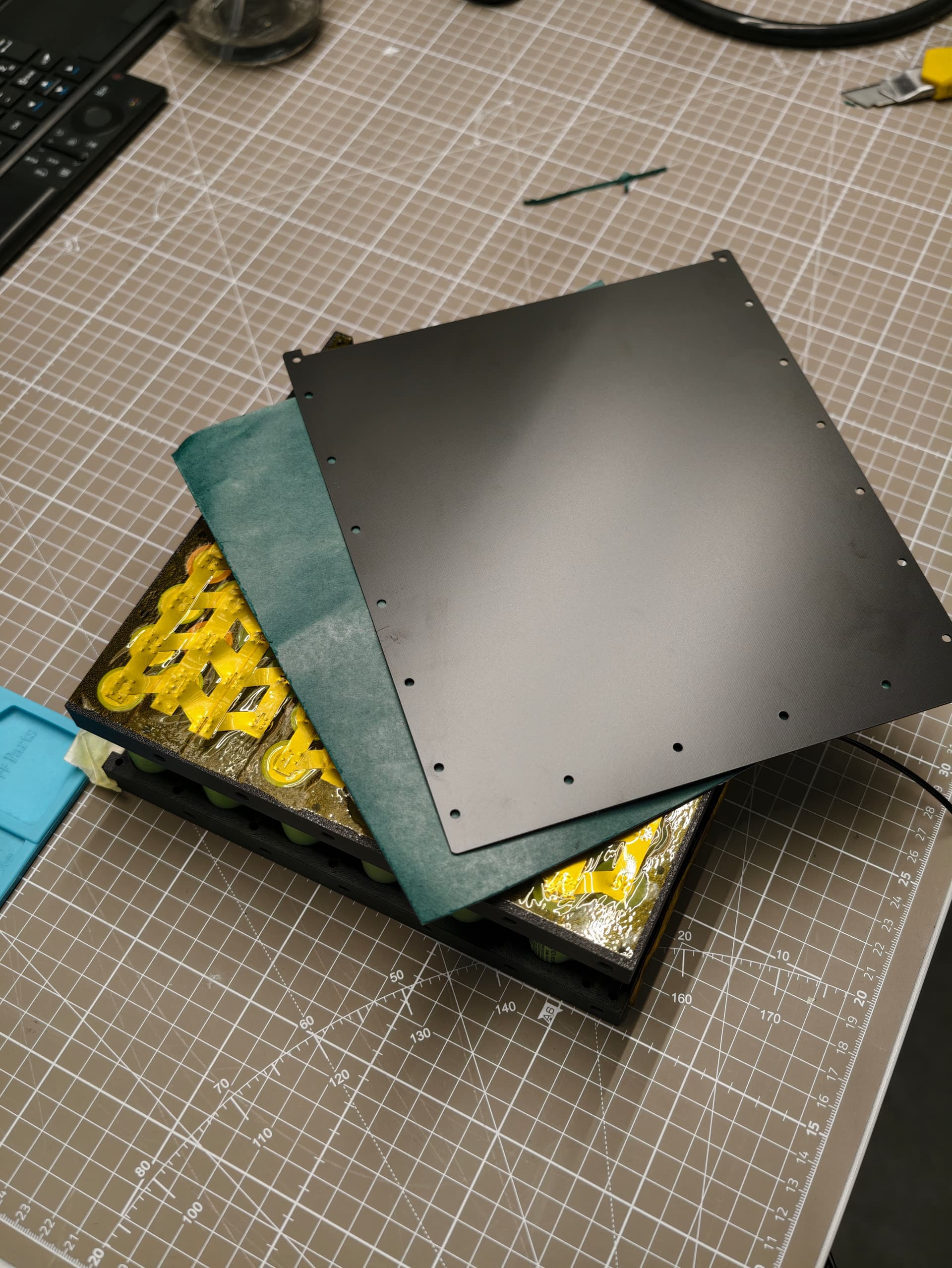
After each plate was welded, I covered it with Kapton tape and fish paper. Between the two battery plates I added a 1 mm FR4 sheet, slightly oversized, to separate the two halves and busbars.
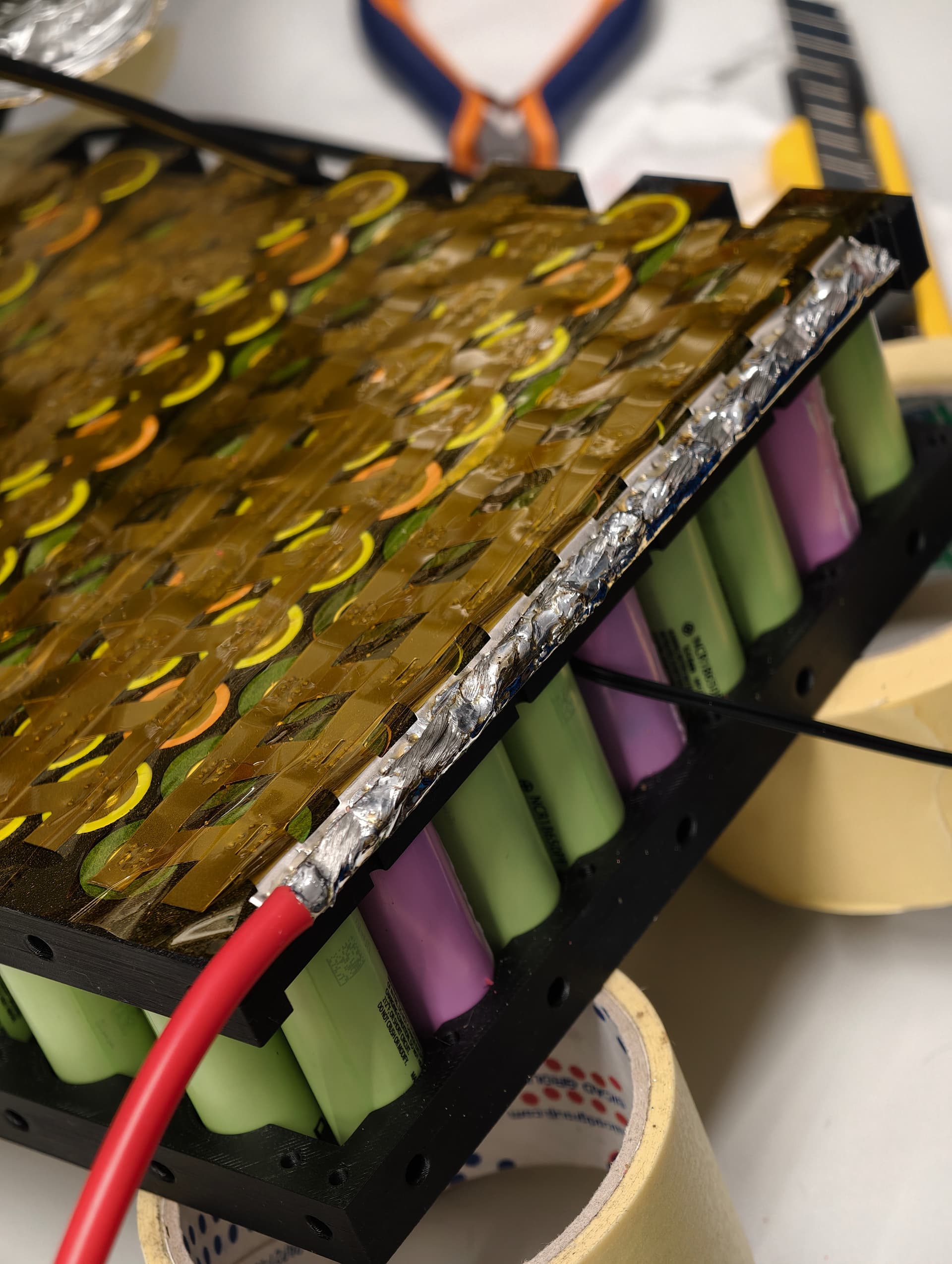
The pack stack is basically FR4, fish paper, Kapton, first battery plate, Kapton, fish paper, FR4, fish paper, Kapton, second battery plate, Kapton, fish paper, and FR4 again.
I also added NTC temperature sensors in the middle areas of the pack before final assembly, so the BMS can monitor the places where I expect the highest temperatures.
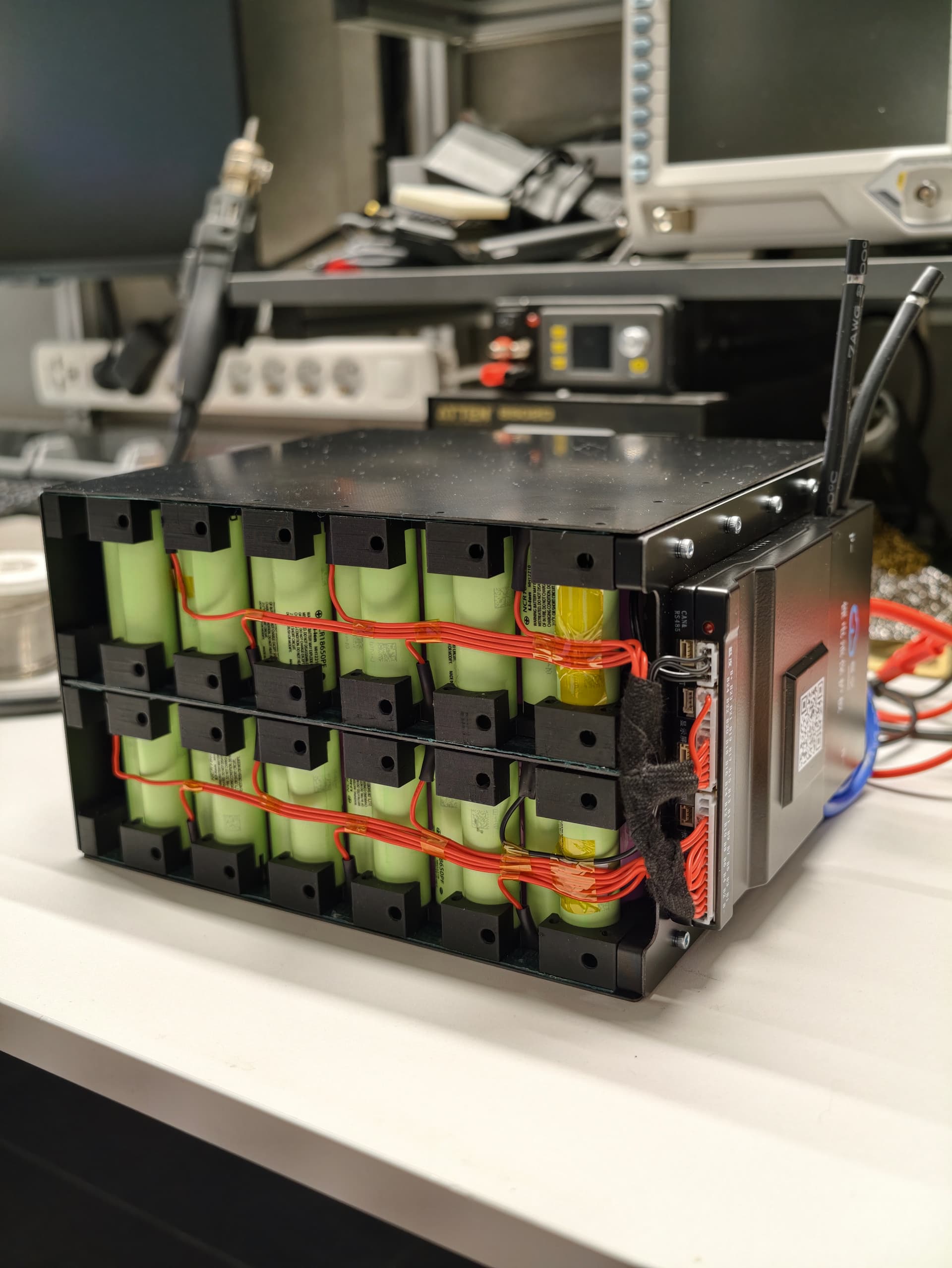
I used a 300 A smart BMS. This is total overkill for my current use, but I want this battery to be reusable for future projects too.
For the main current path, battery negative goes to the BMS with two AWG6 cables, and battery positive is also AWG6.
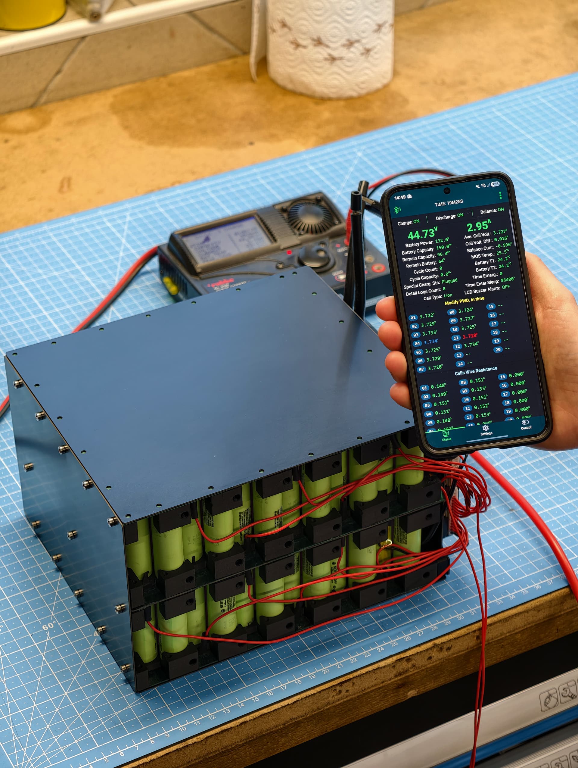
The BMS has Bluetooth, so I can set protections and monitor the pack. I also enabled a sleep mode where it disconnects the output after about an hour of inactivity, so the external terminals are not live all the time and idle drain is extremely low.
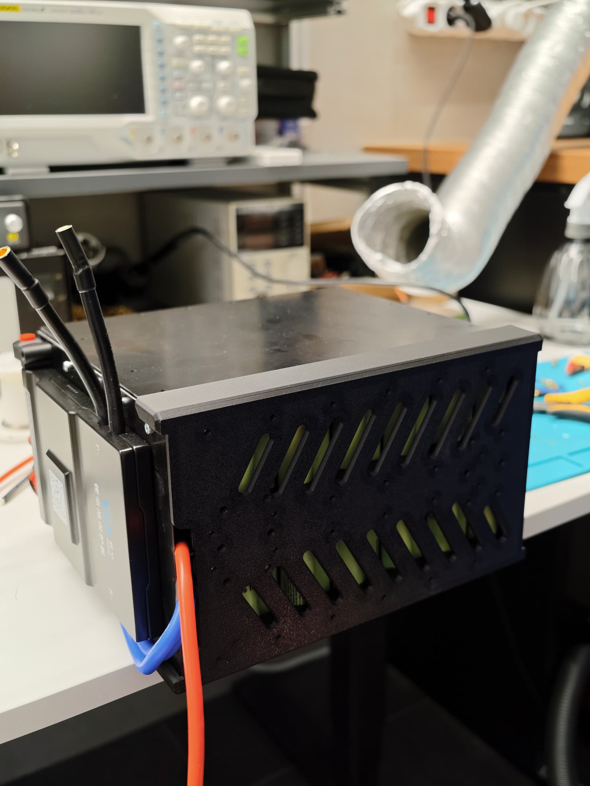
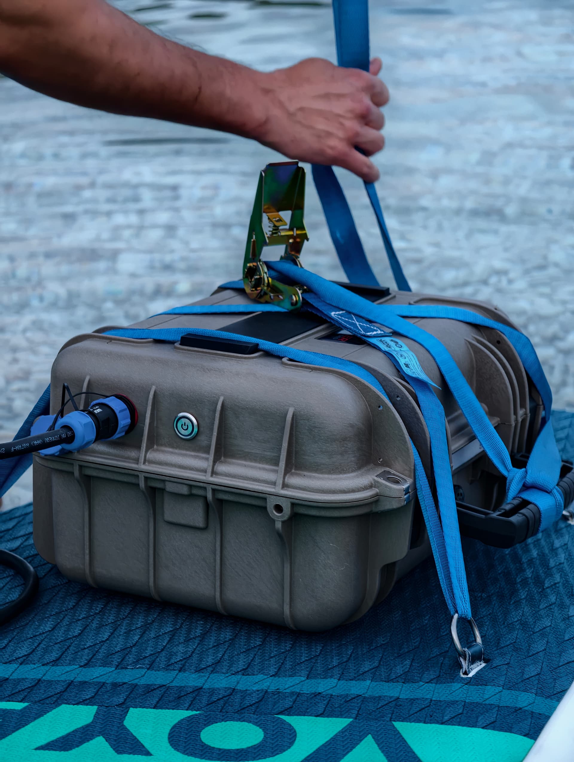
The whole pack goes into a waterproof case, but I didn’t want it rigidly bolted in.
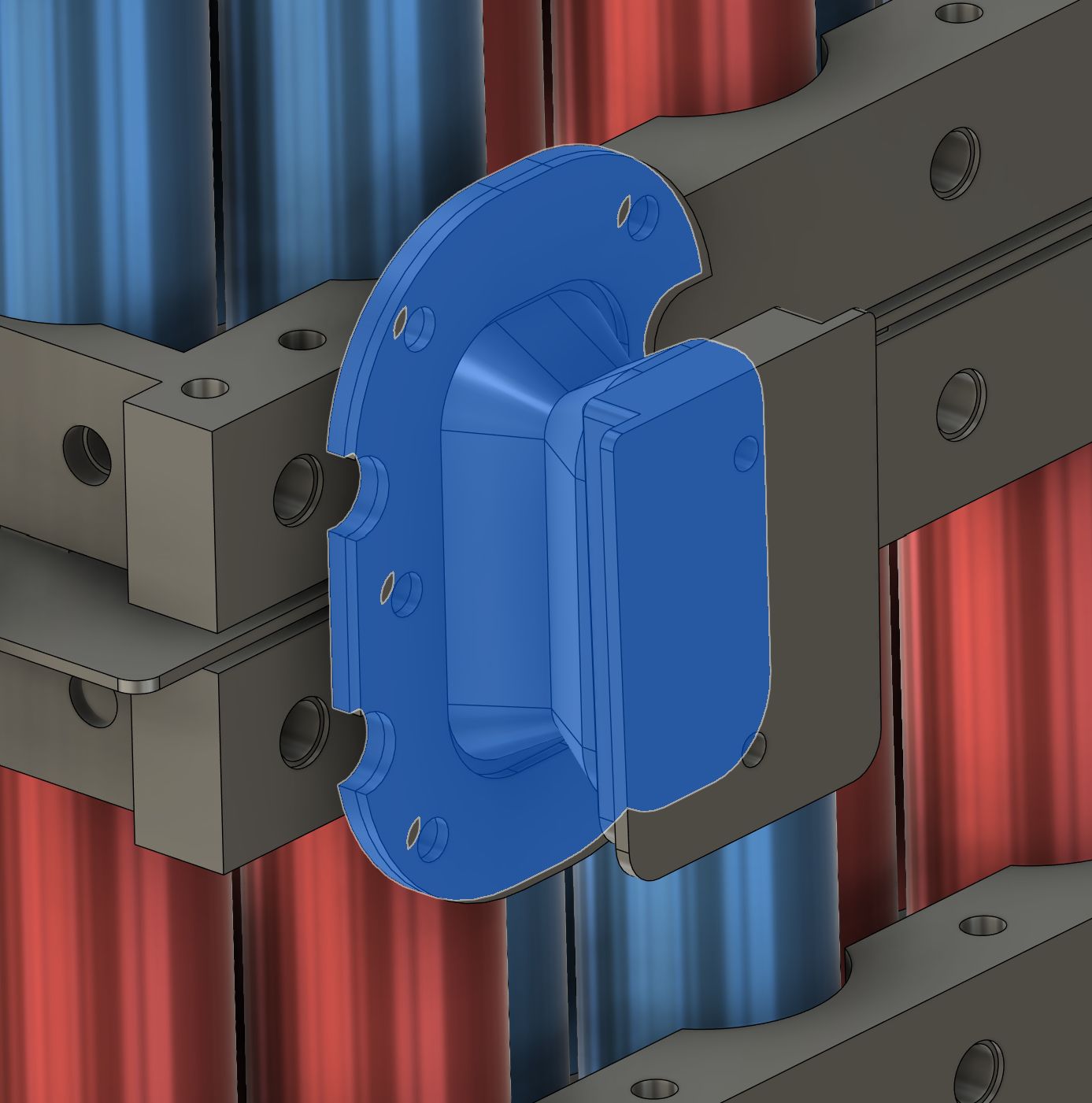
So I made TPU dampers and CNC-machined aluminium holders so the battery kind of floats in the center of the case. The dampers allow some movement in all three axes, and I also added soft rubber underneath so the battery weight isn’t permanently deforming the TPU.
This gives me two main benefits. First, the pack is suspended in the middle of the box, so if a little water ever gets inside, it still shouldn’t touch the battery immediately. Second, the pack is isolated from vibration and shock, which should help the welds, nickel strips and internals survive rough use.
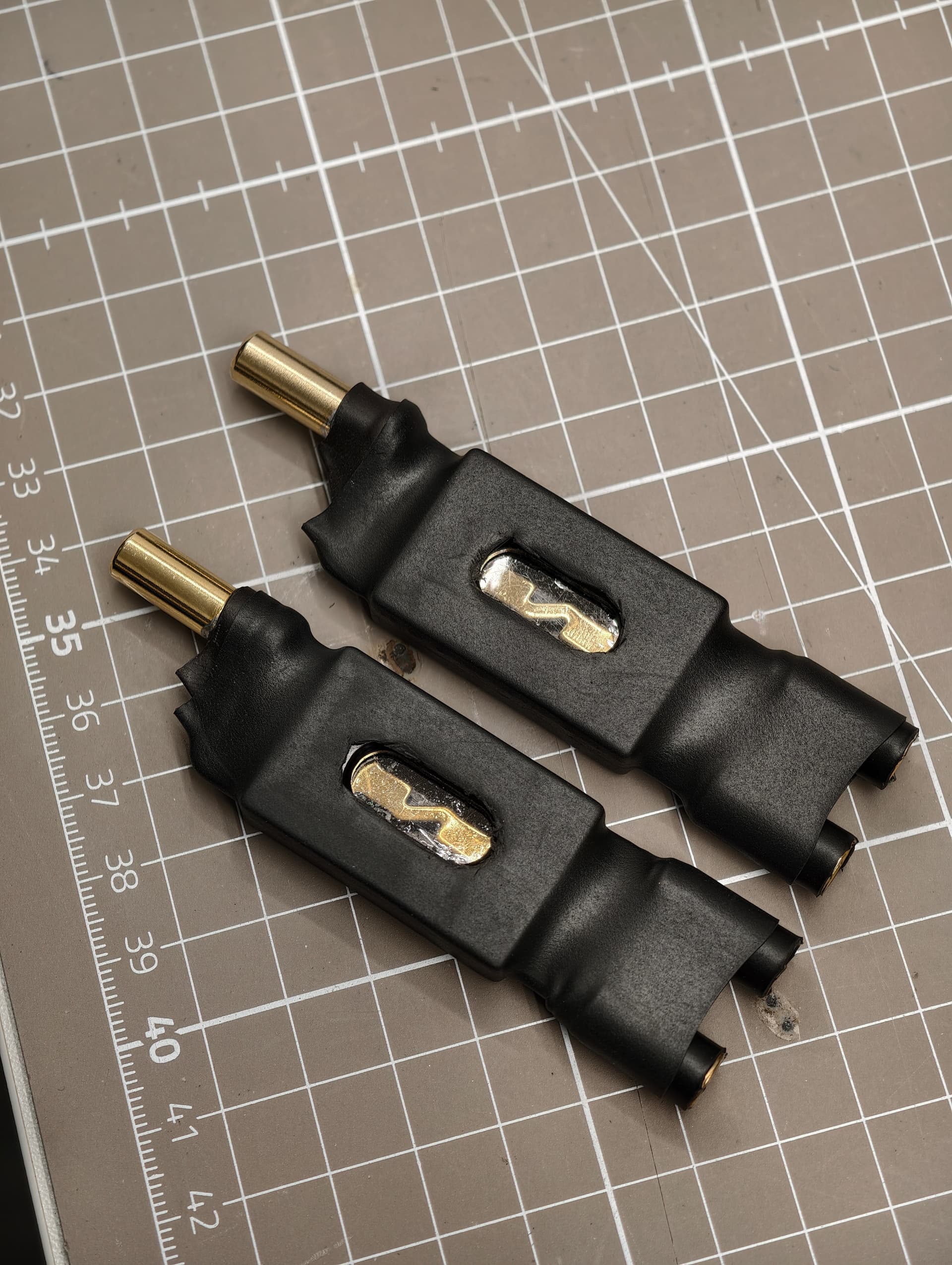
On the battery positive I added a 150 A fuse for the main output and a 50 A fuse for the auxiliary / charge output.
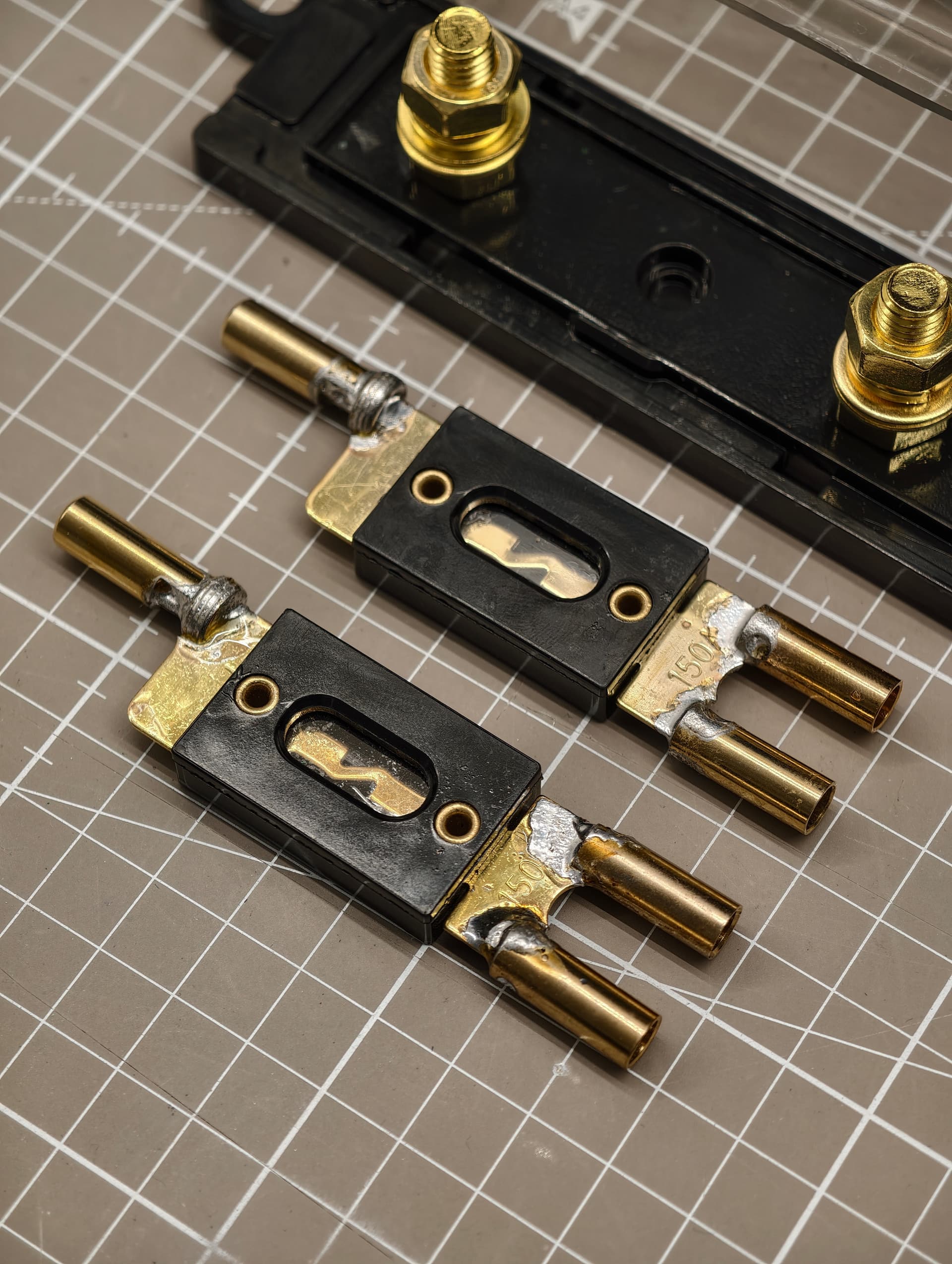
I made compact fuse assemblies with bullet connectors because space was limited. I know people may have opinions on that, so feel free to comment.
So far the pack has been performing really well. Balance was very close from the start, the BMS had almost nothing to correct, the thermal camera didn’t show any suspicious hot spots, and charging/discharging looks good.
I store it around 3.7–3.8 V/cell and charge it before use. The charger is 50.4 V / 15 A.
If anyone here has built similar packs, I’d really appreciate thoughts on the mixed-cell strategy, insulation, structure, fuse setup, waterproof case approach, vibration isolation, or anything else that stands out as a good idea or a bad idea.
I’m not claiming this is the perfect way to do it. I’m just sharing my first serious build and hoping to learn from people who have done more of these.
