DIY Waterproof remote

I also use the SS495A also tested the A1324/5/6 they work about the same I think. Will make a CAD model soon, I want it to bee 3D printable so everyone( including E-skateboard) can have an awesome cheap remote.
I am using the Arduino “servo.writemicrosecons()” to control the ESC.
Where 1000 equals full reverse 1500 idle and 2000 full throttle/ a bit different for the Seaking… Works like a dream.

No fusion 360 i fast and simple, no problem :slight_smile:

The SS495A accepts 10v though. You get 5v of play instead of 2.5 or 1.5. That didn’t make a difference at all? For an Efoil though pretty sure no one is going to need a reverse(just my opinion). Any one else think they will need a reverse? I think it would be more important to make the trigger have lots of play instead of 1/4 movement for all throttle. That was just my concern though.

1 Like

i’m not using the full range on mine as the magnet don’t have an ideal placement to maximize the range.
instead i focused on eliminating all the dynamic seals and reduce the static ones as much as possible, i’m now left with 1 static seal.

I’ll trying to take more detailed pictures tonight or make a nice drawing.

it’s all 3d printed. i’ll waterproof it with a urethane spray or something once it’s final, but for testing, i’ll waterproof it with a condom…:smile:

i’m not worried so much about using the full range as long as the ADC in the transmitter arduino is precise enough…

from the hall sensor to the ESC, i start by: scale the measure Hall effect signal to something like 256-512. and i added a push button inside the remote to be able to send a 0 for ESC calibration).

once that 0-512 reach the receiver, it gets scaled to a 0-180 angle for the ESC…

and let’s face it… we don’t need so many variation in power… 16 or 32 different steps for the power of the motor should be enough.

and for 3d, i’m managing so far with 123d … it’s FREEEEEE! :slight_smile:

1 Like

Mat, Right on!! Your further along than i am :D. I’ll keep at it and see what i come up with. Seems to me you and i have very similar circuit design but for the model you are ahead of me. Cant wait to see what everyone comes up with. Hiorth you have some amazing ideas as well!! I like that rotation around a sensor. Seems smooth!

I am super thrilled about this thread. Great to see that you guys are looking into the waterproof remote. Can’t wait to retire my Ziploc bags :smile: . I too bought a bunch of arduino stuff with radio modules and linear hall sensor several months ago. Didn’t even get a chance open the boxes yet. But happy to help out where I can. Please also think about wireless charging so that we can completely seal these things up. Good to have parallel experiments and I am sure we will find ways to merge these efforts down the road. Thanks!

1 Like

as promised!
on the first picture are my test pieces:

the part 1 is the trigger, it contains 2 magnets together. i could be one long instead… not sure where to find them though… the longer the magnet, the longer the range of motion of the trigger.

the sensor is mounted on part 3, it’s the “electronic chassis”, part 3 also hold the boards (arduino and transmitter), the push button to make the 0, and the reed interruptor to turn it on with a magnet from the outside.

finally part 2 is the top half of the housing. it’s at least 2mm thick everywhere .
as part 1 has magnets attached to it, if you add a magnet attached to the part 2 mounted to repulse the ones from 1, you get a “spring” that bring back the throttle at 0!, no jamming, bad spring or any other issue.

on the second picture is the whole remote disassembled.
yes it has a ugly 9v battery not rechargeable, but i needed to voltage to get the power to penetrate water. if your receiver is at the surface, the guts of any USB power bank will do the trick, and you can even use contractors going through the casing to recharge it from the outside, completely fill the inside with grease a have no fear of water :slight_smile:

that “part 2” has the recoil magnet assembled.
the part at the bottom is the second half of the casing, so the only seal needed is between the top and bottom half.

the green painter tape slides up and down the body and hold the on/off magnet.

note, when using 433mhz transmitter, you can use a 1/4 wave coil loaded antenna and it fits nicely inside… but again, if your receiver is above the surface, the signal strength is not a problem at all…

5 Likes

Nice job Mokra!
Keep on plugging away…

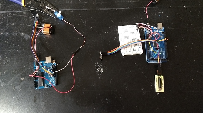
Hi All - I’ve been lurking for some time and figured now was a good time to join the conversation. I’ve been planning and acquiring some parts for a month or so and have a pretty good solution for a DIY remote control. It may have been done already, but I haven’t seen it yet. There are magnetic potentiometers which are perfect to put inside a DIY controller. High-Temp Resistance Linear Potentiometers | HotPot .

Essentially you put the magnetopots behind a waterproof barrier and a small neodymium magnet on the outside as a slider. I’ve successfully bench tested it as an ESC / servo controller using two arduino’s setup with wireless chips.

Here’s a pic of the setup and a video of the testing. https://www.youtube.com/watch?v=MsclCpbj_3w

Still need to polish the arduino code to have all the safety aspects covered, but it is relatively simple stuff.

Now I just need to design a controller handle to put it all in, including a spring loaded trigger.

Cheers,

Justin

2 Likes

Hi Justin,
Great to hear that your winning! I’ve also gone down the arduino rabbithole with some success… Sort of? I’ve discovered I’m quite the hacker but alas I can’t get my code to work properly…would you be willing to share your code? Happy to provide all my CAD files as a fair and open swap.

Aaron

note: i’m using 433 or 315 MHz transmitters, it will be different for Bluetooth or wifi…

tx:

#include <RH_ASK.h>
#include <SPI.h> // Not actually used but needed to compile
RH_ASK driver(5000, 0, 1 );
int potPin = A3;
int potPosition = 0;
int potPosition1 = 0;

void setup() {
Serial.begin(9600);
if (!driver.init())
Serial.println(“init failed”);
}

void loop() {
potPosition1 = analogRead(potPin);
//potPosition = map(potPosition1, 245, 635, 0, 255);
potPosition = map(potPosition1, 0, 640, 0, 255);
uint8_t values[1];
values[0]=(uint8_t) potPosition;
Serial.print("PP: ");
Serial.print(potPosition);
Serial.print("PP1: ");
Serial.println(potPosition1);
driver.send(values, 1);
driver.waitPacketSent();
delay(2);
}

RX:
#include <RH_ASK.h>
#include <SPI.h> // Not actually used but needed to compile
#include <SoftwareServo.h>
RH_ASK driver(5000, 0, 1 );
SoftwareServo esc;
int SERVO_LOW = 0;
int SERVO_HIGH = 180;
int c1,c2,c3;
int v1=0;
int vs=0;
int vn=0;
unsigned long lastM;
unsigned long currentT;

void setup() {
esc.attach(3);
Serial.begin(9600);
if (!driver.init())
Serial.println(“init failed”);
}

void loop() {
uint8_t buf[4];
uint8_t buflen = sizeof(buf);
esc.refresh();
if (driver.recv(buf, &buflen))
{
c1 = buf[0];
lastM = millis();
v1 = map(c1, 0, 255, SERVO_LOW, SERVO_HIGH);
}
vs = esc.read();
if( v1-vs > 2 || v1-vs<-2)
{
vn = vs + 0.5*(v1-vs);
esc.write(vn);
esc.refresh();
}
delay(50);
currentT = millis();
if((unsigned long)(currentT-lastM) > 1000 && vs!= 0)
{
esc.write(0);
esc.refresh();
v1=0;
vn=0;
}
Serial.print(" v1:");
Serial.print(v1);
Serial.print(" vs:");
Serial.print(vs);
Serial.print(" vn:");
Serial.print(vn);
Serial.print(" currentT:");
Serial.print(currentT);
Serial.print(" lastM:");
Serial.println(lastM);
Serial.print(" c1:");
Serial.println(c1);
}

the TX is straight forward: with the scaling explained above
the RX is messy…
the part with VS was an attempt a removing servo jitter (i was testing with a servo to avoid issues with the ESC…
the part with currentT is the failsafe… it counts the time since last signal received, and if it’s more than 1 second, it puts the ESC to 0…

all the debugging serial print are still in… i

1 Like

Will do - let me package it up and I’ll respond back.

@Hiorth how did your hall sensor trigger work out? I’ve ordered some parts to build a similar setup. Any tips of magnet strength/size etc and position relative to the sensor?

@Justin thanks for showing us the magnetopots. They look ideal. How have they been working for you? How does it work with the magnet through 2-3mm or plastic?

What length looks to work best? I’m thinking 25mm set in a curve to work with a rotating trigger action.

Works grate! i use cheap magnets from ebay, they are round 10mm*3mm. i have also orderd several smaller magnets.

in my setup you can rotate the sensor to calibrate with the trigger. I think this halleffect solution is the best:P

started 3D drawing today.:slight_smile:

I got 25mm and it seems to be a perfect length for a trigger. They aren’t flexible so I’m not sure what your plan is for “setting in a curve”. The construction seems like it is a steal bearing riding back and forth in a rigid plastic slot. I tested through about 2mm of plastic and it held fine. You can always get a stronger magnet if not!

I wanted to get something out before the weekend - here’s my code, references to how to setup and some pictures.

Please note I’ve only bench tested and it’s worked great so far. I want to add some safety features!

I will also note that if the magnet disengages, the magnetopot / speed becomes erratic as the ball rolls freely inside the slot!

Thanks for the feedback @Justin. For some reason I thought the magentopots were flexible which would have been ideal.

That’s unfortunate that if the magnet disengages that the resistance can be erratic due to the ball rolling around. Not a very good failsafe if the mechanical magnet position fails in remote.

I’ll do some tests when mine arrive none the less.

@Hiorth feel free to share 3D designs for hall sensor setup :slight_smile: although I’m still a few week away from testing yet.

@g.gregory8 will share when tested. Will 3d print new design today or tomorrow.

Have any one found a good ON/OFF switch. I would prefer not to use a Magnetic read switch. I want the type you can press one time to turn and one time to turn off. Same type found in waterproof Flashlights. It has to be waterproof and small.

water proof push buttons seems to generally be quite big…
i found some small but not waterproof ones and i put them below a small window (1/2 in by 1/2 inch) in the casing.
finally you can "mold"silicon in it to make the casing waterproof.

the silicon by itself can be a bit weak and tear (i guess the brand depends a lot) but you can also shape a small piece of extensible fabric on a small dome shape, silicon the fabric on one side, remove the same as silicone on the other side… once cured it will keep its shape. finally you can glue it to the casing over a regular button…

but in the end, i went back to reed switch on a battery wire, much smaller and less waterproofing issues…

Can’t wait for this waterproof remote you guys are working on. Am going out now and here is today’s solution. The ziplock bags popp on hard crashes.

17 Likes