doesn’t the pressure switch have 2 screws? one for vacuum level and one for hysteresis?
There’s a screw in there?  I thought that was an inlet vent for some kind of closed system.
mine has 2… if it turns, try it!
1 Like
Guess what came in  I knew it was going to be big, but wow. Doesn’t really look like it in this picture, bit it’s significantly larger in diameter than the beer can.
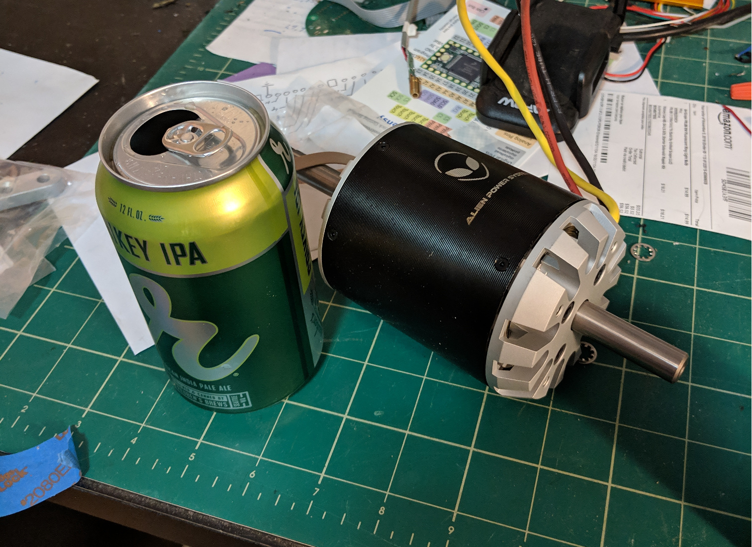
So assuming I’m going to run it in fresh water Is there consensus on the best bearings to run? Pointer to parts?
Also I read that someone replaced the driveshaft with a titanium shaft. A bit exotic for my tastes, but does the driveshaft rust if not replaced? I was able to find 12mm stainless but I’d rather not replace the shaft unless absolutely necessary.
I’m also going to epoxy dip/vacuum both the rotor and the can - recommendations on the best epoxy to use? I think the stuff I have is too thick to do the job without causing problems.
Thank you for recommendations.
Are you building your drive unit based on one done on this site (PacificMeister, Hiorth, etc) or are you starting from scratch?
Probably from scratch. I’ll need to get the driver and the mast in stock before I start.
No doubt I’ll be using those builds as reference.
I base my build on Mat, that’s why I went with his idea of replacing the shaft with a shorter titanium one and using open stainless steel bearings.
The motivation was that open bearings will be easier to lubricate and won’t have dust and water trapped inside. I think it doesn’t matter what specific bearings you get, as long as they are stainless and of right size.
As for the shaft, as you probably realized, the stock one is way too long so you need to shorten it anyway - it is almost easier to directly replacing it with a 10cm titanium shaft that needs no cutting, just a circlip groove. At least you are on the safe side with corrosion, I put the motor in a bucket of tap water for around 24h to dissolve some PVA and all screws that where left in and also the can itself corroded, so I wouldn’t want an integral part of the motor to be normal steel. You need to disassemble the motor anyway, from there on it is just 2 set screws to swap the shaft.
1 Like
Exactly what @Benjo said! and titanium sounds cool and is not expensive for the shaft, much easier to machine too and a bit lighter
One thing you want to be carefully with when applying the epoxy is that the gap between outside of stator and inside of rotor is not that big… it’s easy to remove thickness on the stator, not so much on the rotor, so keep it thin there.
I dunno if it’s specially adapted, but surfboard epoxy does the trick.
1 Like
Where did you source the titanium shaft?
and it’s already the right length …
1 Like
Ok, final proof of concept on the hard cutoff is successful. It can easily make it through 0.125" plastic and probably 0.150 - I doubt a pelican case is much thicker than that.
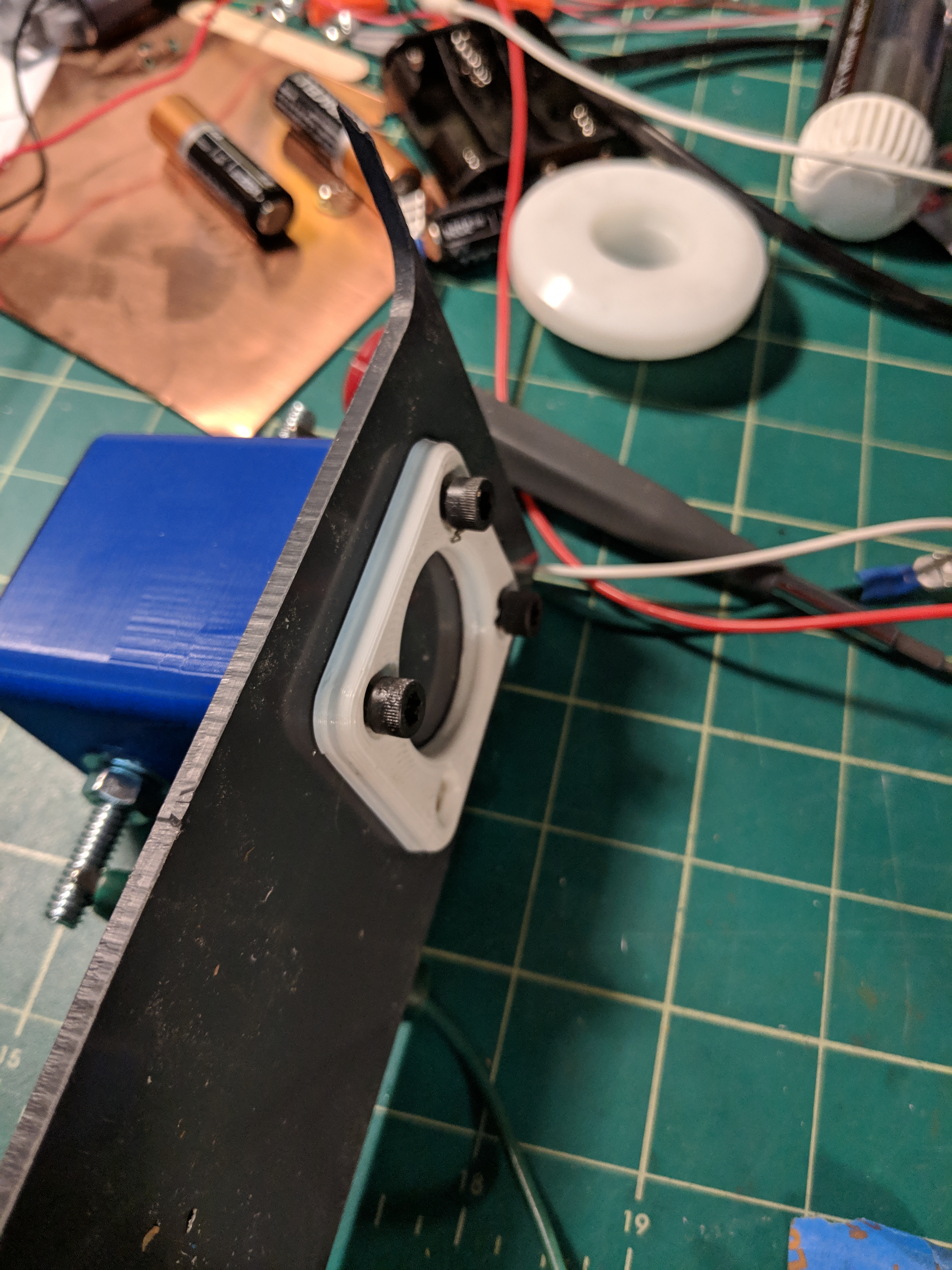
This image shows the cutoff attached to a sheet of plastic. Notice the adjustment screw on the bottom - this defines how far the magnet in the cutoff is from the plastic. I set it to 0.1".

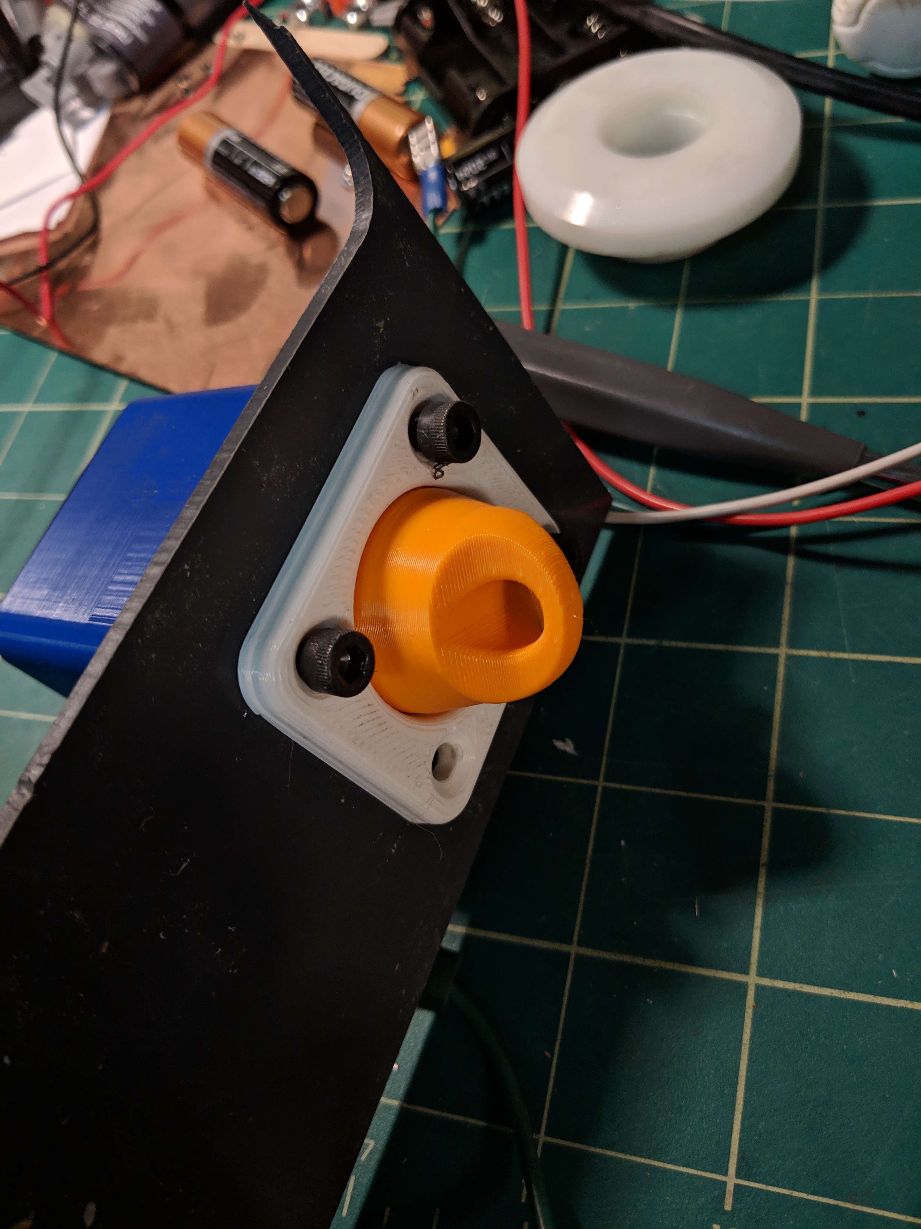
This image shows what will be the outside of the Pelican. The white piece bolts through the case into the cutoff (there are 0-rings around the screw holes in the cutoff housing). The final rev will have flathead screws. I didn’t have any in stock. The white piece is the target and the orange is the magnet that you tether to your body.
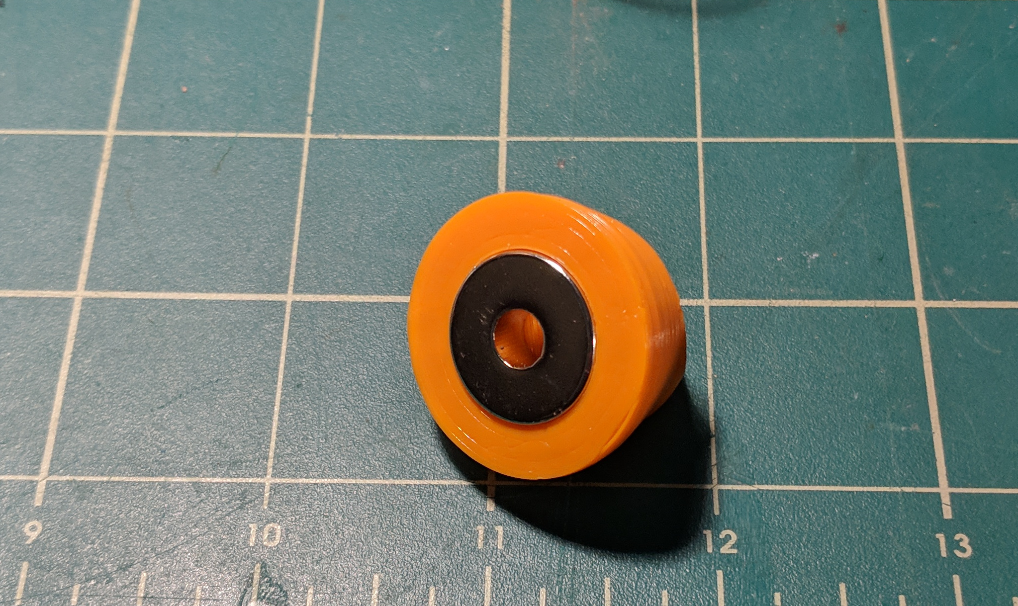
Here’s the orange magnet from the other side
I haven’t quite finished with the anti-spark, but I have the parts in stock and I know how I’m going to do it.
But placing the magnet in position makes the connection and it all works!! A couple of small changes to the model, print the final housing, add anti-spark and ready for full power testing.
Before I mount it in the case I need to get the batteries and the receiver circuit in there so it doesn’t interfere with any of them.
Unfortunately the rest of the day I spent down a rabbit hole trying to make a device for the vacuum pump that extracts the oil mist before it goes out into the shop.
3 Likes
Those of you who know me (that’s none of you yet - it’s kind of a rhetorical statement) know that I’m super-easily distracted by shiny things.
And it bothered me that the stupid vacuum pump was filling my shop with oil mist, so I decided to fix it. Of course instead of just buying a filter ($80!) I decided to do it myself (a day and a half).
First step was to get this foam oil separator filter.
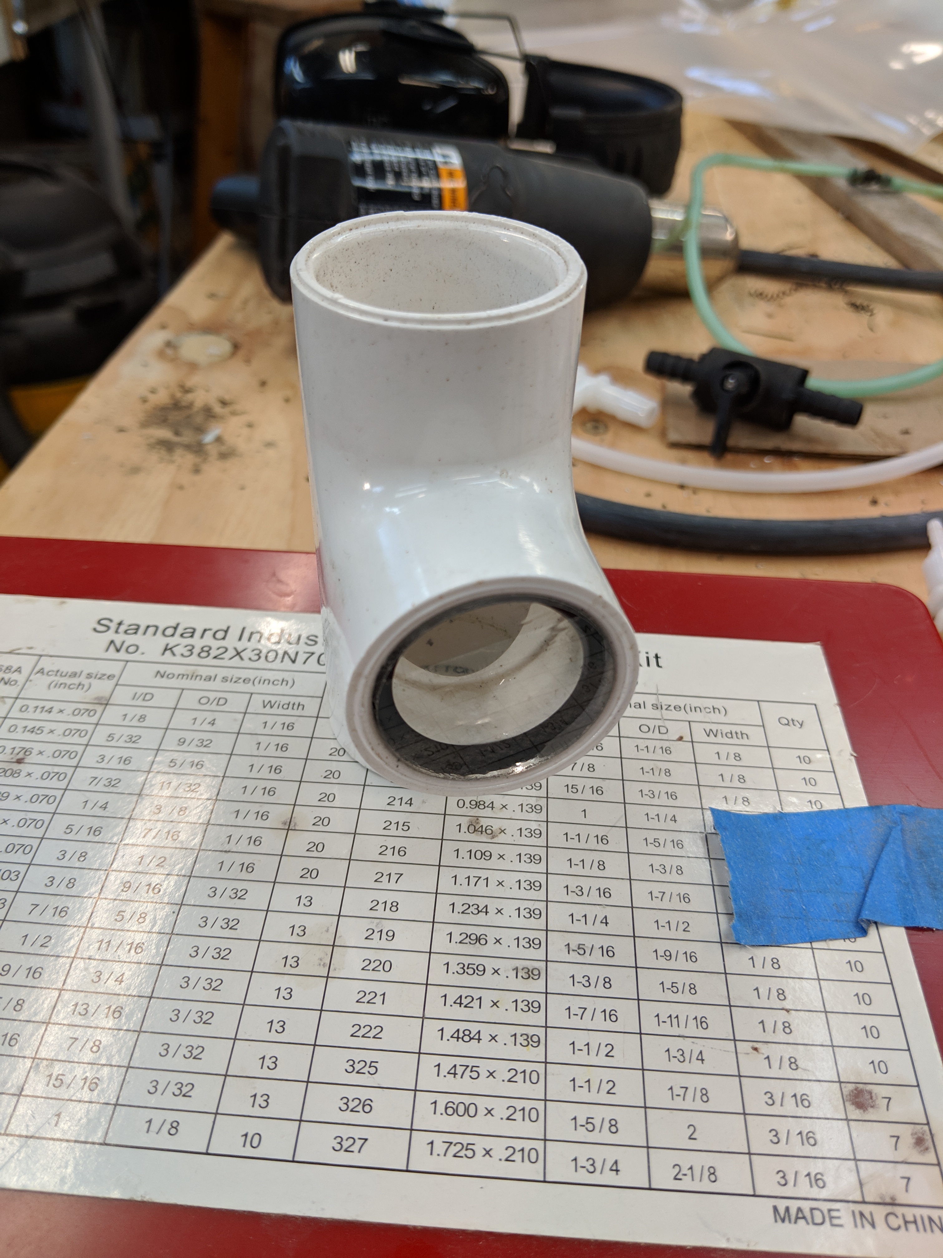
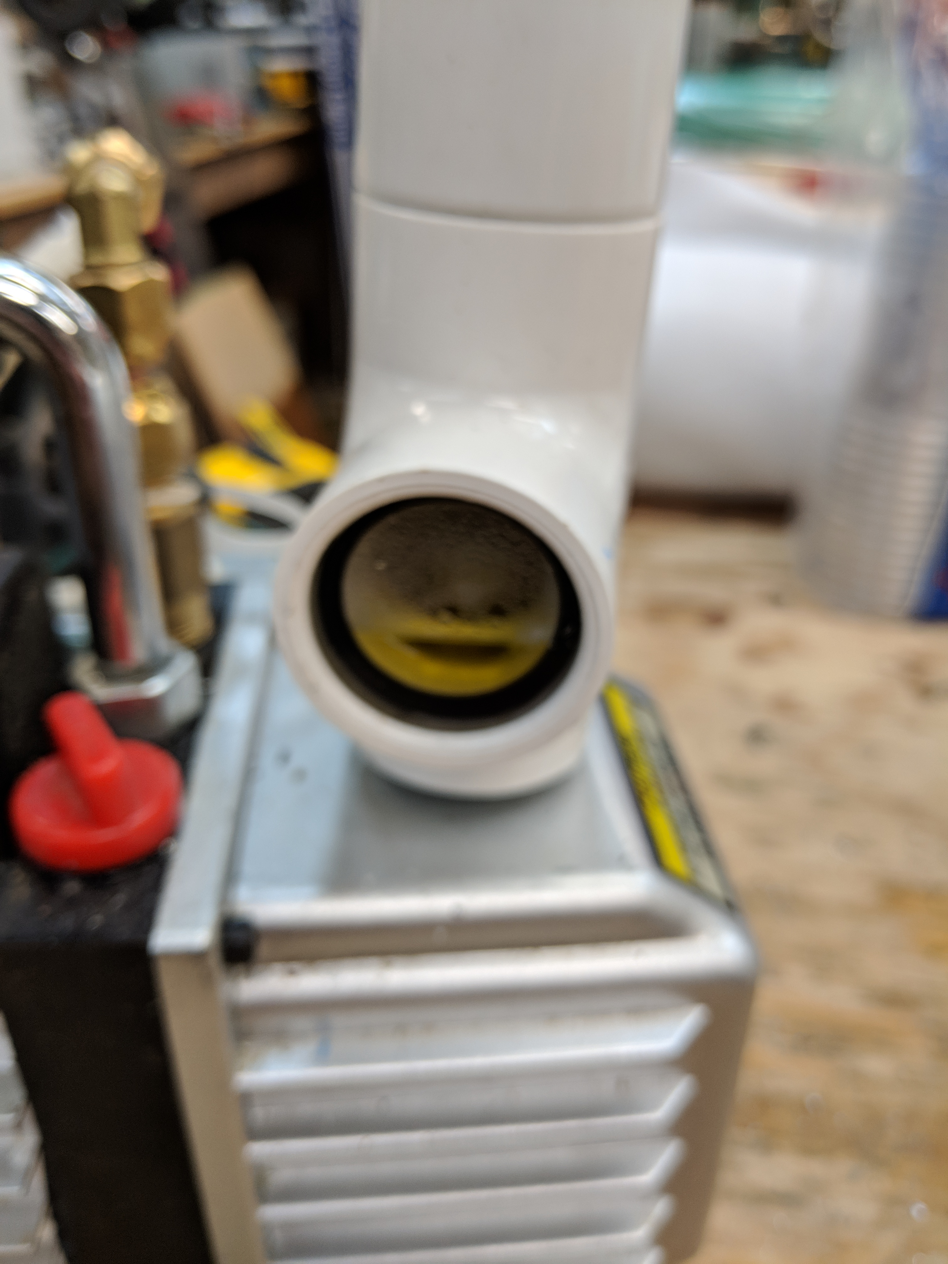
for a housing I cobbled together some 1 1/2" PVC pipe parts. Since I happened to have a T handy I decided it would be cool to have a view port so I could see when the thing filled up with oil and needed to be drained/poured back into the pump. So using this super-sketch technique here:
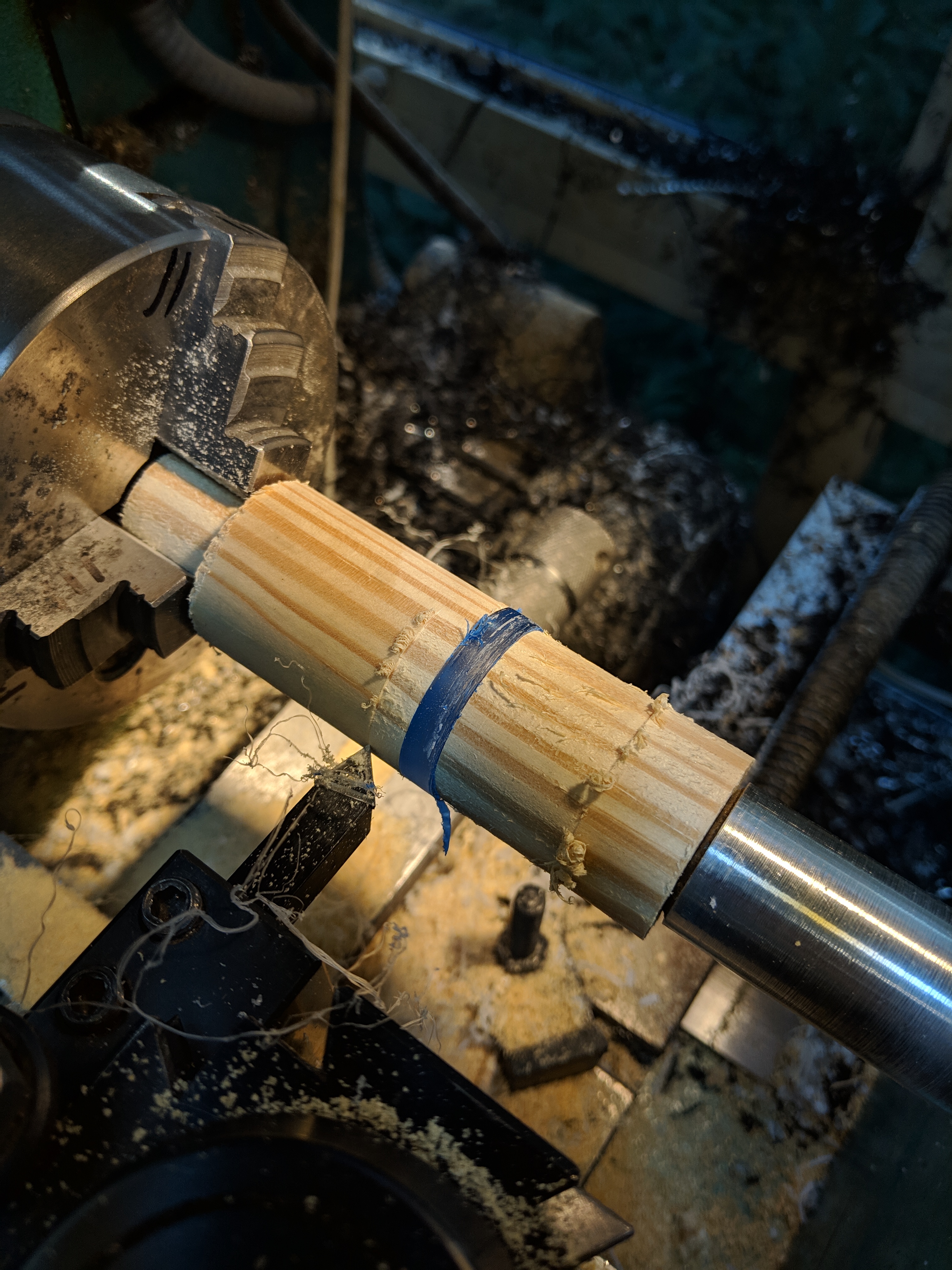
I turned a piece of plexi to the proper diameter and cut a slot for a rubber gasket, then pressed it into the pipe
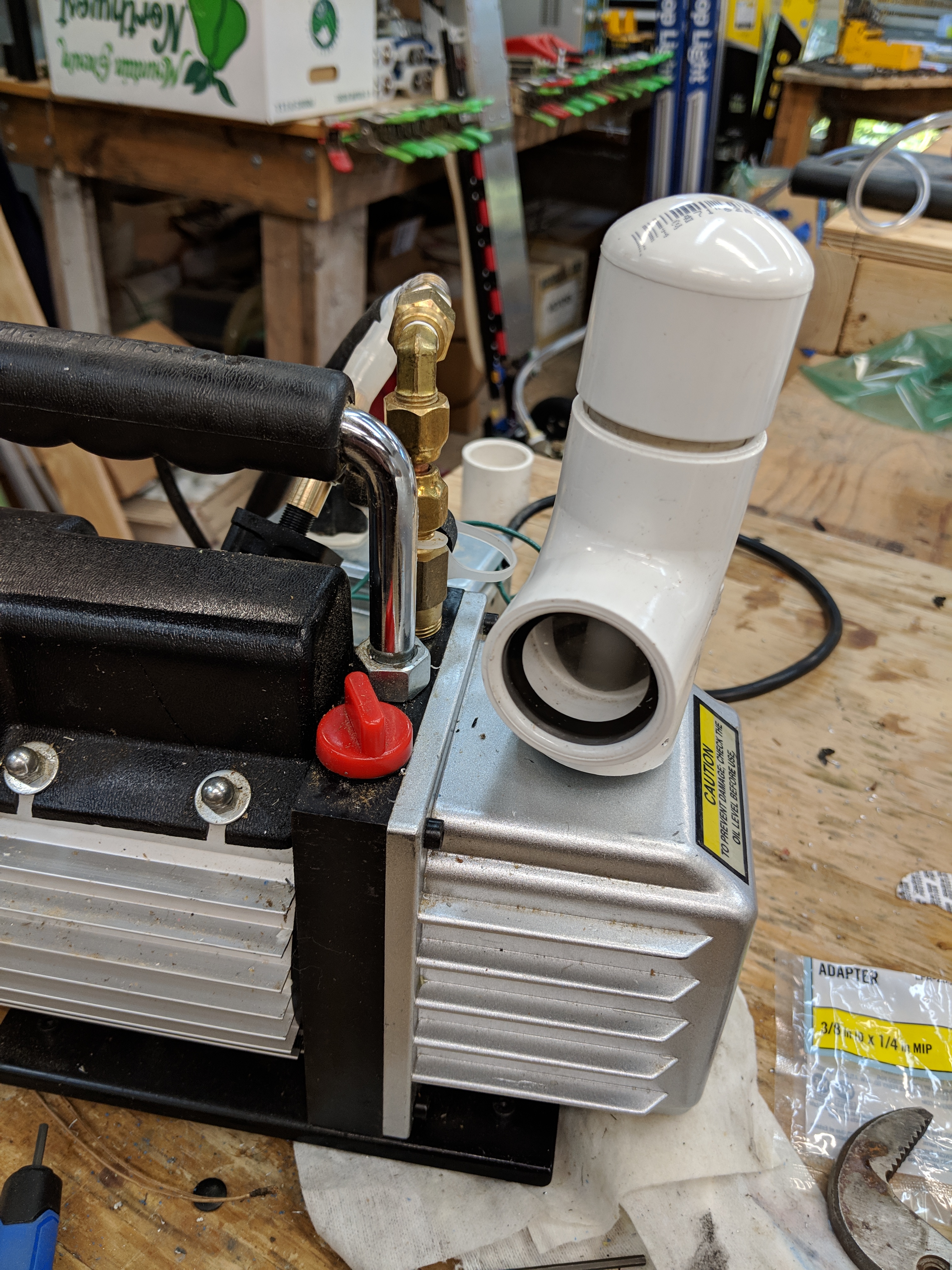
I then turned down a piece I could thread into the pump and another piece to hold the filter in place. (if you look through the view port you can barely see the white pipe that goes up. You can’t see the filter - it’s above the window)
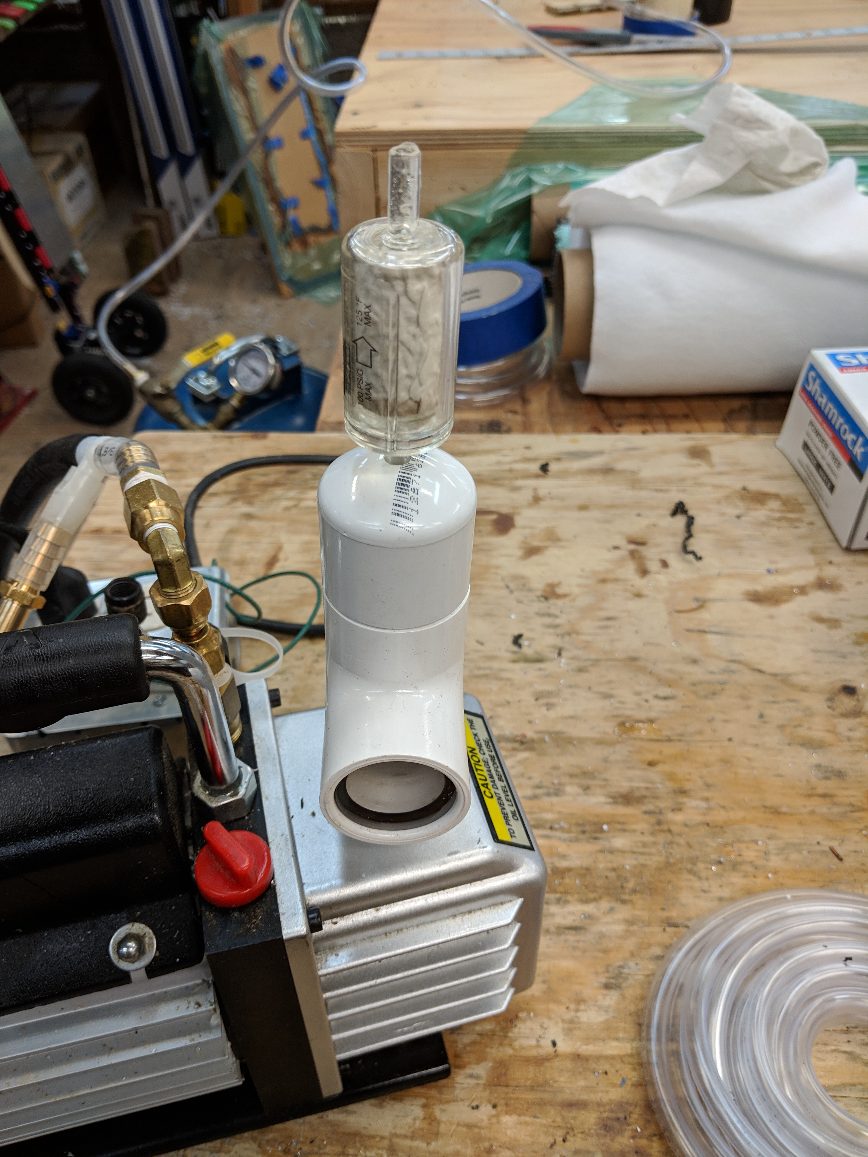
That worked really well and the mist problem is totally solved. But I happened to have a paper filter from an earlier failed attempt at fixing this problem, so I cleaned it up (hence the water droplets in the outlet pipe) and stuck it on top for 2-part filtration.
I had originally planned to run it through a carbon filter from a Nissan, but what I got was a carbon filter housing with no actual carbon, so that was useless.
Anyway, now back to Carbon Fiber layup.
UPDATE
good thing I put the sight glass in there
This is after maybe an hour and a half of cycling.
An obvious upgrade would be to put a tiny flapper valve on the bottom so that when the compressor turned off the oil would drain back down into the sump.
3 Likes
I know what you mean. Stay on task. Focus.
1 Like
Trying to get it perfect for yourself is fine for a hobby project, especially invested in tools and safety.
It will pay off in health and motivation to go out in the shop without the oil mist. I couldnt really do much in the shop the last week because of not taking my time before 
In any case a useful project, thanks for sharing it.
1 Like
I’m playing around with a refrigerator compressor tonight - I think I can use the above compressor to empty the reservoir and draw down the form and then switch to the refrigerator compressor to maintain vacuum.
The very first time I tried to use that 24x24" vacuum bag it was too small, so I’m going to upgrade, probably not screw around and go for a 24x48".
In the meantime I went back to the old system of using plastic sheeting and I’m just too lazy to figure out how to get a perfect seal so I’m going to live with a slightly leaky form. In terms of outcome I don’t think it matters at all.
UPDATE: Well, that was a bust. The compressor is seized. Imagine that, sitting in my carport for only 10 years and the dumb thing doesn’t work. Youtube says there’s 2 ways to fix it (aside from cutting the case open and rebuilding it) hit it with a hammer, which I tried; and blasting it with 240V for a second, which will be my last ditch effort.
But not tonight.
Hello doug! I know Im a few days late haha but check out my build post! You will find instructions on how to waterproof your motor as well as the right products to do it! It is based on how mat proceeded!!
for the compressor seized, i have tried to put the WD40 in it , let it rest a bit and apply air pressure in order to move the piston (if it has one) ?
1 Like
Despite a very frustrating beginning to the day I managed to get the remote to drive the motor via the new Swordfish ESC. Here’s a Video!. Astute observers will note that I’m running this motor via a Husqvarna weedeater battery.
It was a long and frustrating day - first the Swordfish didn’t work at all, then I accidentally shorted the shit out of one of my VESC’s and probably destroyed it. Then I disconnected the swordfish and let the wire drop down and of course it shorted again. Like what are the chances if you let one end of your positive lead drop off the edge of the desk of it falling directly onto the negative lead?!? 100% apparently.
Then I took a nap.
After that I learned (thanks to HyproFoil) that the swordfish doesn’t provide 5V to the receiver and you need to get a thing called a UBEC (Universal Battery Elimination Circuit). Where I come from we call them switching regulators.
Anyways, you have to source 5V externally to the receiver but you also need to feed that 5V back into the Swordfish or it won’t arm.
Once I got that figured out I was able to use this arduino library to drive the motor around and it seems pretty reliable. There’s a bunch more functionality to this library that I haven’t really looked into.
Then it was just a matter of writing a bit of code that took the output value from the remote (0-100) and convert it to the proper speed values for the library.
I know what you’re asking, “But Doug, where the hell did that magic remote come from? You never talked about it even though you promised!”
Well, I’ve been busy. But let me give you the quickest of rundowns on it.
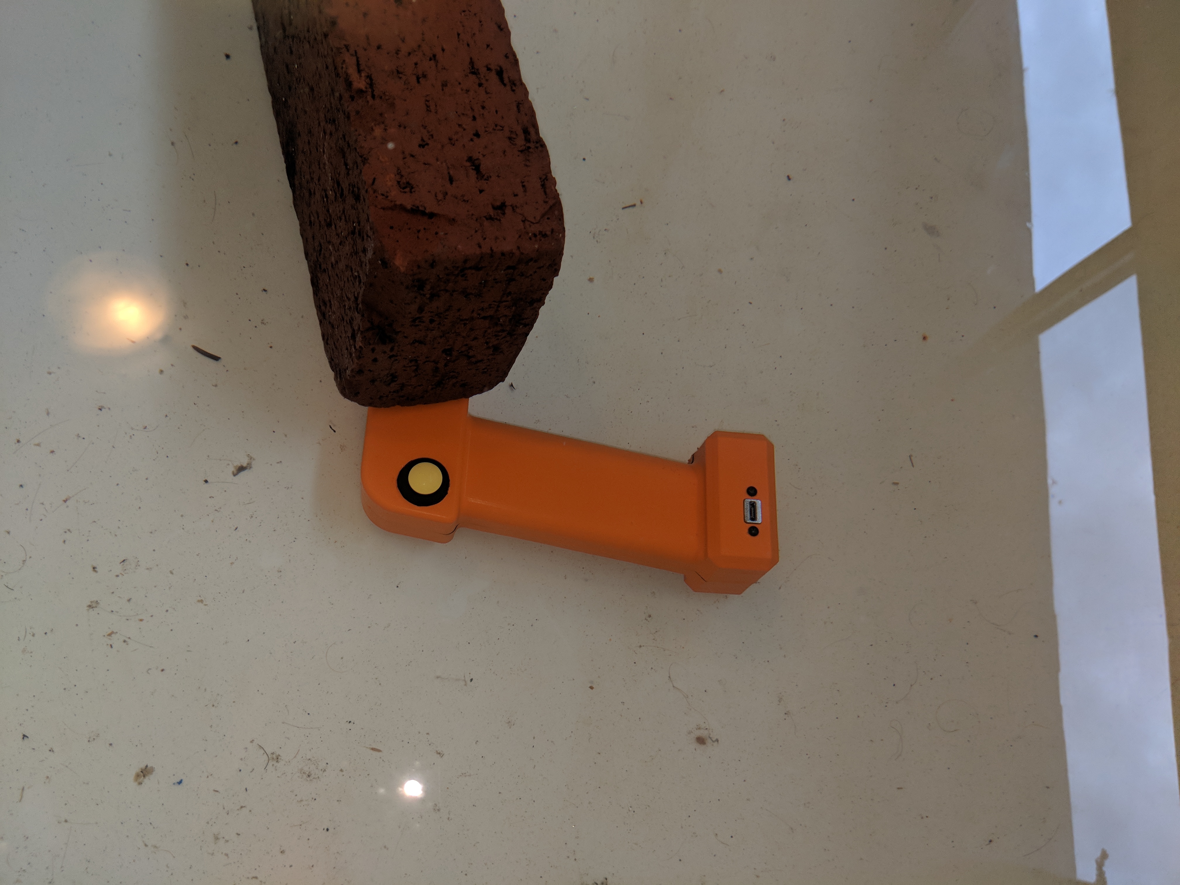
I had a great idea. I thought, what if I 3D print a PLA housing and then coat it inside and out in plasti-dip?
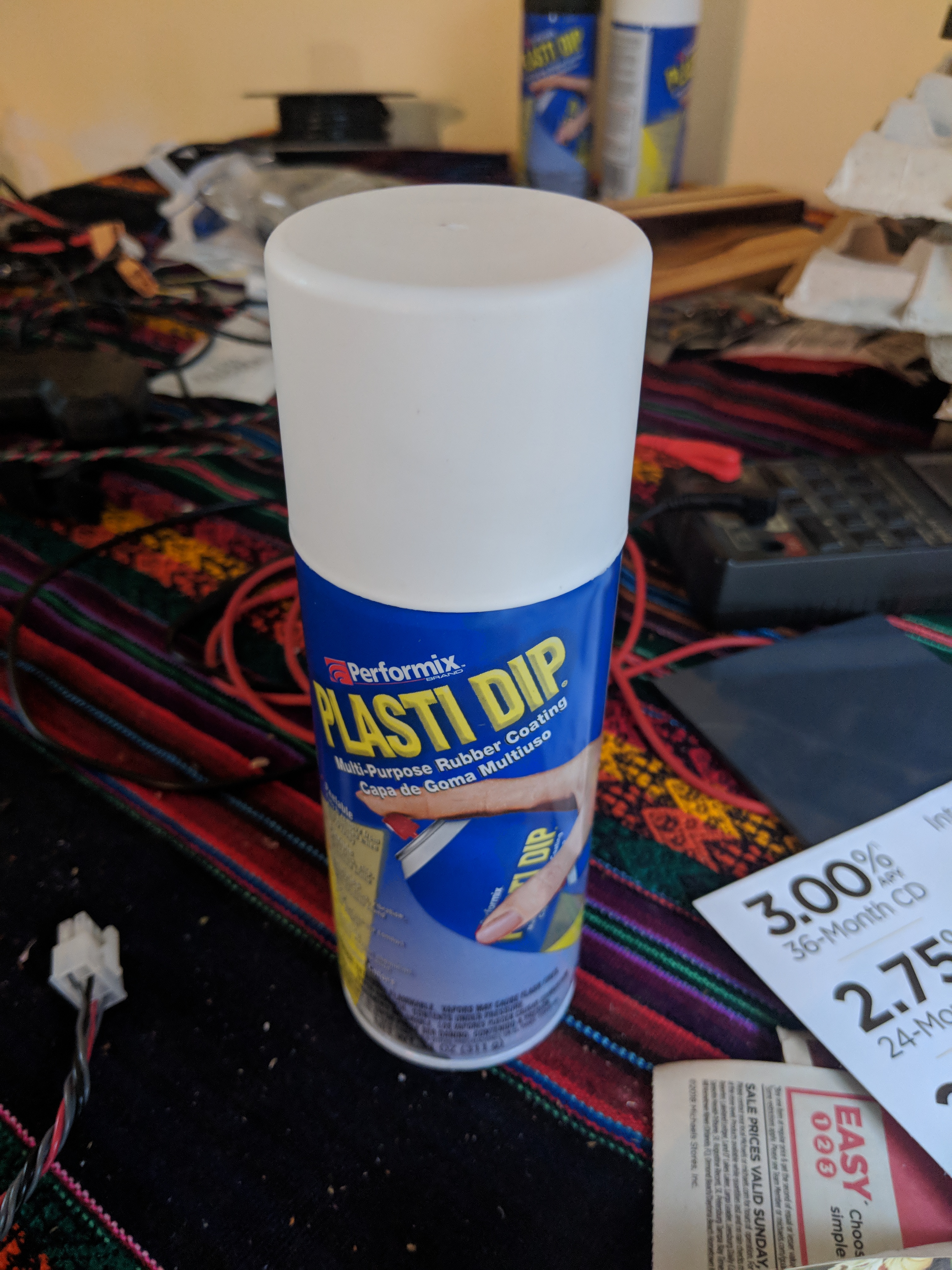
So I tried it. I just made a housing with no innards and sprayed it inside and out. Then I screwed it together and put it under a brick in my bathtub for a day.

And it almost worked! There were just a few drops of water inside the case. I still think with a bit of added design thought this could be a great solution.
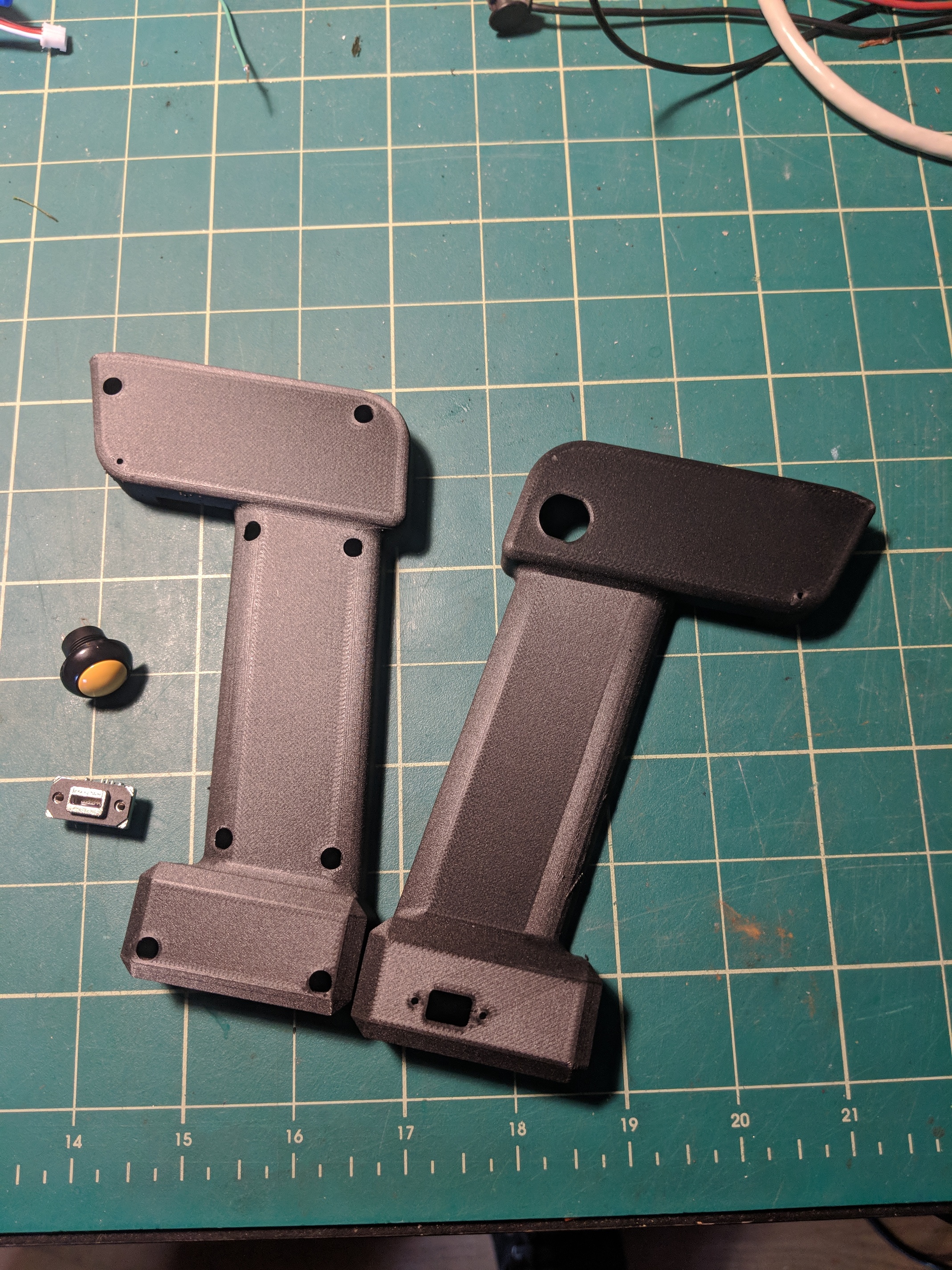
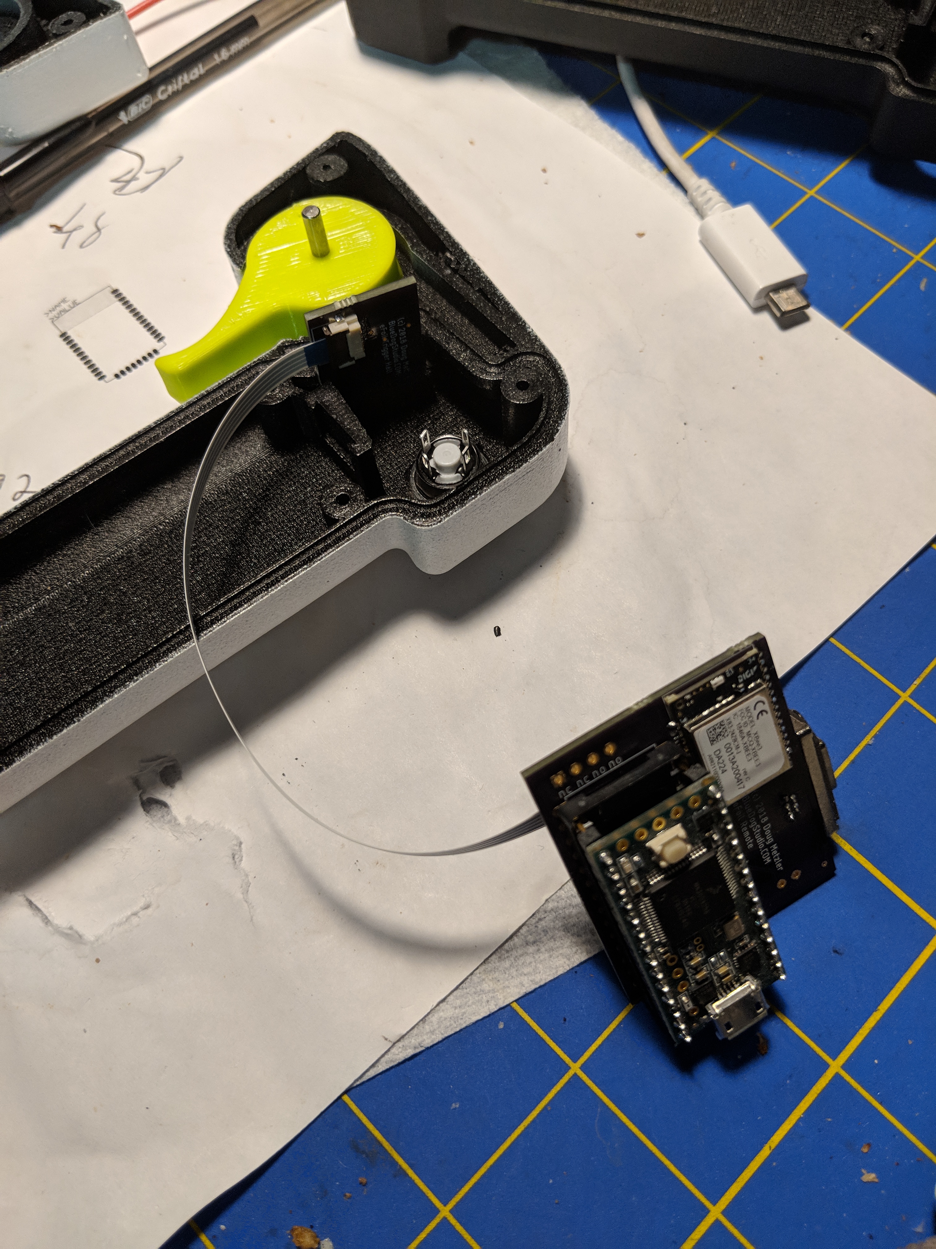
But I wanted total waterproof so I decided to design a remote from the ground up to have a wet space and a dry space. the wet space would contain the trigger with an embedded magnet:
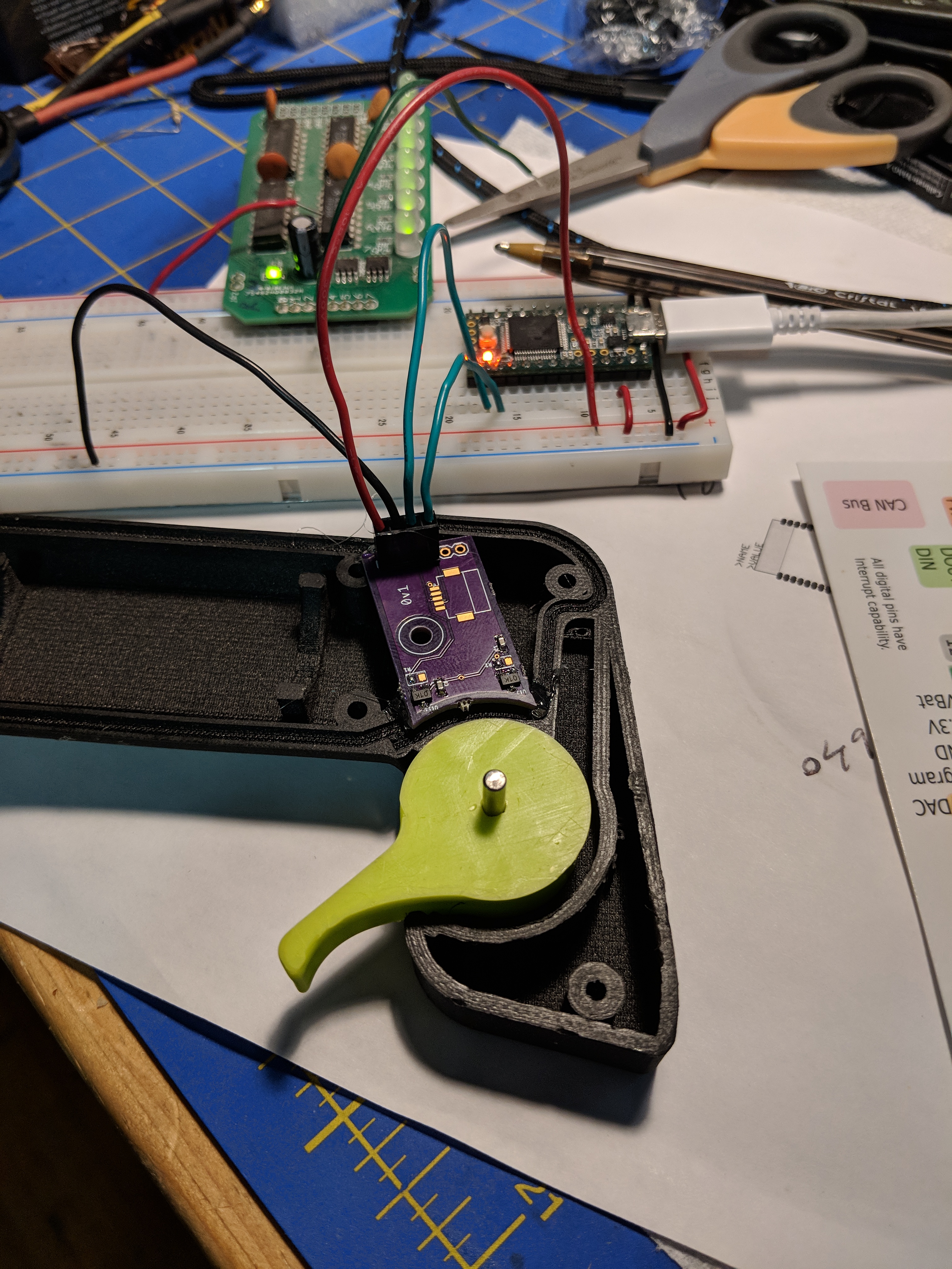
and the dry space would contain the battery, the motherboard and a daughterboard with some hall sensors on it. This is not the final daughterboard (there’ll be a picture of that later) but it does show the 2 analog hall sensors at each end of the magnet’s travel.
If you look really closely at the picture you’ll notice that there is a channel for a rubber gasket around the section that will contain the electronics.
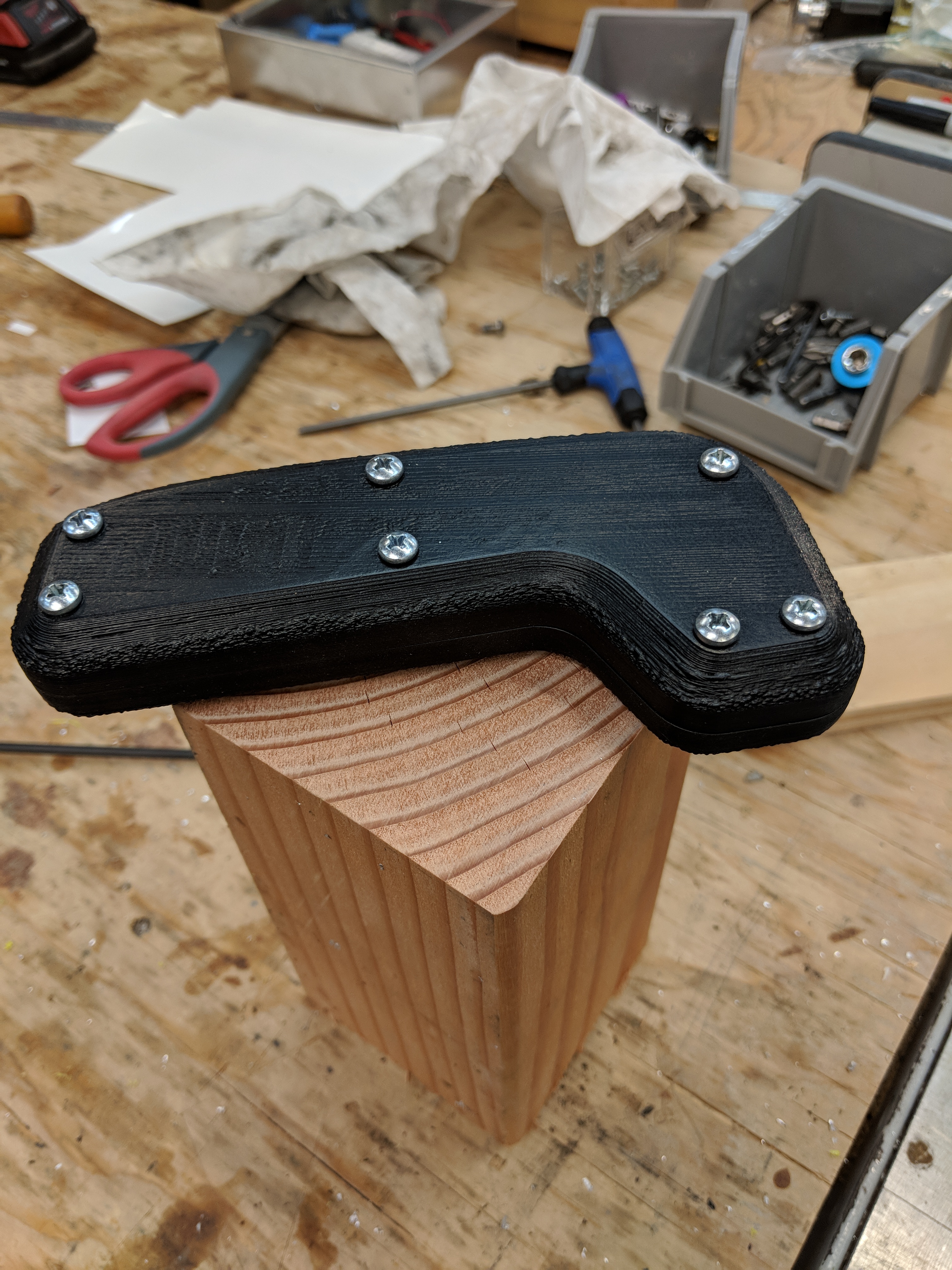
A couple of iterations on the case design later and I had this:
(note below that when you do your final rubber seal before you close it up you want to coat the rubber with Dow4)
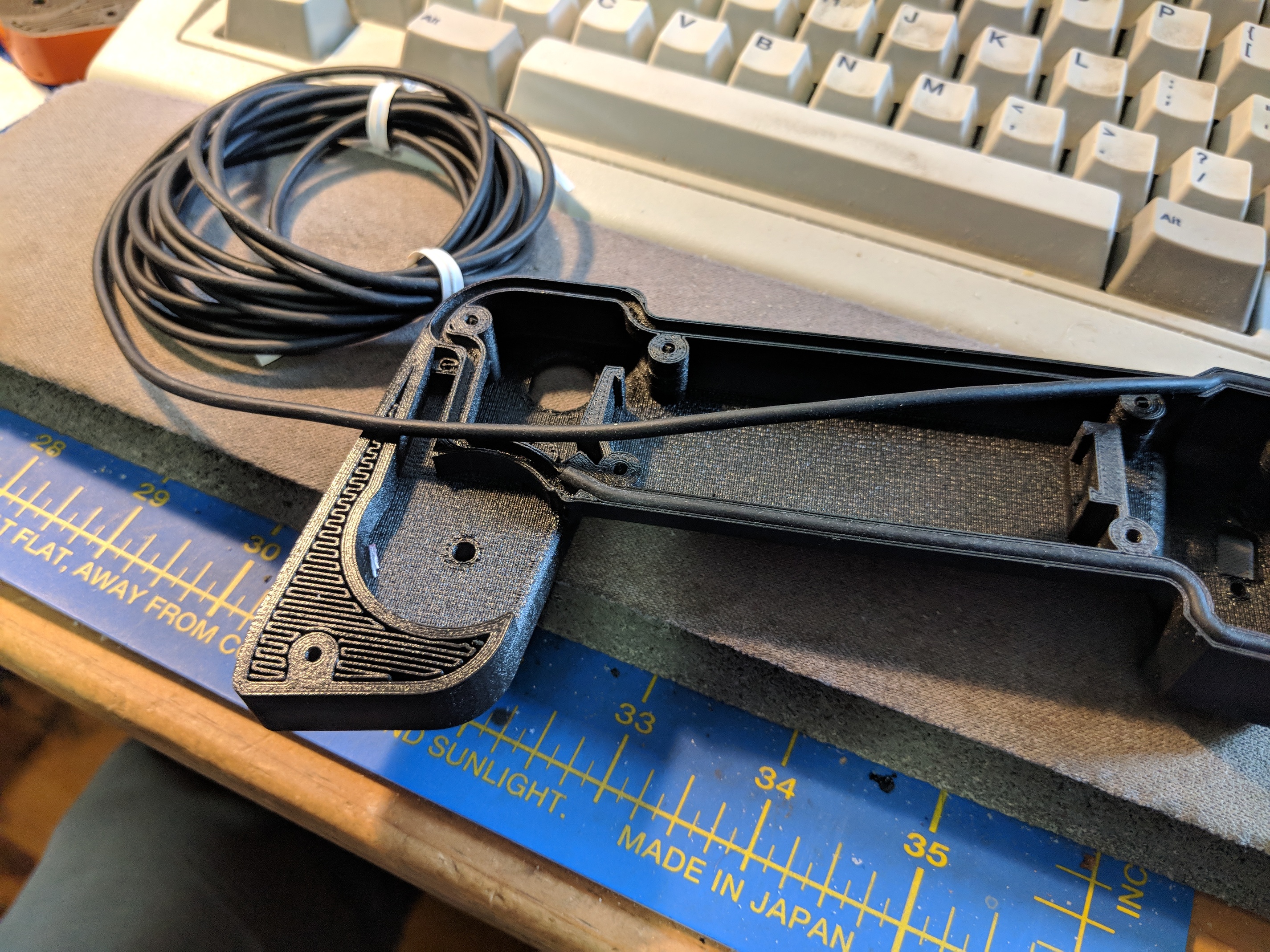
(the curcuit board here is prototype - the final is a bit more sleek)
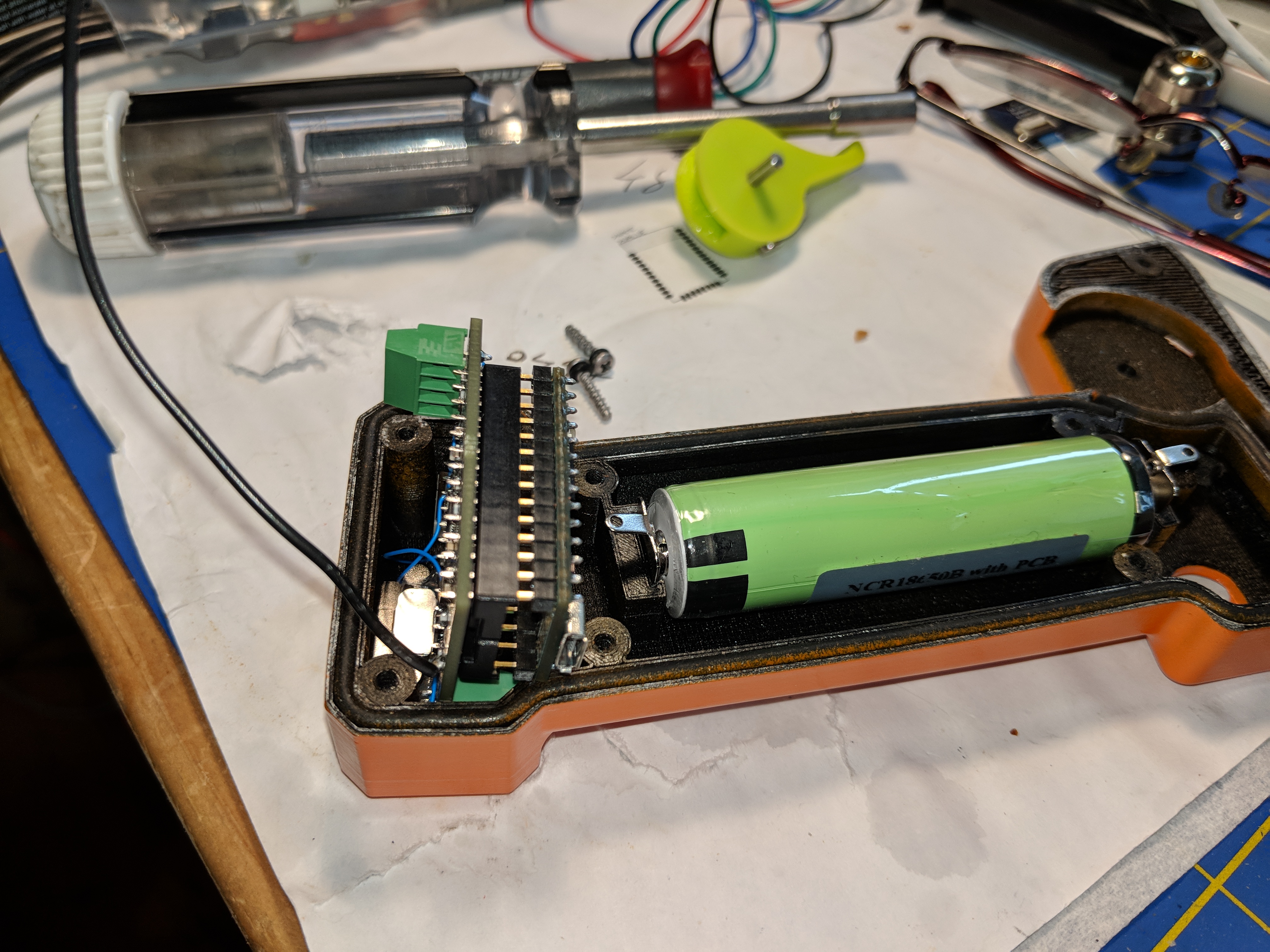
As much as I liked the Plasti-dip solution I just really didn’t like the way it felt when I held it in my hand. So I went back to standard rattle-can on the outside, and on the inside I sealed it with some sort of spray shellac. I couldn’t seal the outside with shellac because weirdly when it gets water drops on it it discolors:
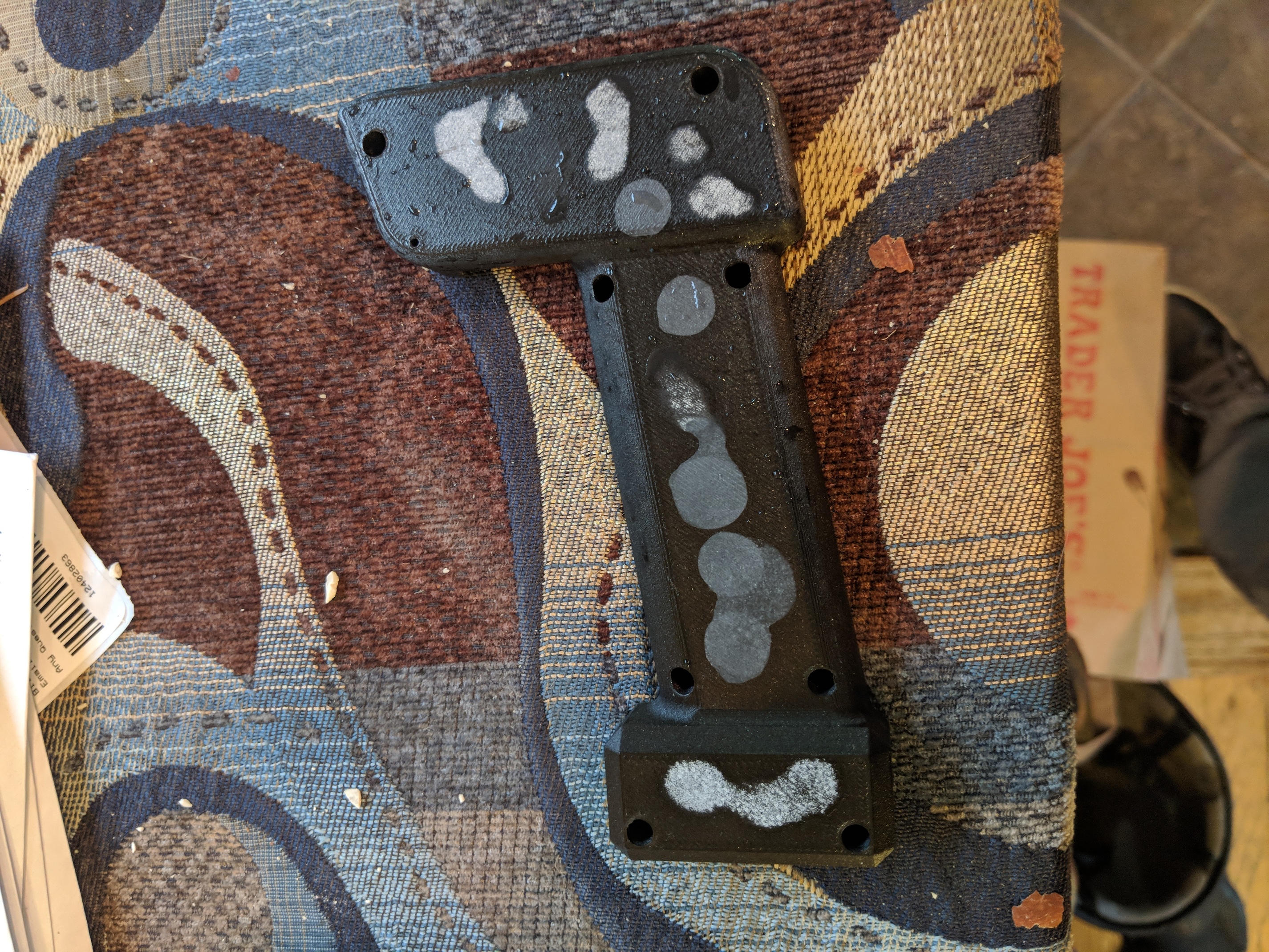
Then I bolted in all the pieces-parts and tossed it back in the tub. It was almost perfect. Just a slight drop of water inside, which is probably fine because daily use won’t really entail total submersion for long periods of time.
The yellow button is the power button. Click to turn on, click and hold to turn off. The thing on the bottom is the USB charge port. And those are the only 2 openings in the whole thing.
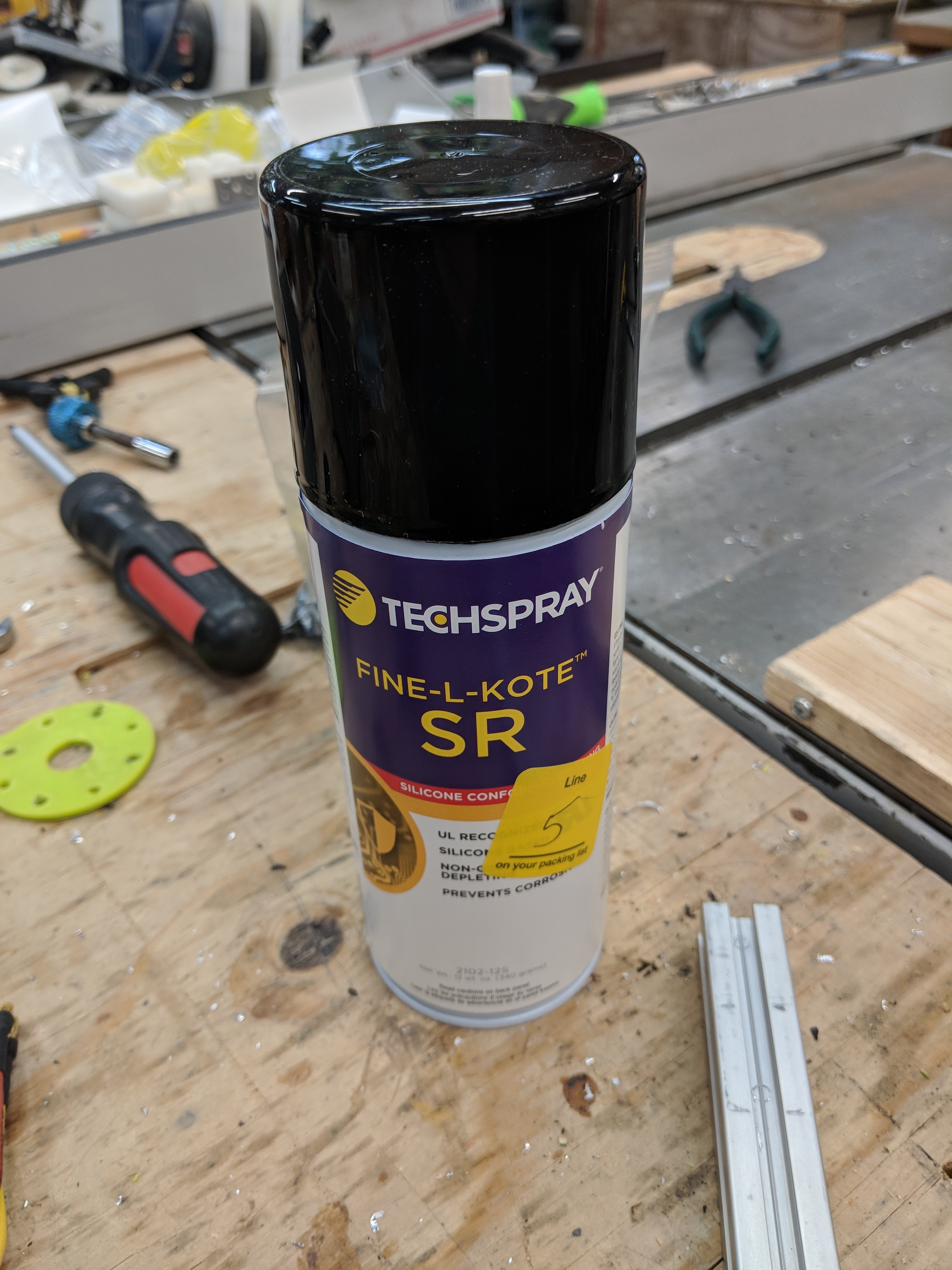
Before I take this thing out to the lake I need to take it apart and spray conformal coating on the circuit boards
The circuit consists of an XBee3, a Teensy 3.2, a LiPo charge chip and a couple of components to facilitate the click-on click-off. The XBee allows for 2-way communication between the remote and the rest of the system, so I can report battery state and such to the display subsystem.
Things I will do differently in the next rev:
- put haptic feedback on the circuit board so I can buzz when the thing turns on and buzz again when the thing turns off, buzz when it connects, buzz when the primary battery is low, etc.
- the trigger is probably too difficult a method for me to control the board well as I’m learning. the next remote will have the same or similar trigger but it’ll be a deadman, and it will have a slider on the back for the power level. The only tricky thing about that is there has to be a mechanical interconnect so when you release the deadman the slider pops back to neutral. Or buzz until I manually move it back to neutral

*aesthetically it could be a little sleeker.
1 Like
@Alexandre I tried your suggestion but when I put compressed air into the intake a bunch of rusty water blew out the output port, so somehow this compressor got water in it and is completely seized. It’s headed for the trash.
You’d think it would be easy to go to an appliance recycle place and yank several compressors until you find one that works; or craigslist the cheapest dorm fridge you can find (I found one for $15) and cannibalize it.
Good suggestion, though!