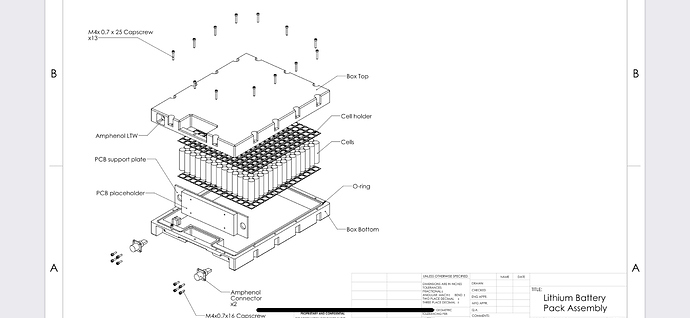
Thats true most of these boxes have 4 inches height. I am designing a performance pack with aluminum housing should receive it from cnc shop this month
Ours should be available mid March. Got delayed by corona virus
What the dimensions of your box?
16.5 x 12.67 x 3.2 inches. To host #210 18650 cells
There is some electric drawback in this design with the connectors being far from each other. Plus and Minus of a battery should be near to each other to get a low inductivity. Otherwise you need large input capacitors at the ESC where you loose some power and thereby generate unneccessary heat.
You have to have that distance somewhere when you have dozen of cells in series. Plus thats why these connectors comes with 2 awg for that current range
Thats ridiculous overdimensioned. You only need 3 kW for foiling, at 45V this makes a current of 67A. So already 8AWG is fine. Even if you have peaks of 5kW it is fine. Look at the relation of resistive losses inside the battery, the thin intercell connectors and welding spots, the ESCs resistive and switching losses and the inductivity and thereby the resistive losses inside the capacitors of the ESC and you find this design is not very balanced regarding the efforts, costs, weights and on the other side the benefits you get from dimensioning. All battery and ESC plugs are double contacts to allow the cables to be near to each other to hold the inductivity low and also to minimize EMC problems.
Beside your point about dimensions which I designed it for my board as a performance pack, none of what you said make sense unless you elaborate!
Check the lift battery dimensions as a reference:
Thin intercell connections, welding challenges capacitors internal resistance?!!, balanced?! And specially cables to be near each other…
These are just some generic challenges for any design. When you have dozen of cells in series and parallel pack -/+ going to be at the two end no matter how you arrange them! Now you can make the output connectors close To each other but at some point the pack -/+ has to travel from two end of the cells, either inside the box or outside of the box.
Plus I am packing 2.5kw which can be customized for lower energy density to reduce the size but I wanted maximum energy I can pack for my board
The distance between + and - don’t matter at all. The only thing that matters is the length of the power leads. If they are long then you need to add extra capacitors close to the ESC.
The distance between two wires determines the area they span up, so the area is the product of length and distance. The area mainly determines the inductivity linearly.
There are a lot of calculators available online, e.g. Induktivität von Leitungen as a very simple example.
And of course there are ways how to design battery packs with more or less inductancy.
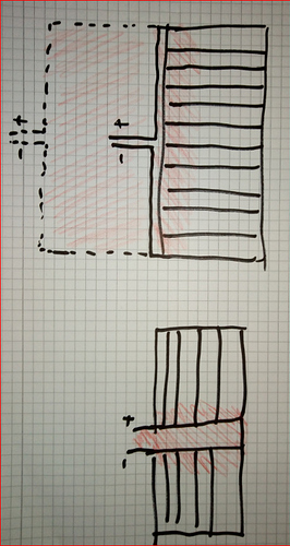
In the upper configuration you can lower the area spanned up by shorter leads which come together as near as possible, having a very low area (red colored). If you do it like the dotted lines, you get much larger area. In the lower configuration you form a U and end up with even lower area.
Inductivity of the battery and its leads in combination with switching current, like we do with our PWM ESCs leads to high voltage spikes at the ESC and its switches. This can lead to high frequency swinging and ringing, also avalanche mode is triggered by this. This needs to be prevented by capacitors, but they also have an internal ESR, which heats them up pretty nicely.
Some people even twist + and - to get ride off spikes … this has been proven
I think size and closeness are even more important than length
With a well designed ESC this becomes irrelevant. It’s already been proven that you can run 2m power leads with negligible difference on the endless sphere forum. Most guys here will be running leads shorter than 20cm so there’s no issue at all. I have run builds with and without extra caps and there was no real difference in the ripple current and voltage spikes.
Plus bms should have pre discharge control which slowly charges all capacitance and inductance in the path until it reaches the pack voltage.
Today I did a quick video of the spark free battery connection…
battery casing will soon be available.
those interested can message me.
price will be as follows:
- complete casing with the 2 amphenol connectors: 340 USD + shipping
- casing without the 2 amphenol connectors: 310 USD + shipping.
I hope to be able to ship first units around march 21st.
I am already using the first 2 sample units for myself and they work so far great.
as an extra safety I have filled the casing with epoxy. I plan also to test filling them with special 2 component silicon in order to keep so flexibility and dampen possible minor shocks.
casing can accomodate 12S14P, 13S13P, 14S12P
Maybe make a new post with basic dimensions. Then it will be easier for many to see and won’t be lost in the middle of this thread.
For those that are capable, here are some battery cases that may be able to be waterproofed easily:
https://www.aliexpress.com/item/4000402408207.html?spm=2114.12010612.8148356.19.540261daruxapn
https://www.aliexpress.com/item/32883547064.html?spm=2114.12010612.8148356.3.e0284dbcrtAWNa
https://www.aliexpress.com/item/4000401676119.html?spm=2114.12010612.8148356.9.e0284dbcrtAWNa
If they were well sealed with silicone and the surelok connectors used they might work well.
Cheap and good option for 8p configuration. NUmber of cells you can fit in is not much unless if you use tow in parallel.
hello,
I have added a section to the mantafoils site for ordering the available DIY products.
Does anyone know what connectors are used between the Lift efoil motor and the Lift ESC?

