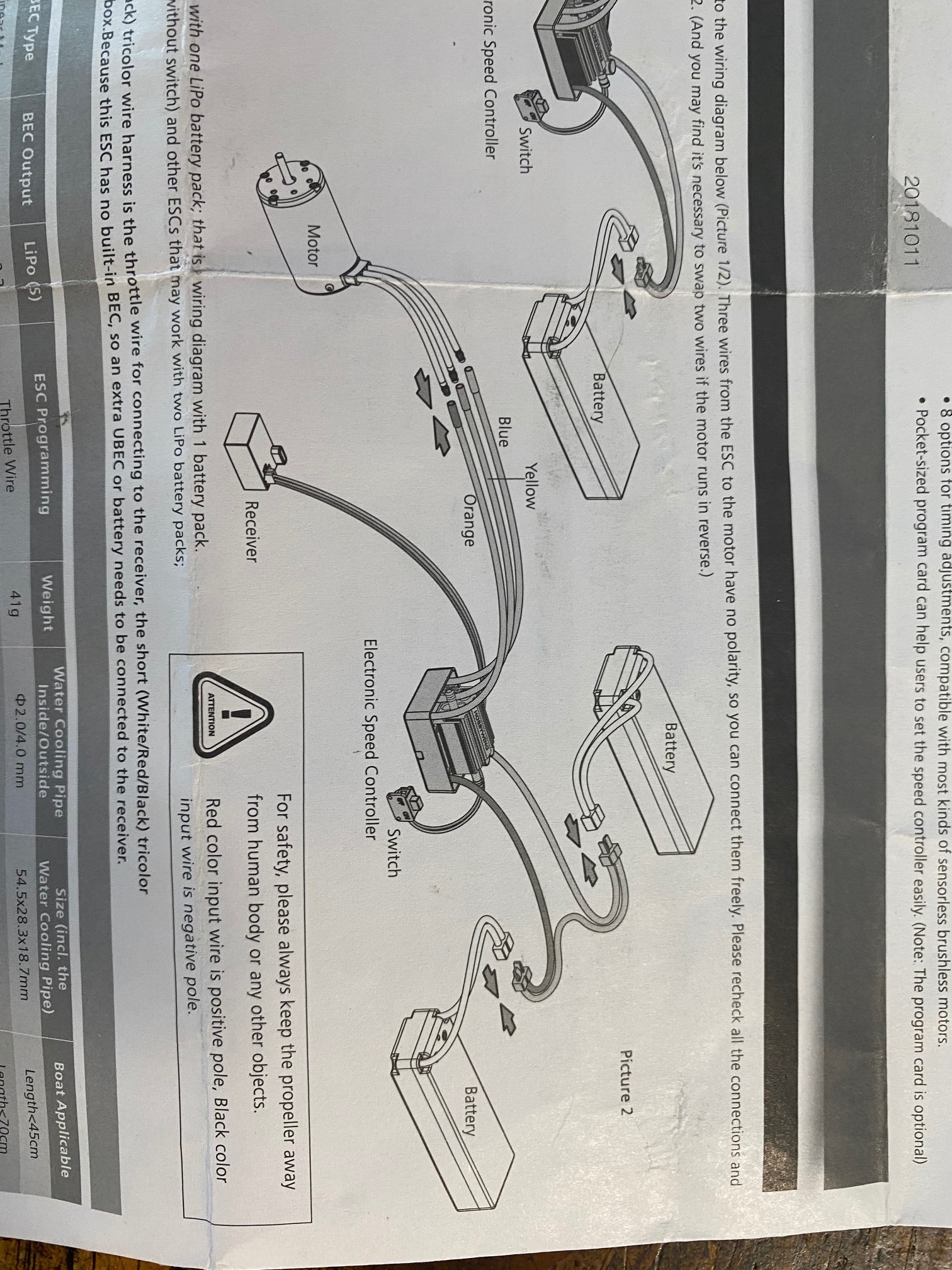
I have read the manuals, I promise, but I cannot figure out how to wire these together properly. The ESC manual in particular is lacking.
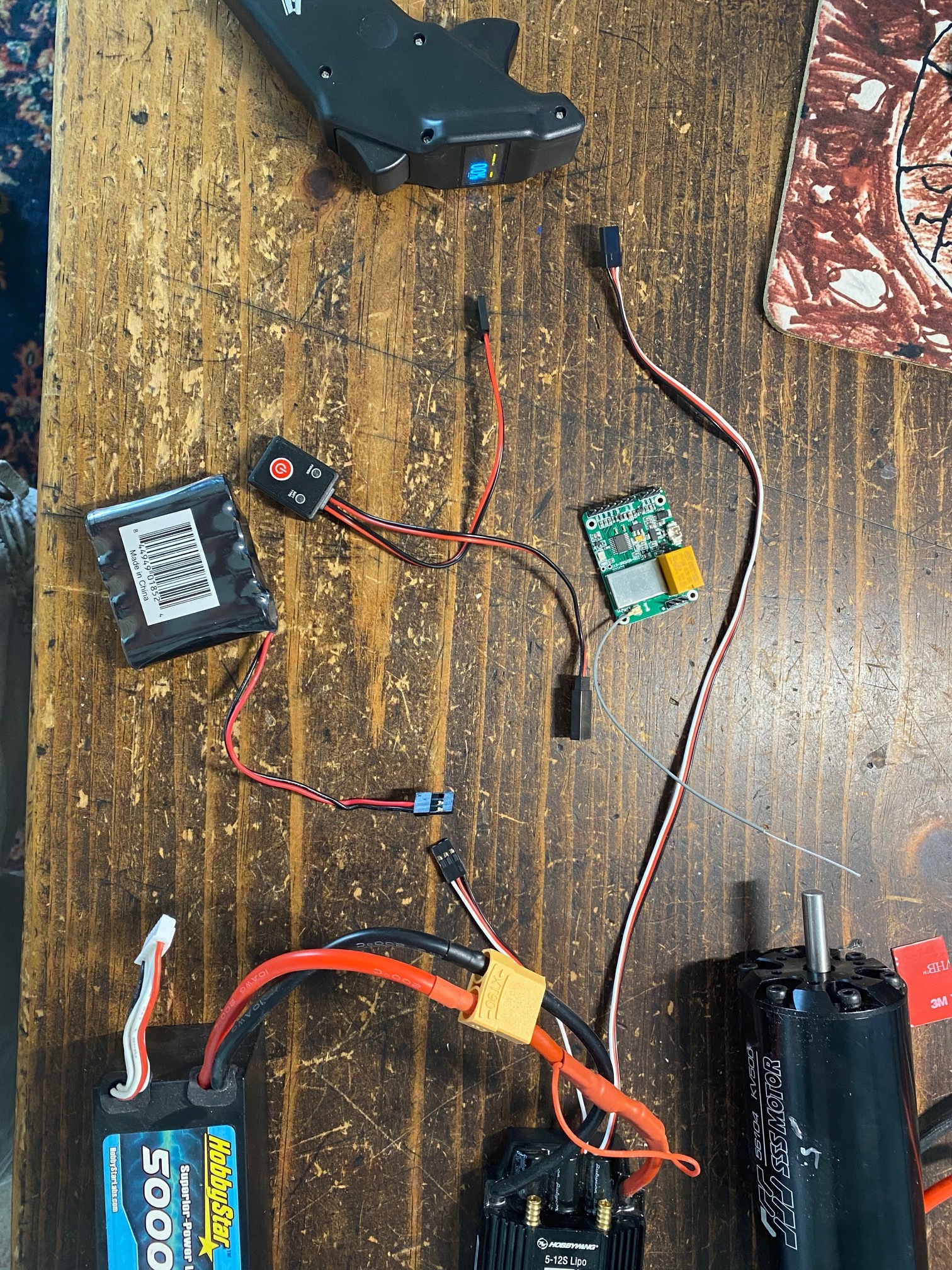
I have a Seaking 130A esc. (plus battery and motor)
I have a Maytech remote (MTSKR1905WF V2 IP67 Waterproof Remote)
I have a switch, and I have a 5v battery.
As the ESC does not have 5 volt out to power the receiver you will need to supply this to it.
That is why you have an extra 5 volt battery. The switch will need to go between the 5 volt battery and the receiver.
To power the receiver you will need to modify the 3 pin longer ESC wire.
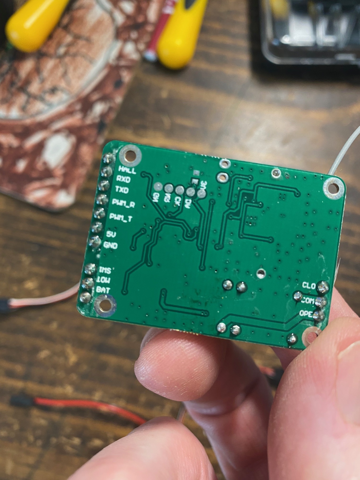
On the picture of the receiver you see GND, 5V and PWM_T.
You will need to connect the + from the 5 volt battery to the 5V from the receiver.
You will need to connect the - from the 5 volt battery to the GND from the receiver.
The ESC long wire. Connect the black wire to the GND on the receiver (the - from the battery will be here too)
Connect the red wire from the ESC to the 5V on the receiver (the + from the battery will be here too)
Connect the white wire from the ESC to the PWM_T.
The on/off switch can be connected (if needed) between the + wire from the 5 volt battery.
Maybe this will help you too.
Only pins needed are the PWM signal output.
Just add the 5 volt and ESC to it
The 5 volts out the UBEC will still need to be connected as described above.
+ (red) out UBEC to 5V on receiver
- (black) out of UBEC to GND  on receiver

RED from ESC to 5V on receiver
BLACK from ESC to GND on receiver
WHITE from ESC to PWM_T on receiver.
So. Only 3 pins used on receiver are the PWM signal output for ESCs pins (5V, GND and PWM_T)
Another question - In the default settings, the motor turns fast backwards at 0% throttle, comes to a halt at 50% throttle, and forwards at 100% throttle. Anyone know what setting this is?