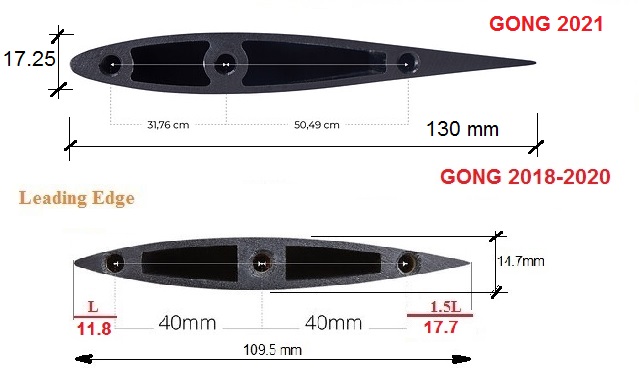
There’s been discussion on putting the ESC in a mast extension, but what about inside the mast. It looks like the Gong Alletor could possibly fit a one of the more compact VESC 6 versions, like the one from Flipsky (with heat sink and possibly also pin headers removed.
Plan would be:
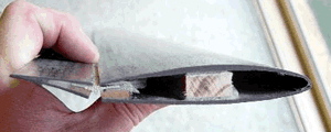
Mill/drill/cut away central solid piece of mast deep enough to fit ESC
Put ESC in place, route cables, and fill up with eposxy. Leave space below ESC to fit connectors and new central alu block to attach fuselage.
Foreseen advantages:
ESC very close to motor
Direct watercooling without any fuzz.
No need to mess around with building ESC compartment with advanced geometry.
Perhaps someone here has a to-scale drawing of the Gong Alletor mast and/or the dimensions of the Flipsky VESC 6 with heat sink removed. Or, if the Flipsky heat sink is glued in-place: hint about a VESC with similar geometry but without sink. I’ve seen pictures of ones like that with 3 caps on a separate PCB, but haven’t been able to locate the brand/retailer.
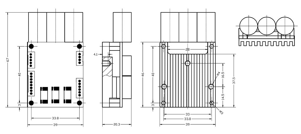
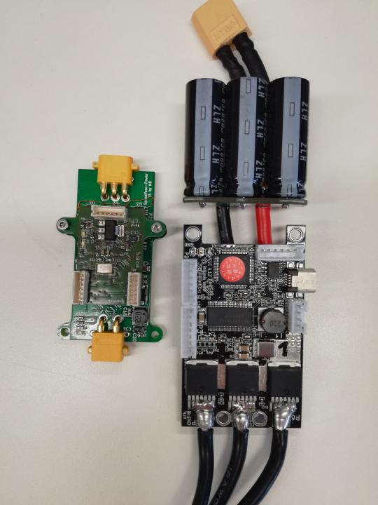
The VESC 6 with separate PCB for the caps that I was referring to is the right one in the picture below, from the VESC forum. (The left one is even smaller, but only handles 20 A and 35 V.)
It measures 18x65 mm and is very thin (especially if one unsolders the pin header). The question is if 20 A x 48 V (just below 1 kW) continuous is sufficient for efoiling (with a large wing)?
It is sufficient for flying (see @jeffM projects 18Ax 12s = 907W) but the take-off needs an extra 50% burst that is 1400W for a few seconds.
To get extra lift at slow speed and unstick from the water surface there is the flap solution used by Moth dinghies since 2000 and copied by the Taaroa iUP.
When the flap is down, you can double the lift produced by the wing without the extra current peak.
Technical solutions could be a foot-push rod with tensioned spring (or foam) actioned from the board deck or a servo motor that retracts the rod (flap deflection to zero angle) when the board takes off (unsticks from water).
ESC very close to the motor also means ESC is very far away from the battery. With a bit of reading around the VESC, you’d find out that battery/ESC distance needs to be as short as possible to prevent inductance problems that would damage the controller. The bank of capacitors that you find on the VESC based controllers is typically sized for about 10-30cm cables.
Long battery cables will also require to be super beefy once a significant length comes into play. Phase cables also suffer losses of course, but much less so than a DC feed.
So your idea of bringing the ESC closer to the motor, will make you replace 3 long 12AWG phase cables with 2 much thicker 8AWG battery cables.
The center part of the mast is also pretty critical for stiffness, and it also most likely gets involved in the fuselage/mast connection, hence why it is threaded.
Waterproofing the mast is no big deal when you only have 3 cables running through it, once you have electronics in there, it becomes super critical.
I’ll try a design with the Holybro VESC-compatible ESC, that seems to fit inside the mast without machining the center column. It’s spec-ed to 48 V, 20 A continuous and burst of 40 A. I believe with sufficient cooling this would get me foiling (just below 1 kW continuous, and a bit more to lift off the water). I’ve posted on the VESC forum asking how the 20 A (and 40 A) limit was decided. The FETS can take more, so I am suspecting that as long as junction temperature is kept reasonable through cooling, the ESC can handle larger currents. But this I am not sure of.
As for DC cable length, I think it’s easy enough to add another capacitor in parallell to compensate for the longer cables. To me the hassle of doing this seems to be worth it, with gains being more efficient cooling and easier interfacing (one less lead) between mast and board.
But I’ll definitely read up on the DC cable inductance problem, as I don’t immediately understand why the much smaller inductance of the DC cables are a problem, compared to the much larger inductance of the motor windings when it comes to switching transients. So thanks for pointing me to it!
Always good to see new aproaches but based on many vesc logs I’ve seen (including mine), I doubt that you will get enough power to launch. With a big 1600cm2 wing I need at least 60A@12S for takeoff. That’s in calm water.
Yes, it’s on the edge. I’m very curious as of what dictates the 40 A (burst) limit of the Holybro VESC. If only temp, I am quite sure it will be quite fine to run higher current for lauunch…
also, how are you going to configure and tweak your ESC? USB cable/ Bluetooth chip also inside the mast? How about your RF receiver? Will that work from down there?
I was thinking to route a cable with waterproof connector down toward fuselage end for USB communication with ESC (with fuselage removed) and another cable up for remote radio PCB. Yet to see if it’s possible to have almost 1 m cable to radio PCB. Hopefully I can lead the coax up the same mast duct as battery DC without suffering from signal disturbances, otherwise I’ll bridge to the other mast duct inside the motor mast clamp.
Whether there will be sufficient signal with the radio PCB just at the mast mount, or there is a need of an antenna that sticks up from mast inside board remains to be seen. (Of course hoping I can get away without the extra antenna, but might not be possible.) Perhaps especially not if I end up covering the board core with carbon instead of glass.
If anyone has advice on thermal potting to use, I’m happy to hear. Particularly if there’s one that doesn’t cure as hard as epoxy, so it’s possible to scrape out from inside the mast, should I at some point kill the ESC.
I’m thinking of ordering a Flipsky VX3 remote and Flipsky radio PCB tomorrow, but am open to options if people here have suggestions.
The ESC (spare cables and connectors) and mast was ordered yesterday. Seem to be some lead/shipment time, but looking forward to get hold of the components to do some dry testing.
Thanks. There’s also several testimonies suggesting that I’d need somewhere in the 1.5-3 kW range to lift. So the make or break point of the design as far as I’m concerned is how long the Holybro VESC can run at 40 A, or possibly above. Will have to read up on whether this is limited by thermal aspects only and if there is (at least on-board hardware support for) thermal safety slow-down or shut off. Overview manual suggests there is, at least on the official hardware version.
…if signal quality with radio PCB in top of mast turns out an issue, I want to look into using an IR transceiver for the UART, where one end is potted in (IR) transparent compound at the mast top, and the other under the board. Seems from quick search that they draw about 50 mA, which I hope the ESC communication port 5V can source.
Rated continious , max and burst ( as it goes a part in fire )
You need some speed ( rpm) and some thrust (torque) : propeller design will play a lot
My guess : with the amp burst for a start , this vesc will go apart in 10meter or if the safety kicks in ,the propeller rpm will stop to soon to give you enough speed
OK, I feel like playing devil’s advocate here, but you thought having 3 phase wires running inside the mast was too complicated, and now, you’ll replace that with two bigger battery cables, some extra capacitors, a USB cable, and an antenna, and a lot of waterproofing material to keep all of that well protected.
And the cost of that concept is to force you to use a tiny VESC and pushing it to its limits, while not even sure if it will perform well enough to achieve liftoff before self-destruction.
Don’t get me wrong, it’s cool to see people explore some new avenues, it’s not my money nor my time that’s at stake, but I’m not convinced of the benefits here, compared to using a properly sized ESC that will deliver the required power, and that will not run as hot, if spec’d generously with some headroom and decent heatsinks.
Definitely legit view in my opinion! And actually, we plan to run an efoil building project as student project in the fall. They’ll just a conventional design, so I was thinking of doing something different during summer (or whenever supplies show up) to try if it works out.