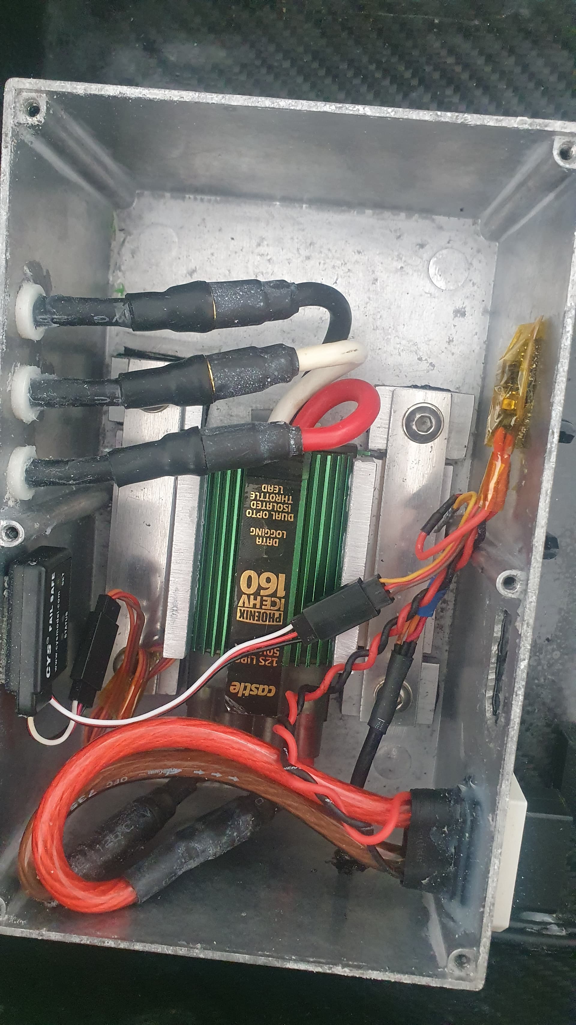
Currently I use a castle creations HV160 ESC which is rated at 160amp max continuous, I actually never get near this number when efoiling using 60amps to start and between 20 and 30 amps when up on Foil.
I’ve heard that when an ESC is used on the lower end of its abilities it works harder switching and therefore less efficient.
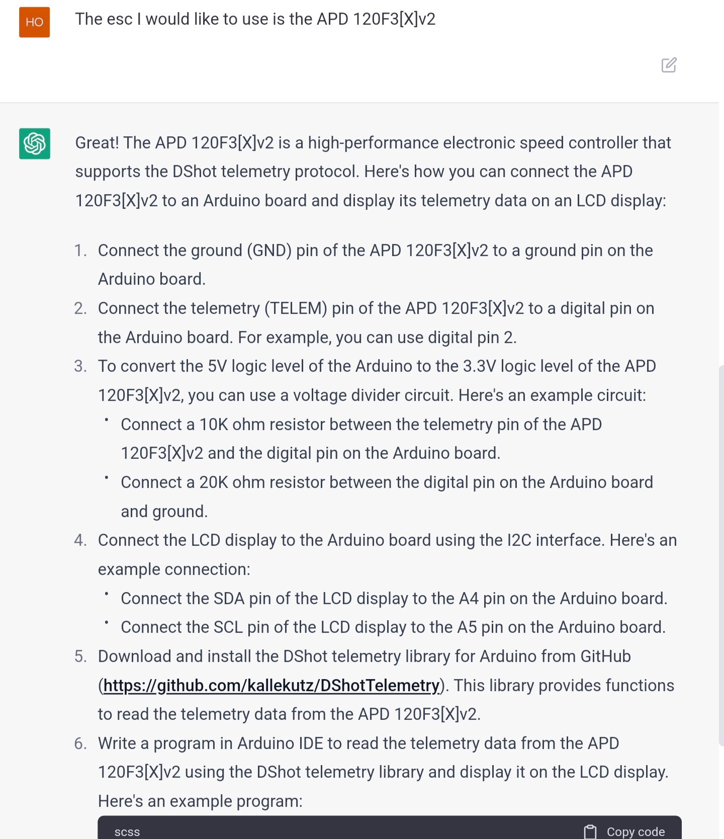
What I’m getting at really is choosing another ESC to test which is rated lower, I’m thinking of trying out the
APD 120F3v2
Any thoughts on this choice considering the low power I’m currently using?
I’ve got the APD 200F3[X] but haven’t got it in the water yet. You will need to add a heatsink and possibly a cap bank to the 120A though. Back in the day I used a Yep 120A watercooled and it ran fine…
Yes, it will be clamped inside an aluminium box and the box protruding or flush with the bottom of the board like my current setup uses. Works great, temp never gets above 35c
Eventually if the APD 120 works OK then I’ll make a aluminium adaptor plate where the mast clamps on, the APD is so small + caps it won’t add much thickness.
Similar to how JeffM cast an adaptor.
A clarification on this:
An esc with higher current capability normally has lower resistance mosfets or more mosfets in parallel and that equals a lower total resistance - in this regard the losses in the esc are actually lower with a higher current esc.
Regarding the switching losses, this is caused in the regulation of the voltage by PWM and switching mosfets. In theory the most efficient is to have no switching losses, (mosfets are run in ON mode all the time) but this (almost) never happens as motors aren’t run in full throttle and full speed for any longer amount of time.
In reality the switching losses aren’t large even if you compare two different drive voltages.
You’ll find better possibilities to get higher efficiency with 1) having a motor and propeller that is running in their optimal efficiency range and 2) having enough battery to decrease resistance losses in the battery.
An exemple:
A 21ah pack of 14s7p 30q cells, internal resistance is 14x30/7 so 60mohm
65161 motor has somewhere around 30-50mohm internal phase resistance depending on kV - so losses are higher in battery than in the motor in the example.
An esc with good mosfets in comparison can have a fraction of the above. The apd200f3x states 0.55mohm resistance, that’s more than 100 times lower than the battery losses. At switching the esc losses are a tiny bit higher - but still small in comparison.
Note that the switching losses are frequency related and that the diagram starts at 100kHz whereas a normal ESC switching is 16-20kHz.
Way back i had an excel sheet from either rcgroups or endless sphere that calculated total losses at different duty cycles. Can’t seem to find it now unfortunately.
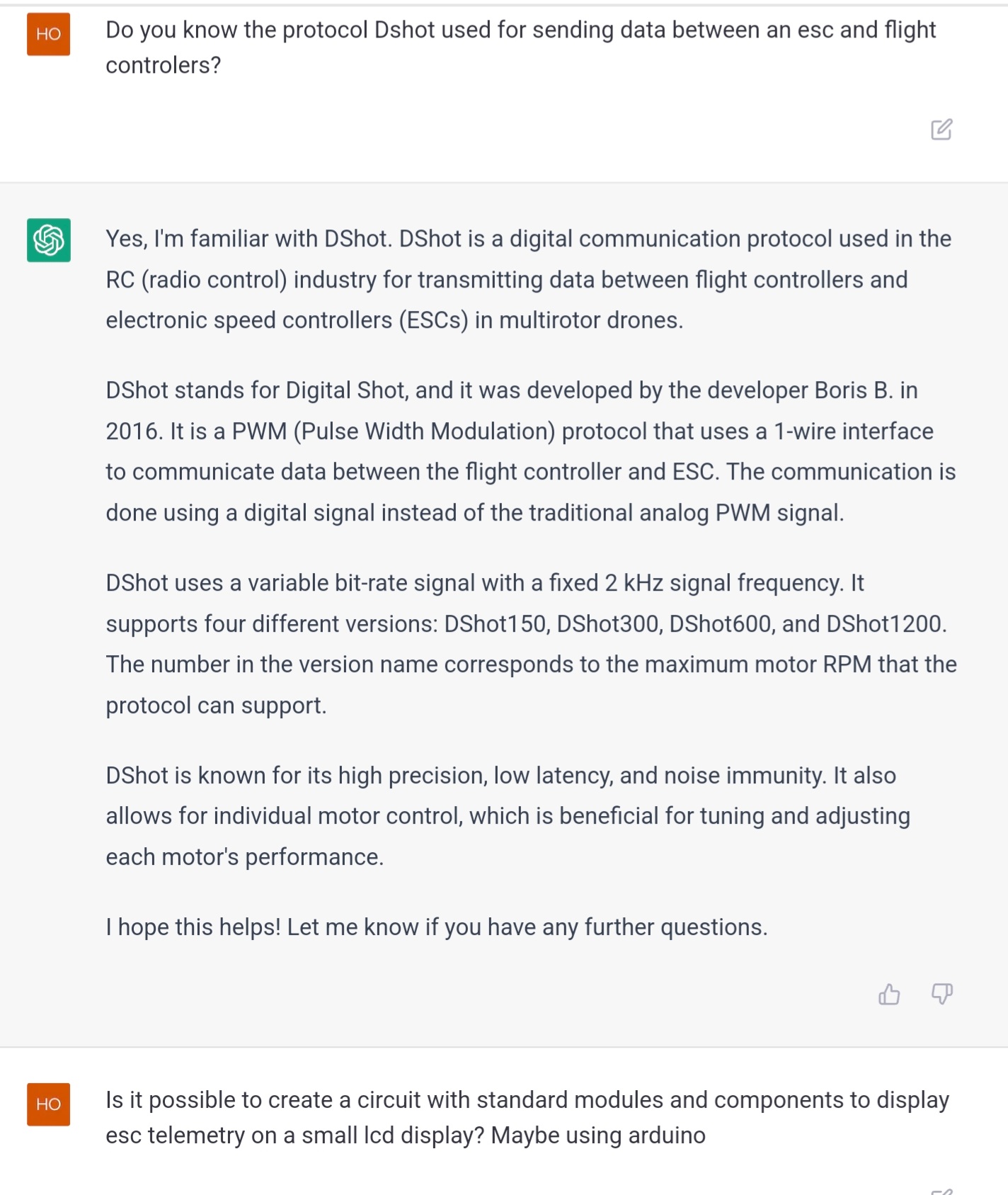
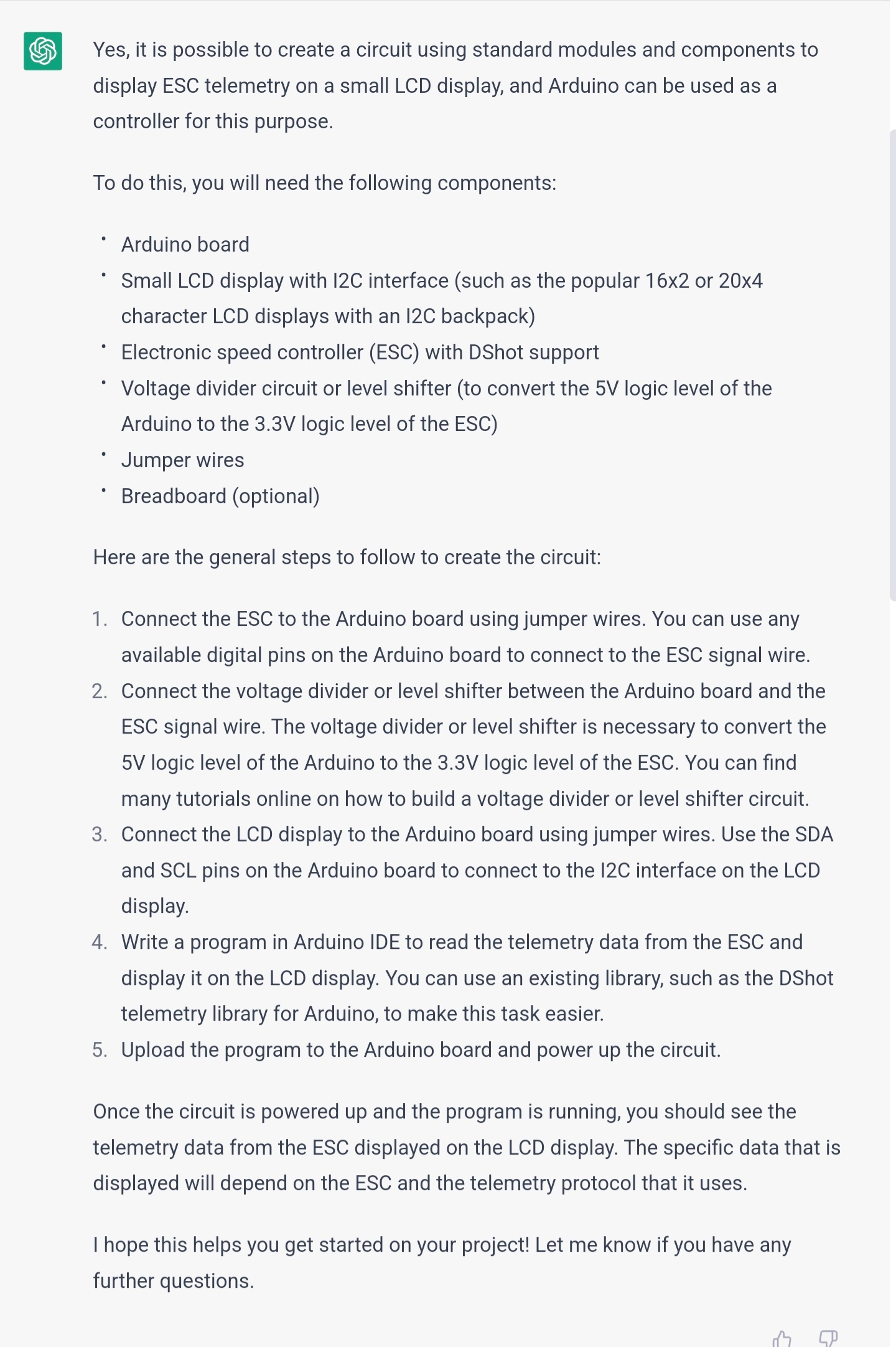
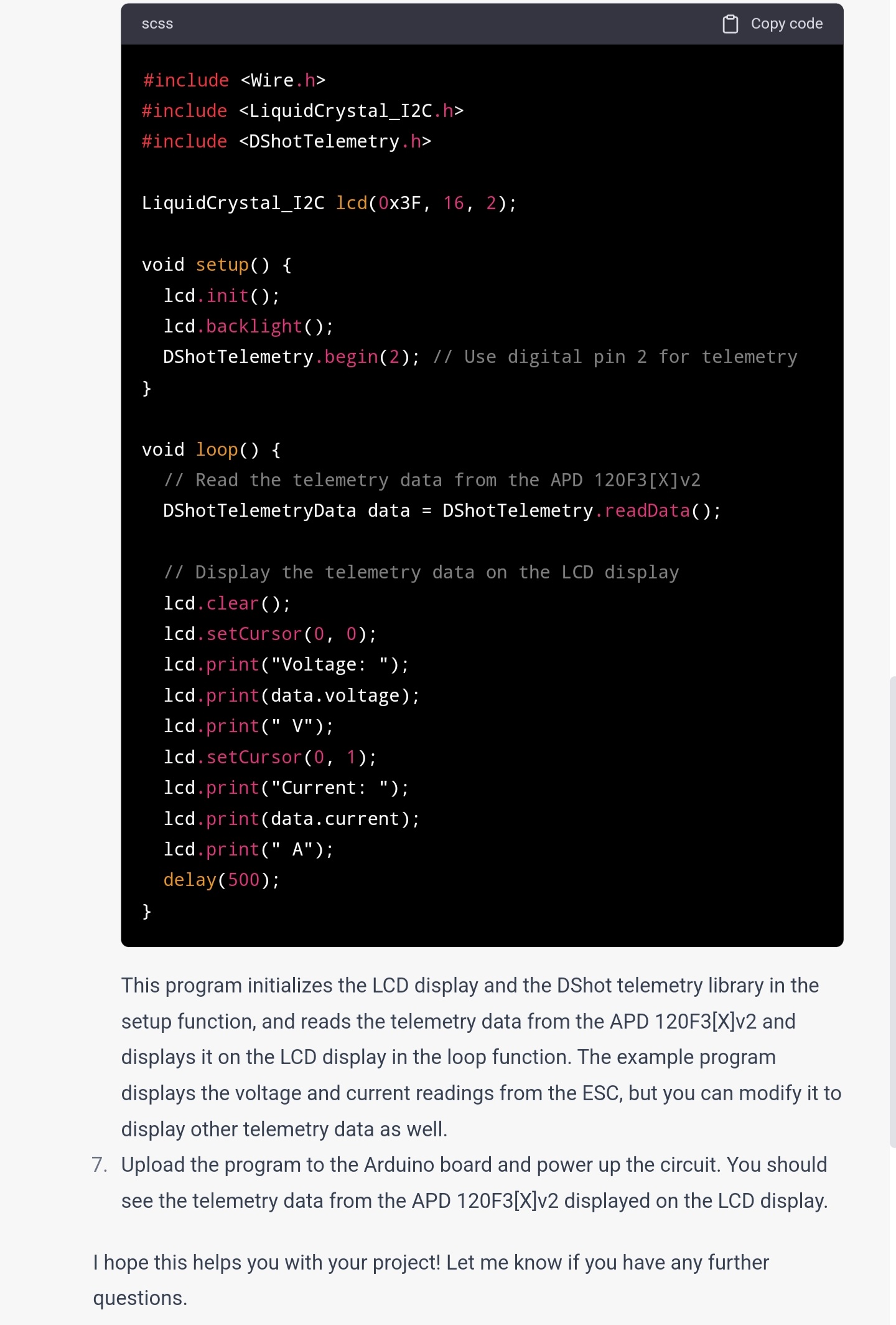
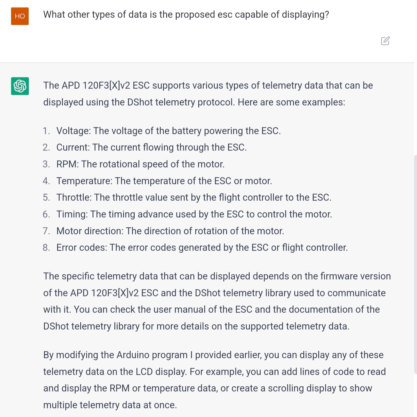
I was looking through the documents for the APD ESC’s and they use a communication protocol called Dshot, this can output telemetry from the ESC but there isn’t anything avaible to simply output this data to, so, I asked openai’s chatGPT for assistance, I don’t have the knowledge to program arduino but I can upload sketches and build simple circuits.