Hi folks,
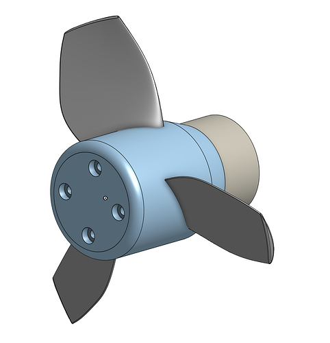
I’ve started to dig into propeller design, since my outrunner has these four mounting holes. Initially I designed an adapter for a 2.5HP propeller, but the propeller I bought turned out to be quite heavy (about 400g) and made of aluminium. I don’t think the 3D printed adapter would fare well with such heft, and suspect the printed shaft to shear pretty quickly.
My solution is to try to make a propeller that “wraps” around the outrunner. The only prop I’ve seen on this forum that does this is this one from FR.
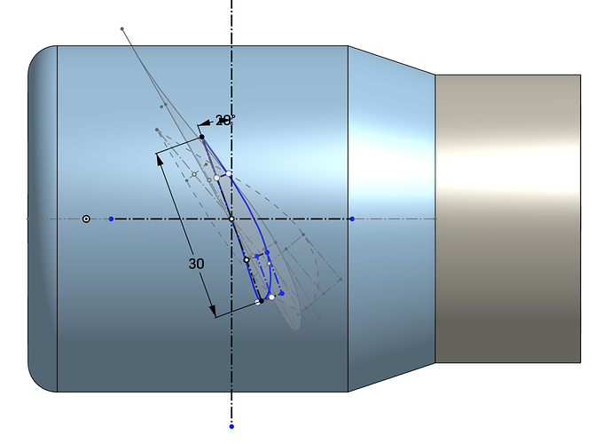
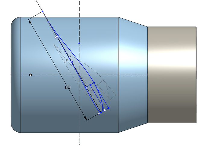
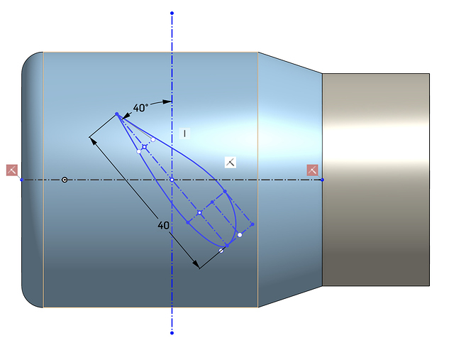
Down the line I’ll design a duct, but first want to get the geometry of the propeller right. My approach is to specify three cross-sections of one propeller blade, and then loft around them. The MIT prop pdf I’m using illustrates these as circular cross-sections, but I figure my approach should be close enough?
Here are some calculations:
6S = 22.2 V
Power = V * I = 22.2 * 30 = 660W
RPM = V * Kv = 22.2 * 140 = 3100 RPM
Say I want to go 10 mph (goal is to plane, not foil),
pitch = speed / (rph * (1-slip))
pitch (in) = 10 mph / ((3100 * 60) * (1-0.5)) * 63360 (in/mi) = 6.8"
My prop ended up with a smaller pitch at 4", and diameter is 6.6".
Here are some cross sections, not sure how else to talk about this…
I have no idea how to estimate slip, and have no idea how to know how fast the prop will actually spin in the water, or how to incorporate the total weight of the boat and rider (~100kg).
Any feedback on the profile of this prop?
Thanks,
-b


