Flipsky FSESC75200 quick teardown

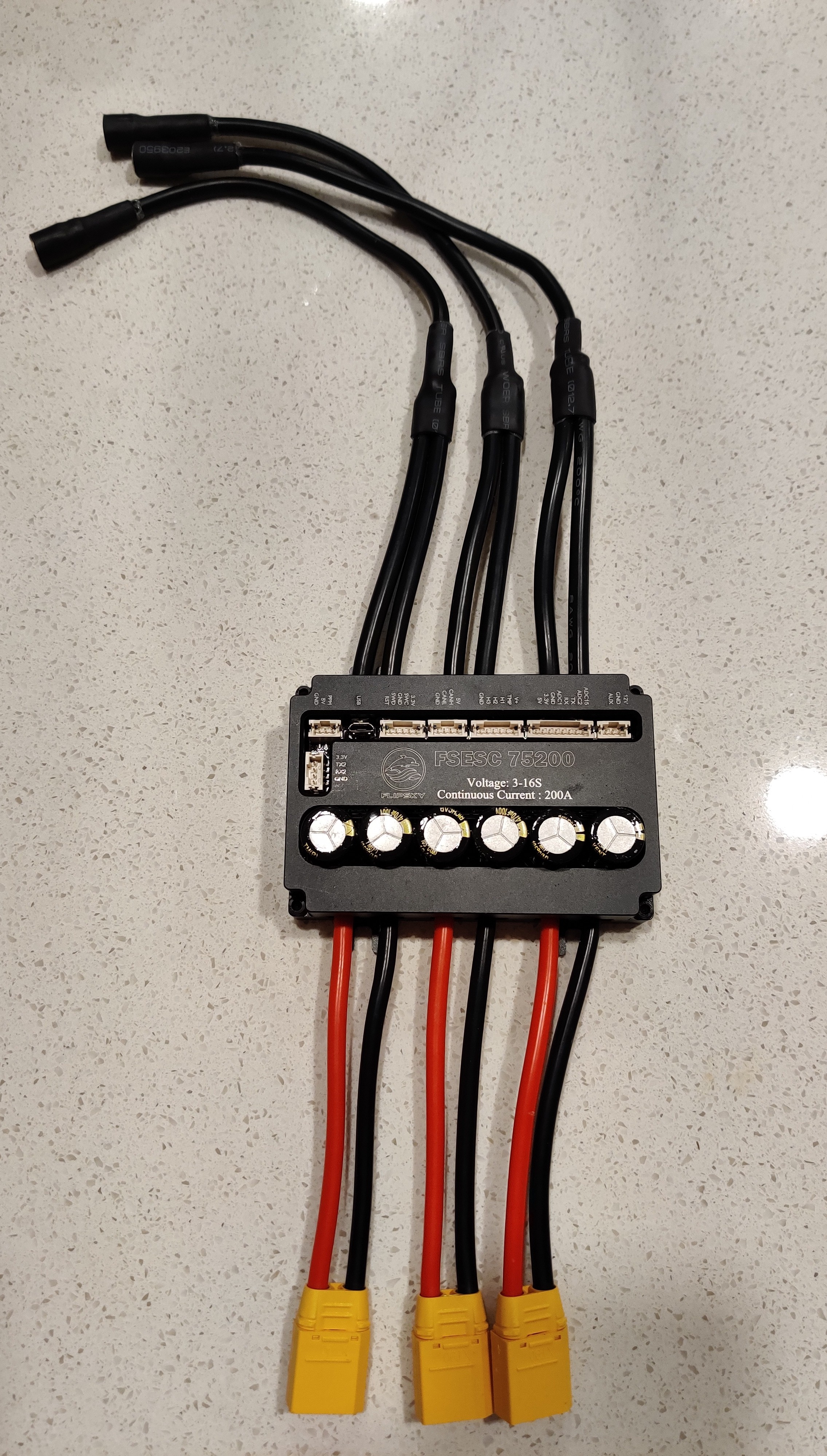
Hi! While waiting for my board and summer, I decided to conformal coat and inspect my FSESC75200. It will be going into an aluminium box, and it will be submerged in mineral oil. I’ll probably use thermally conductive epoxy to mount it, and then epoxy some thin copper tubing on the outside of the box to cool it.


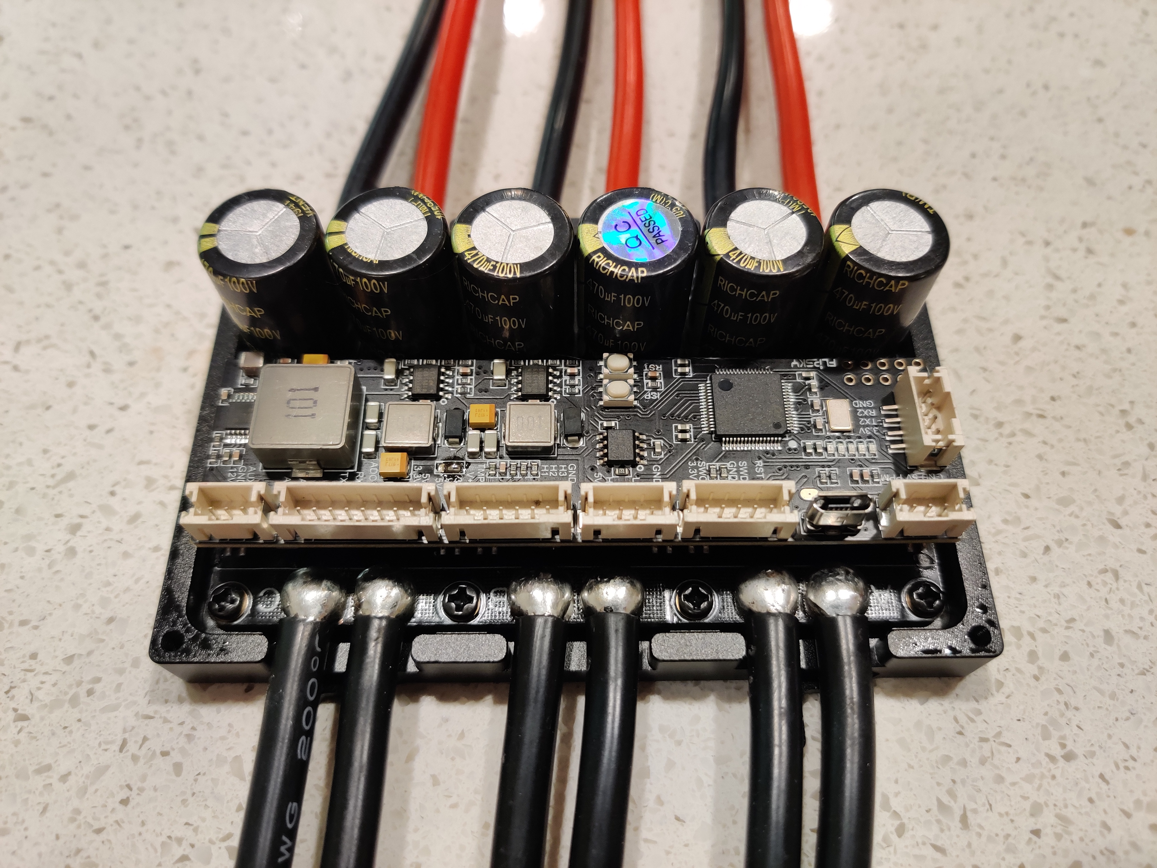
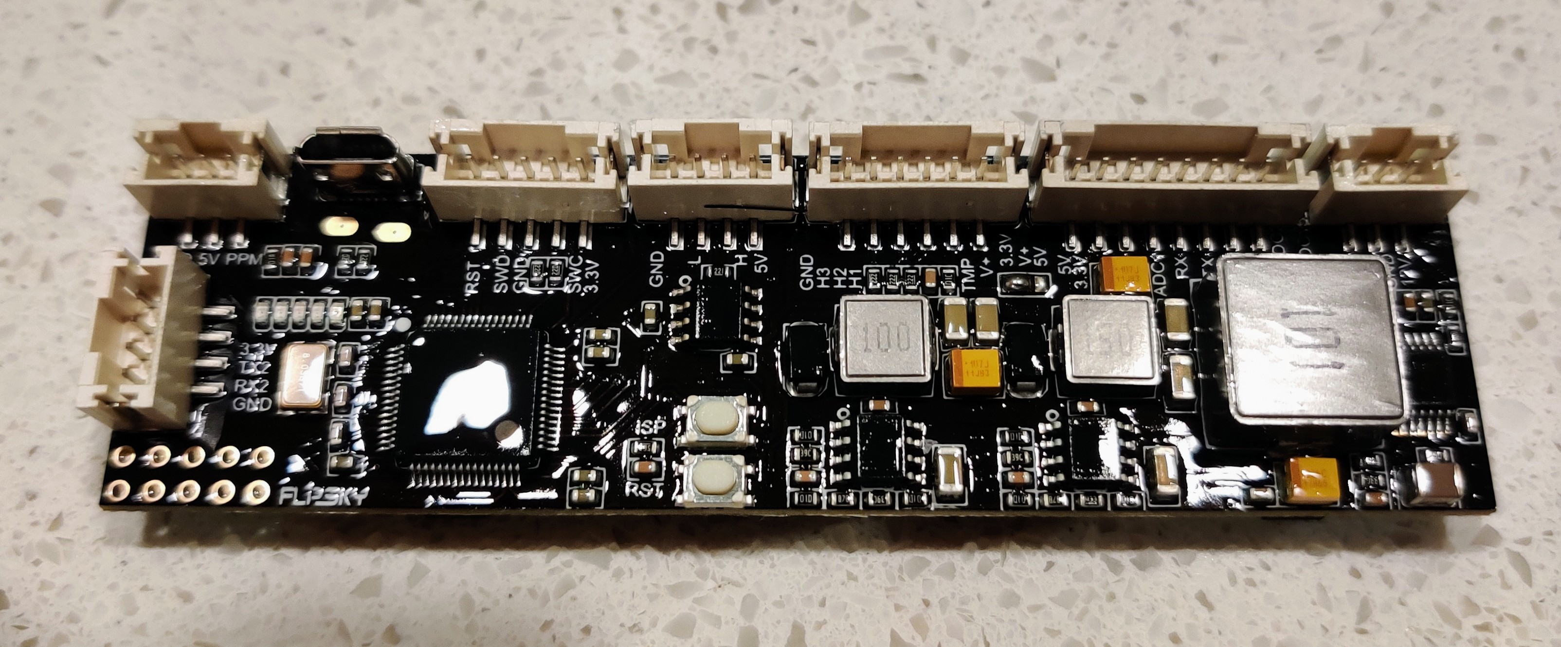
Upon first glance, without the top cover, it looks nice and clean. Minimal residue on the PCB. Solder joints look good enough, but maybe a bit on the dry side on the data connectors.


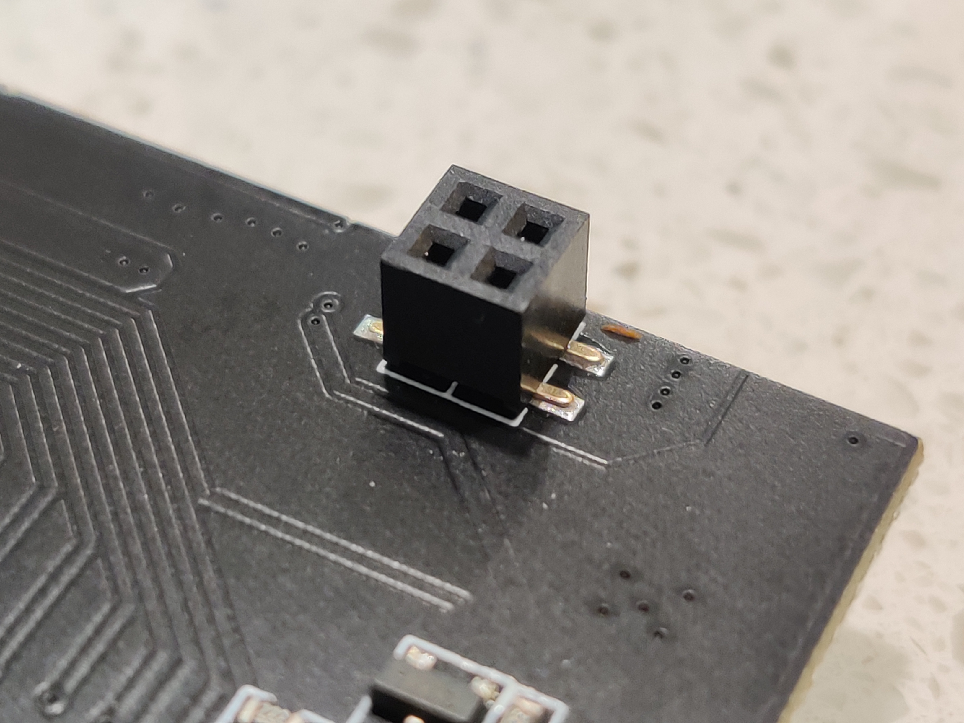
While taking off the top PCB, I noticed that one of the interconnects on the top PCB was starting to fail and come off. Luckily it did not rip the pad off, and it was actually a solder joint that failed. I think Flipsky engineers wanted to avoid melting the interconnects, but while doing that, they ended up with very weak solder joints. All the interconnects are like this. I would recommend to check yours.


Added some flux and solder to all of them. There is quite a significant ground plane on the PCB. Pre-heating the PCB with a hot air station made the soldering much easier.


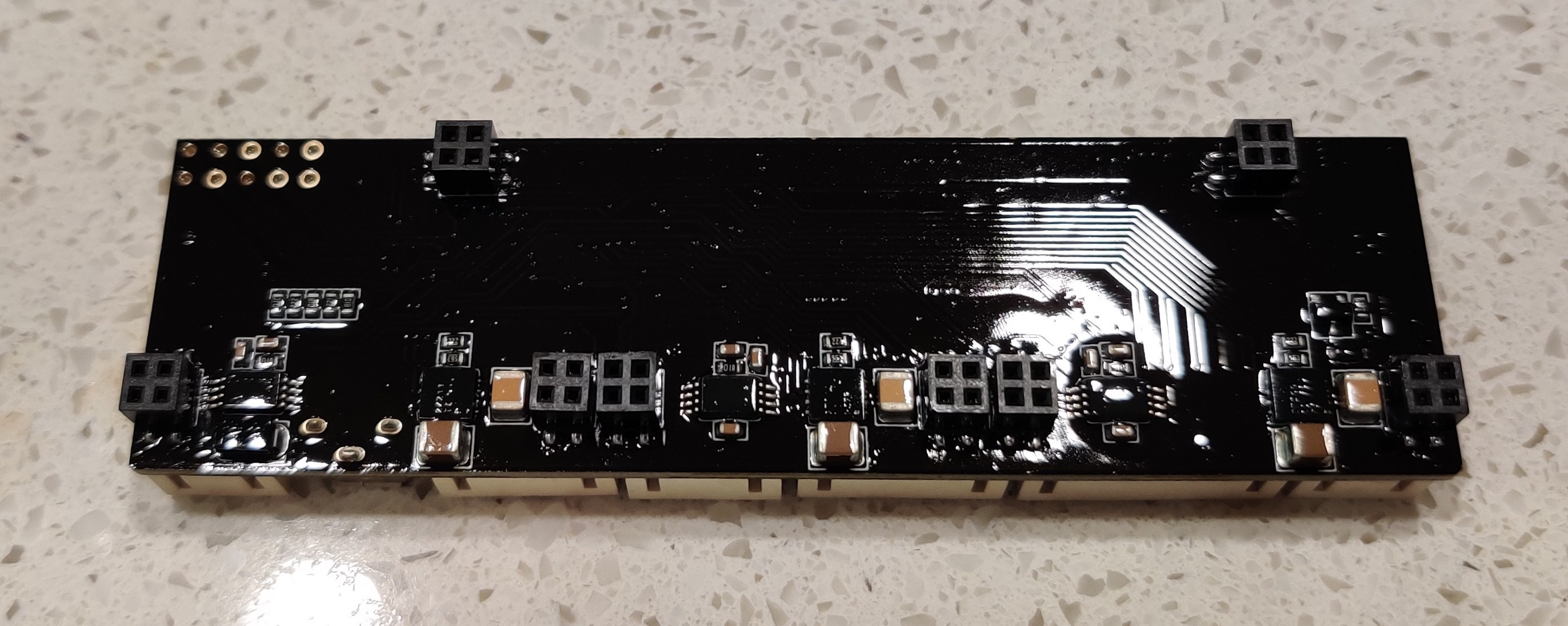
The bottom PCB looks nice as well. A bit more dirty than the top PCB, but very much ok.


The PCB took some effort to detach, due to the semi sticky thermal pad. The pad is pretty thick. It came off without breaking, but I had to be quite careful.


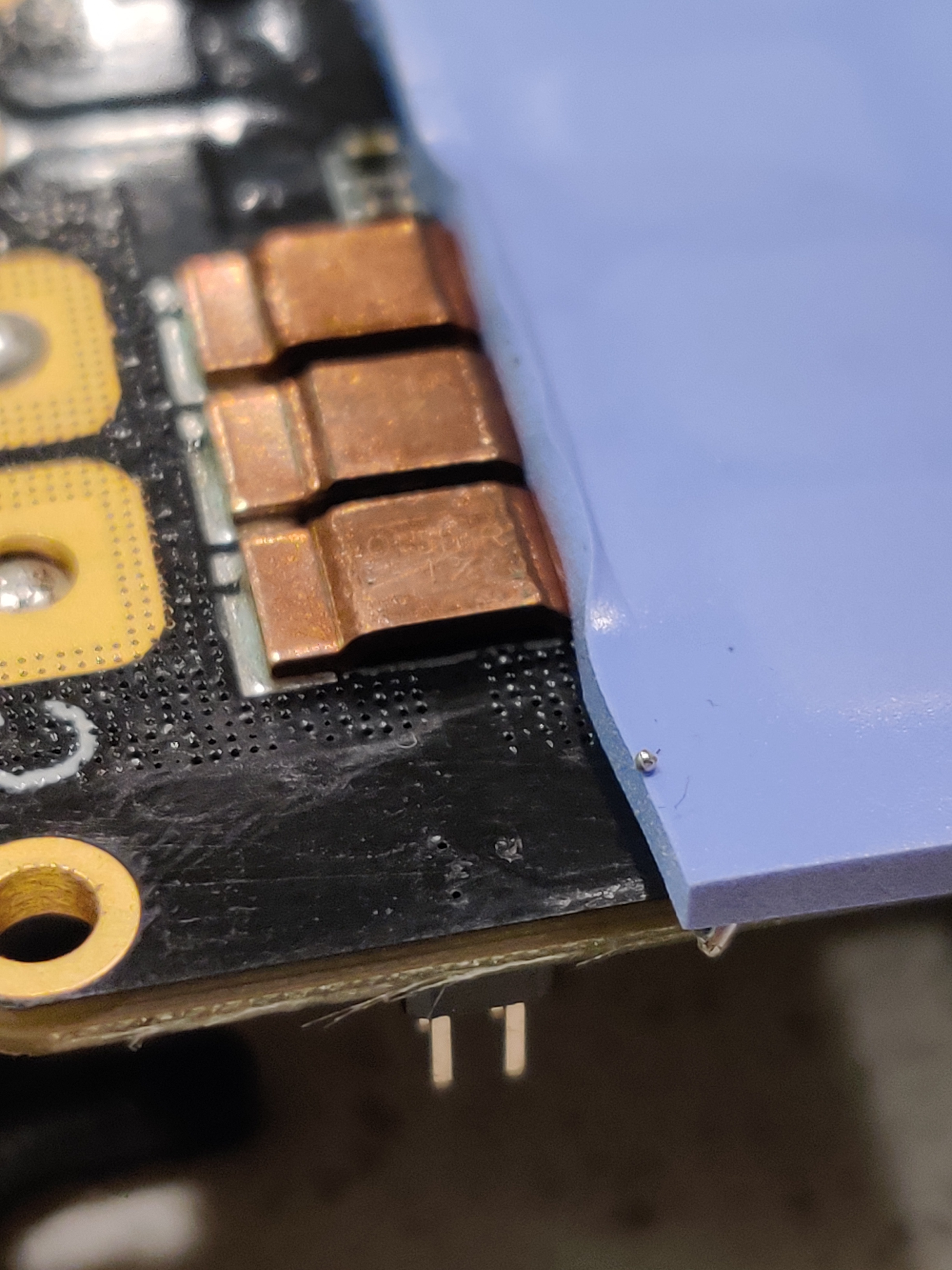
I found a piece of solder that was stuck to the thermal pad. It came off easily. It used to be pressed against the heatsink and thermal pad, so it probably would not have caused trouble in the future. Inspect yours.


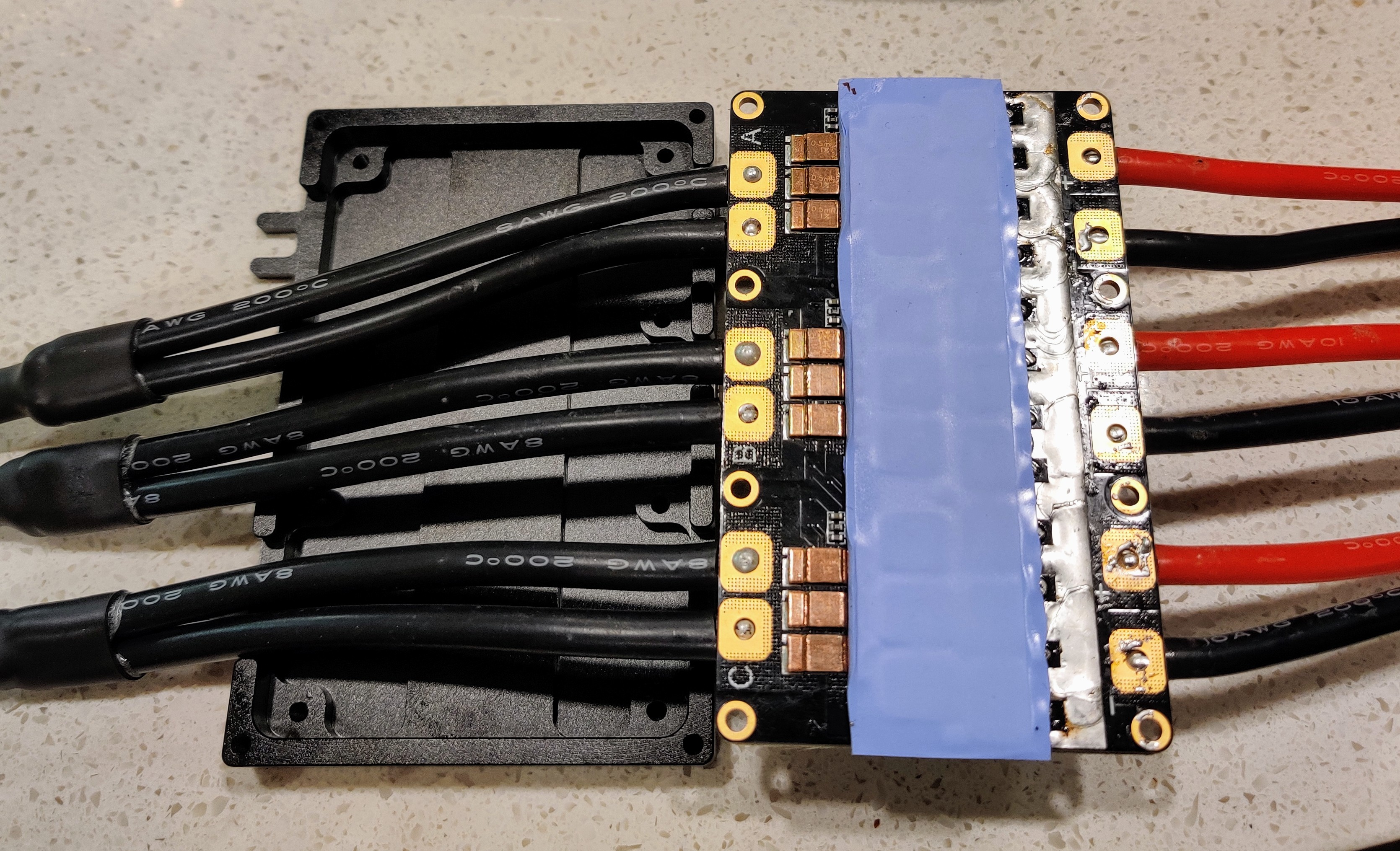
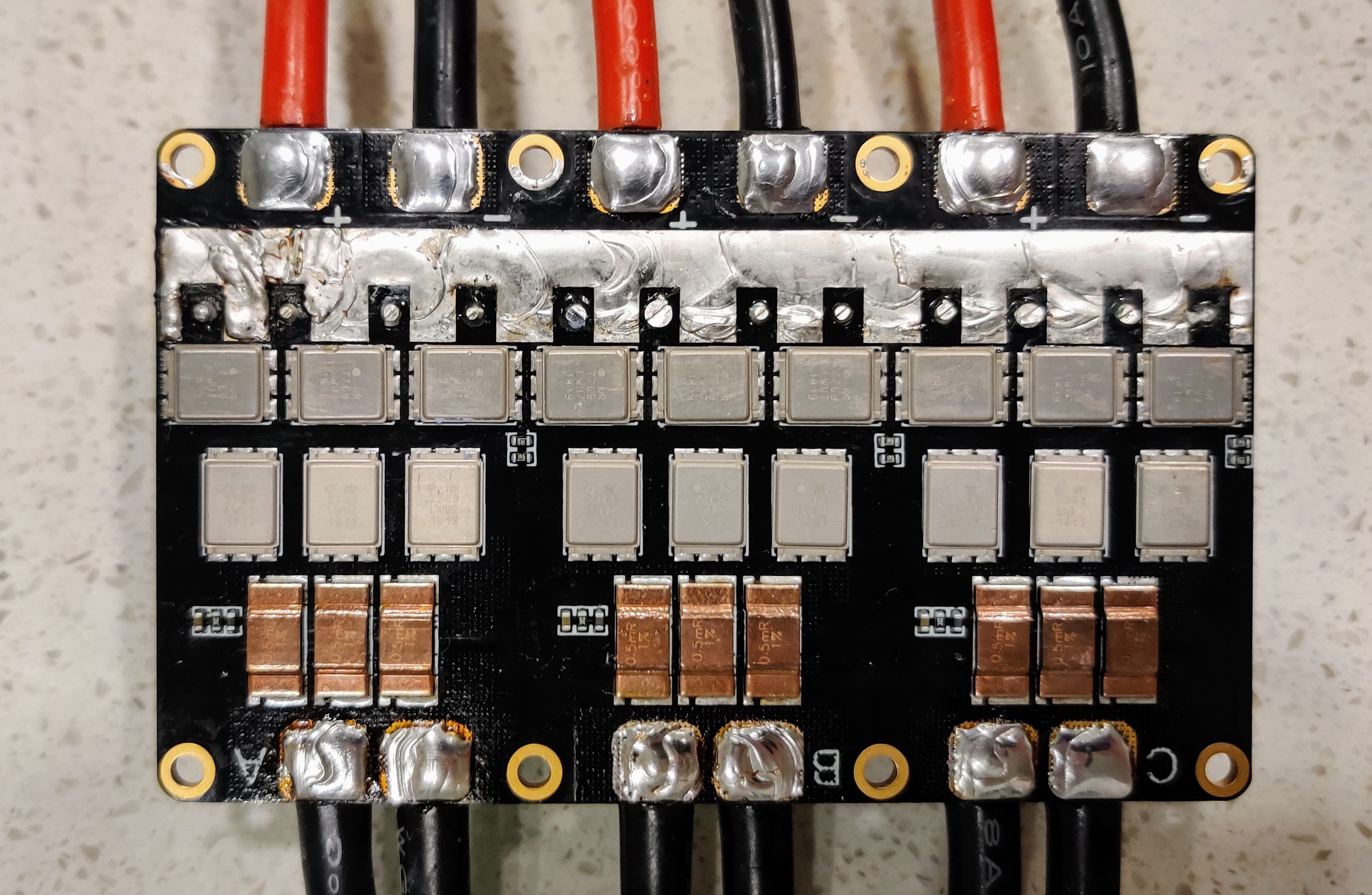
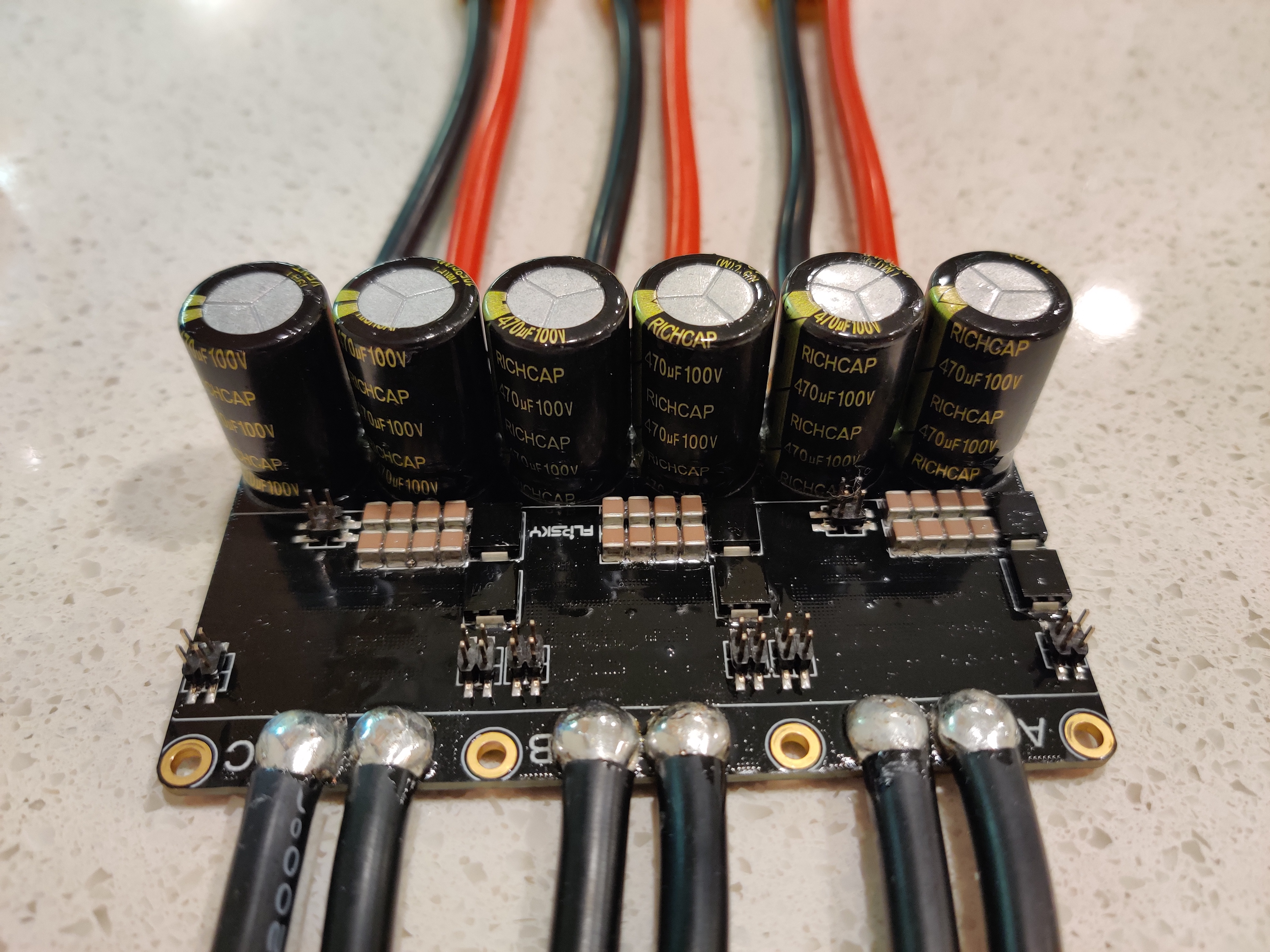
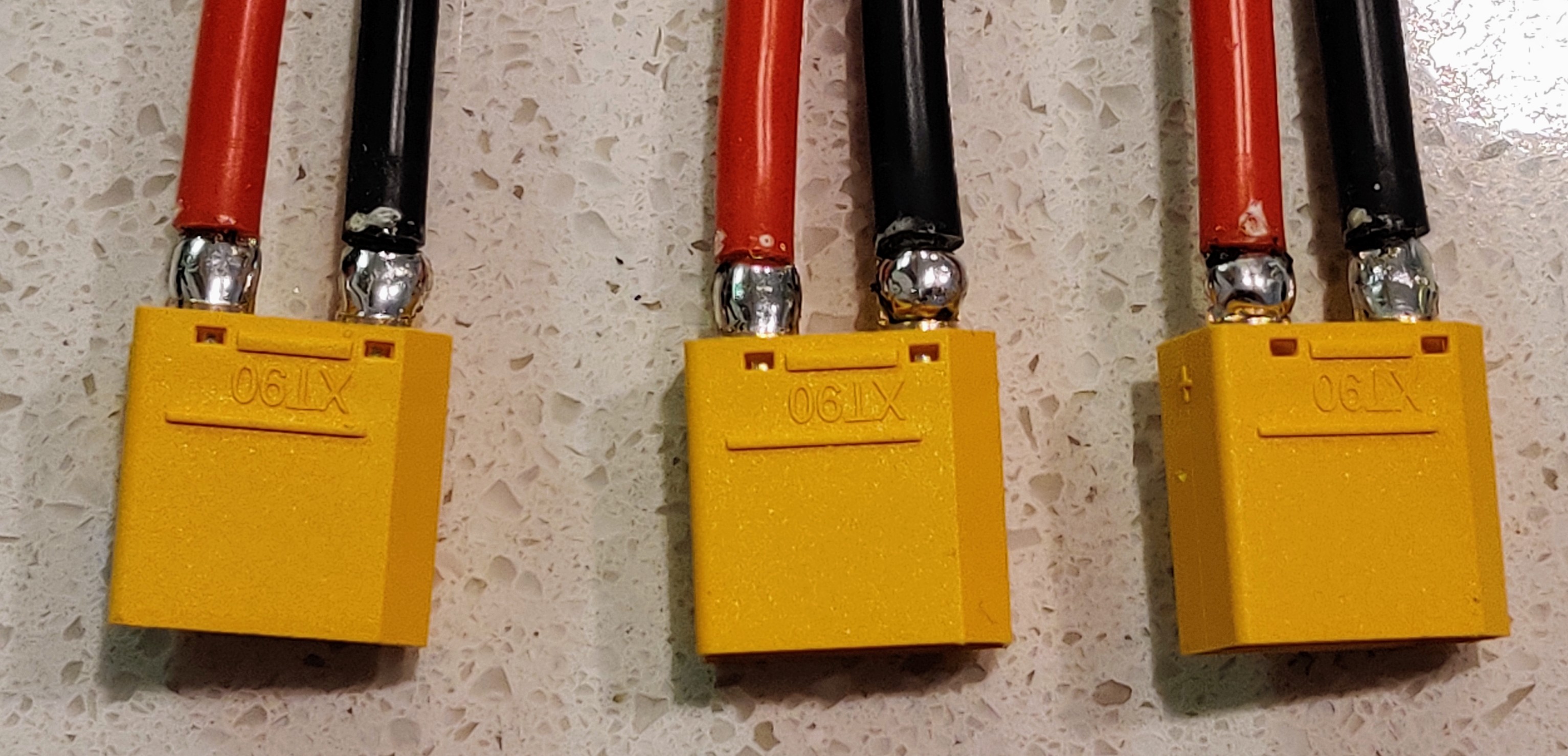
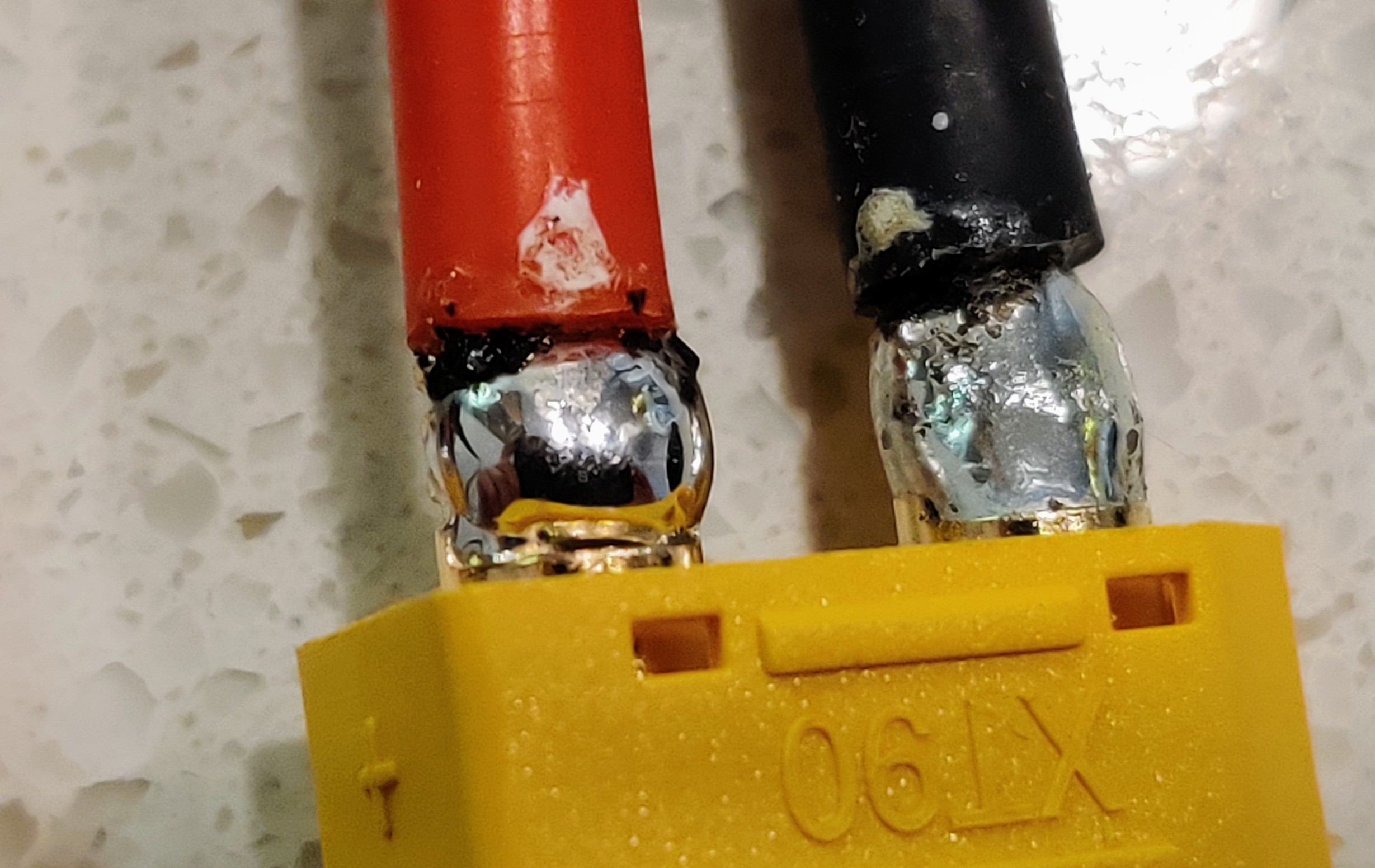
Nice directFETs. Massive ground plane as well. The solder joints on the output wires weren’t too good on the bottom side, and there was some solder that wasn’t really well connected on the golden pads.


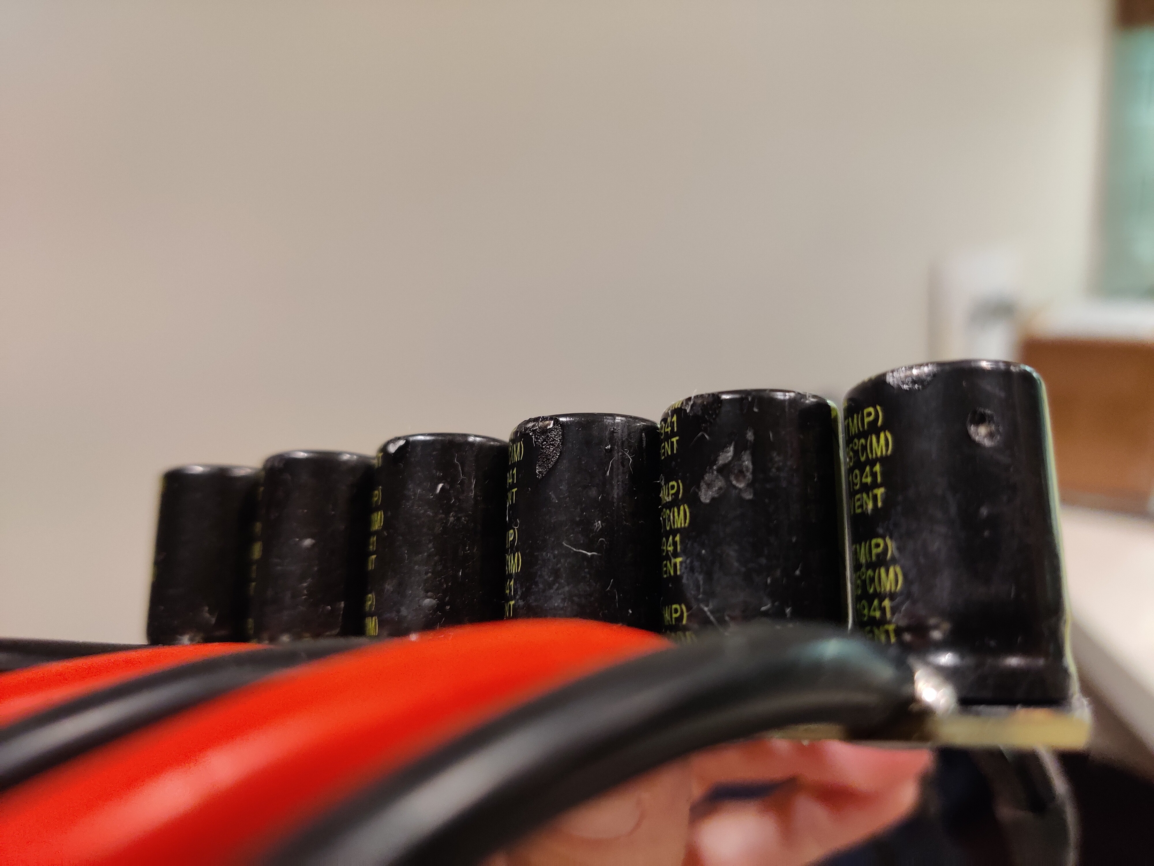
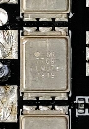
The sleeve on quite a few of the input capacitors was damaged. It looks like damage from a soldering iron. The metal can seems to be ok, so conformal coating will fix this.


Input and output connections cleaned up. This took a while, since the ground plane is massive and sinks a lot of heat. I managed to do it with an 80 watt iron, after preheating the board with the hot air station.


I started the conformal coating process. All boards and sides were coated. I avoided coating the top of the directFETs.


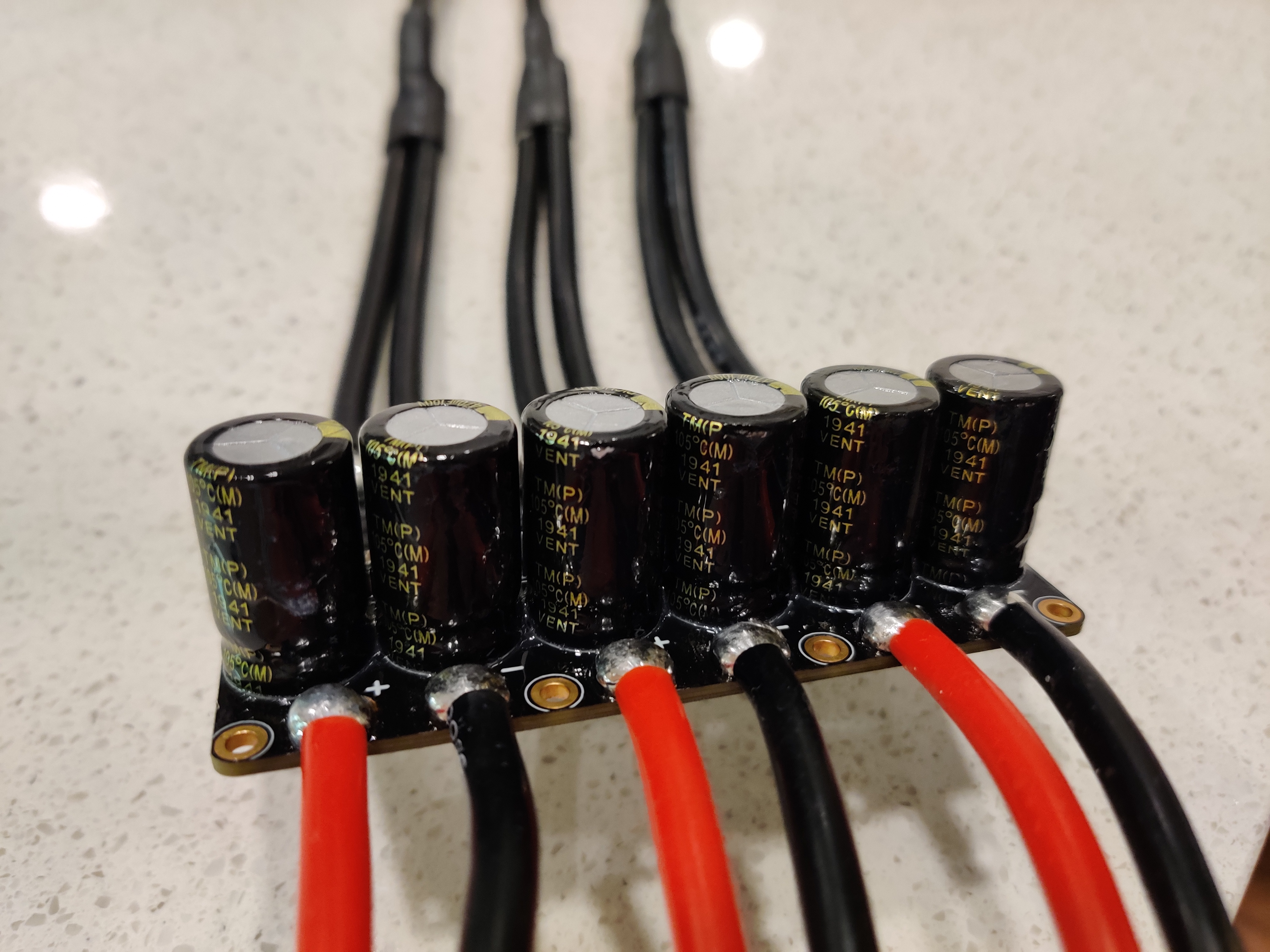
The caps look pretty good after coating them. I also removed the FS QC sticker and coated the top side of the caps. I applied quite a lot of conformal coating to the root of the caps, since it nicely wicked under them. An added benefit is that it will hold the caps in place (good against vibration). Unfortunately there is nothing holding them by default.


Topside of bottom PCB coated.


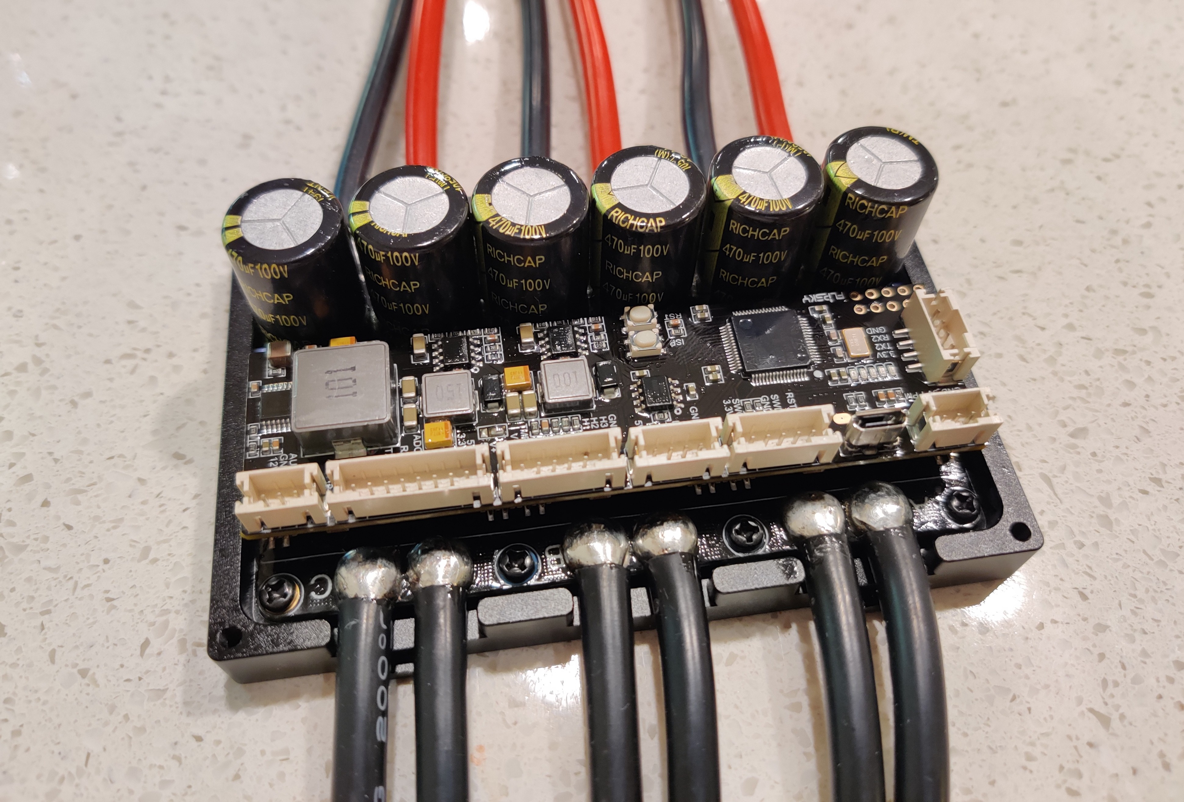
FSESC75200 almost fully reassembled. I used locktite in the screws that hold the bottom PCB and top cover. Reassembly went without issues.
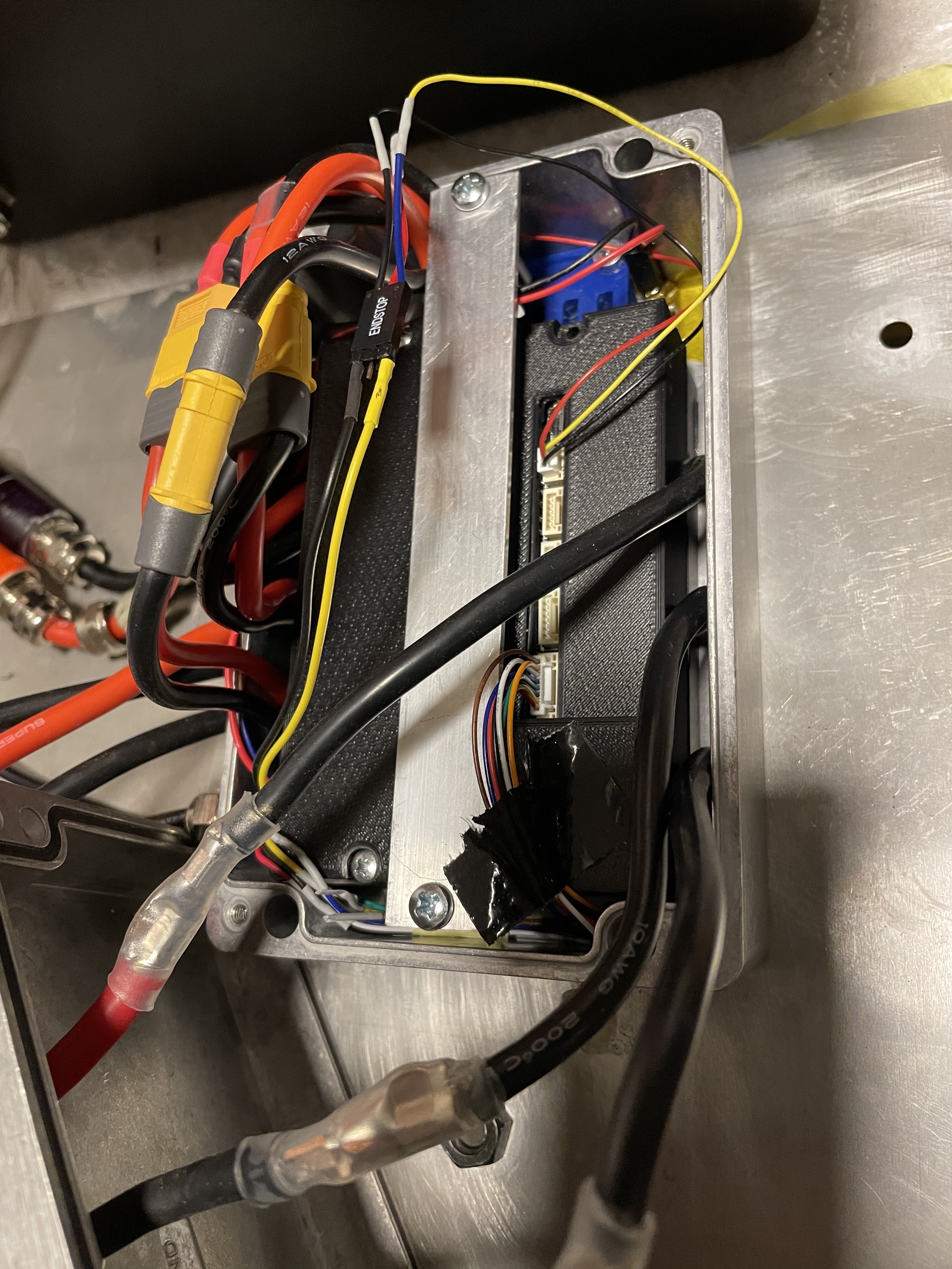
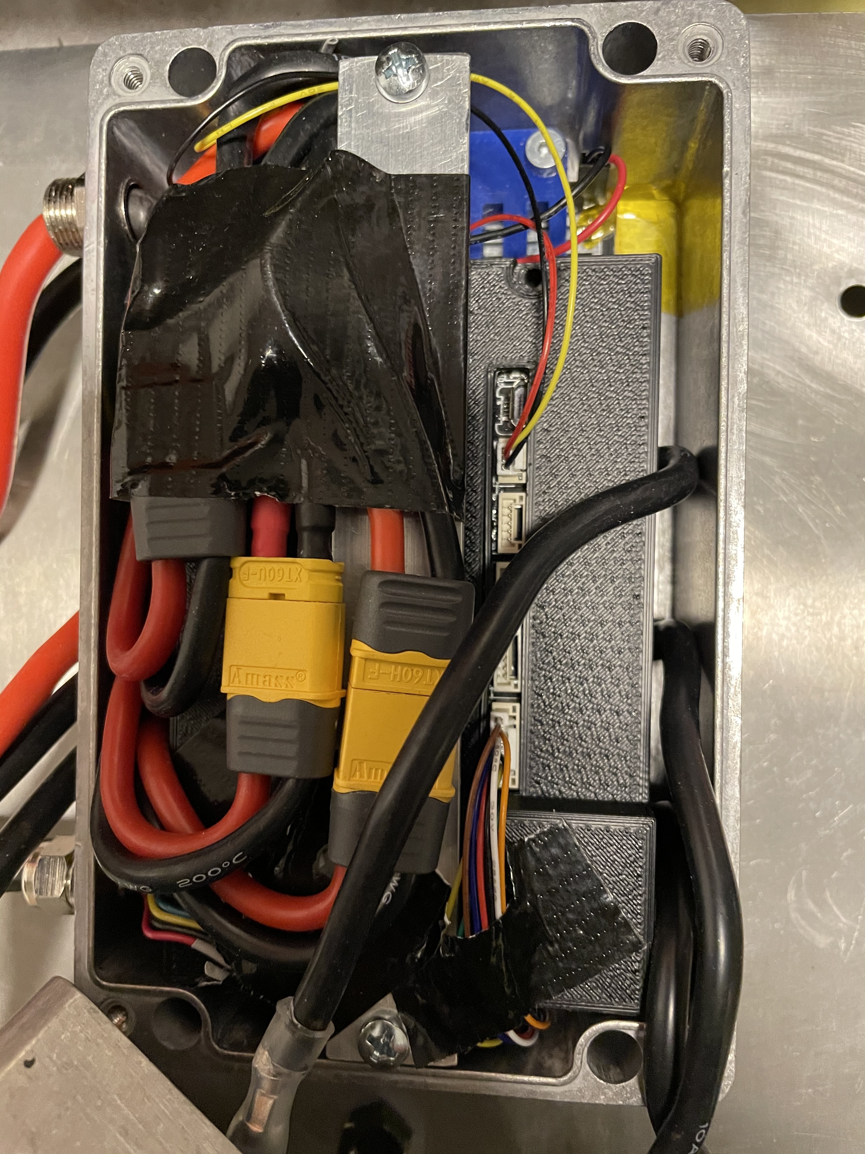

Final product.

11 Likes

Nice job documenting all of this! One question I have for you related to this ESC that I haven’t been able to get a straight answer from Flipsky about. Currently I have a Flier 400a ESC and I want to move to this Flipsky 75200. I have 2 battery packs (12s5p each) that run in parallel for 12s10p. These battery packs output 60a each or 120a total. They have XT-90 connectors on them. Can I just attach the battery packs to two of the three connectors on the ESC or do I have to use the pigtail they provide to go from 2 batteries down to one XT-90 connector and then back to 3? I hope that makes sense. I know the Trampa is setup similarly so wondering what everybody does. Thanks!

2 Likes

Thanks! While the traces on the PCB do appear to connect all of the input wires together on the positive and negative sides, connecting just two of the three inputs would cause unnecessary stress on some of the traces. I would only connect the two packs directly to the ESC for some bench testing, but when you start pulling real amps, you should connect it properly. These ESCs are already fragile enough…

That being said, I would not recommend to use the FS Y-cable either. It has an unnecessary bottleneck (the single XT90). I would probably make a cable harness that connect two XT90 connectors to the three ESC inputs. You could make a very short XT90 block as well.

Personally, I’ll run connections from Amphenol connectors in my battery case with 6AWG cable. I’ll then have three XT90 connectors in the end of that 6AWG, close together, side by side.

3 Likes

Perfect! This is what I thought so glad to hear you think the same. I emailed back and forth with Flipsky and couldn’t get good info from them. Thanks for this!

1 Like

I also now noticed that the XT90 input leads have some questionable solder joints. Easily fixed with some flux and additional solder though. The XT90 connectors are nice because there is no heat shrink, just a detachable solder joint cover piece. Therefore the solder joints are easy to inspect.

How are you guys mounting these ESCs to your ESC boxes? I have an aluminium box and I will be cooling the box externally. Therefore I want good heat conductivity between the ESC and the box. Has anyone tried thermally conductive epoxy? Or do you bolt it down and seal the thread somehow so water doesn’t enter the box? I am also considering thermally conductive double sided tape, or a normal silicone heat pad + a 3D printed holder to keep the ESC in place and apply some mounting pressure on it.

Designed and printed a cover from ASA and fixed it inside a box. There is a 0.5mm thermal pad between the VESC heat sink and the box. The box is waterproof with cable glands and a seal in the lid. The scews to fix the box are outside the sealed area. The box is exposed to water. I haven‘t tested it wirh this vesc but a similar setup with a flier ESC did work (until I had a leakage and it burnt).
Edit: mine is the first version that is slightly different and came without cover, just saw you got the newer one. They are quite similar though I think the lower part with the mosfets are identical.

2 Likes

Thanks for the suggestion! I’ll probably go for 3D printed hold-down clamp & thermal pad or simply some thermally conductive double sided tape. I’ll need to test how the tape likes mineral oil…

I would just use a good :money_mouth_face: conductive pad on the whole under PCB.
Covering the whole thing since those traces and shunts will also develop quite some heat. About the 3D printed case, I would just keep using the ALU case and make sure to have a flat and blank aluminum underside. That aluminum bottom of the case is not the bottleneck of the heat transfer. That would be the conductive pad between PCB and case since those are generally very bad at conducting heat. And for a good one, you pay way too much.

The mineral oil is I messy idea but would work, make sure the case is not completely filled so it can slosh around. And don’t rely on glue or tape to hold things in place. Although I think a good pad can remove more heat.

Oh and out of curiosity what FETS are they using?

Thanks for the suggestions! The FETs are IRF7769 directFETs.

On mine it is IRF7759

Wow, interesting. Different components… Need to dig into that a little bit. Do you have the new FSESC75200 with two UARTs?

IMG_20210104_225716~2

No, it is the HGL-TECH 75200 version of the Maker-X A200Sv2 clone. It is the cheaper one with only one uart and just the lower part case, no cover. Power electronics board looks the same though, apart from different FETs.

1 Like

Can this VESC be switched on and off with a button ? Like for example the original Trampa VESC6

no

20 characters ……….

1 Like