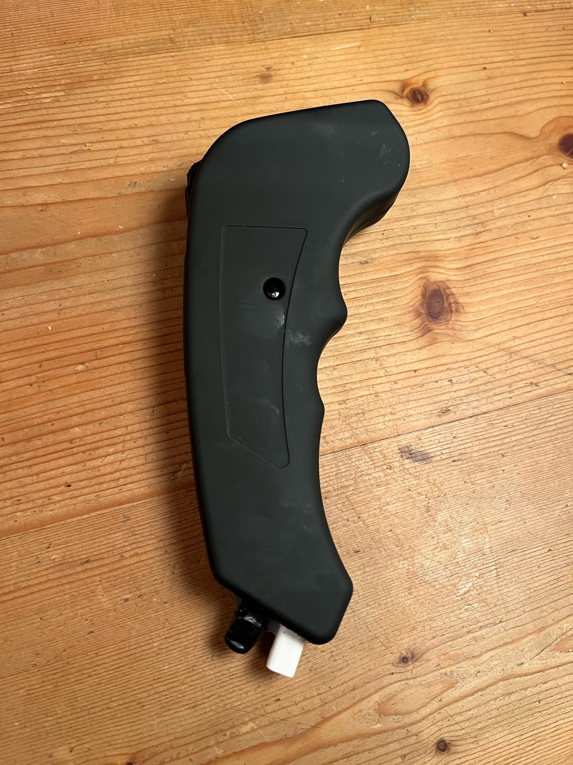
I’ll try waterproofing my Flipsky vx2 remote that i bought but never used so i thought i’d describe it. I found suprisingly little info on the VX2 here and elsewhere, hope it’s still worth the effort.
First issue: charging doesn’t seem to be regulated properly, already after 1hr of charging it’s at 4.22V. For the longevity of the battery it should’ve maxed at 4.15 or even 4.1
I’ll leave it on and see if it goes above 4.25, if so, then it’s a dangerous design.
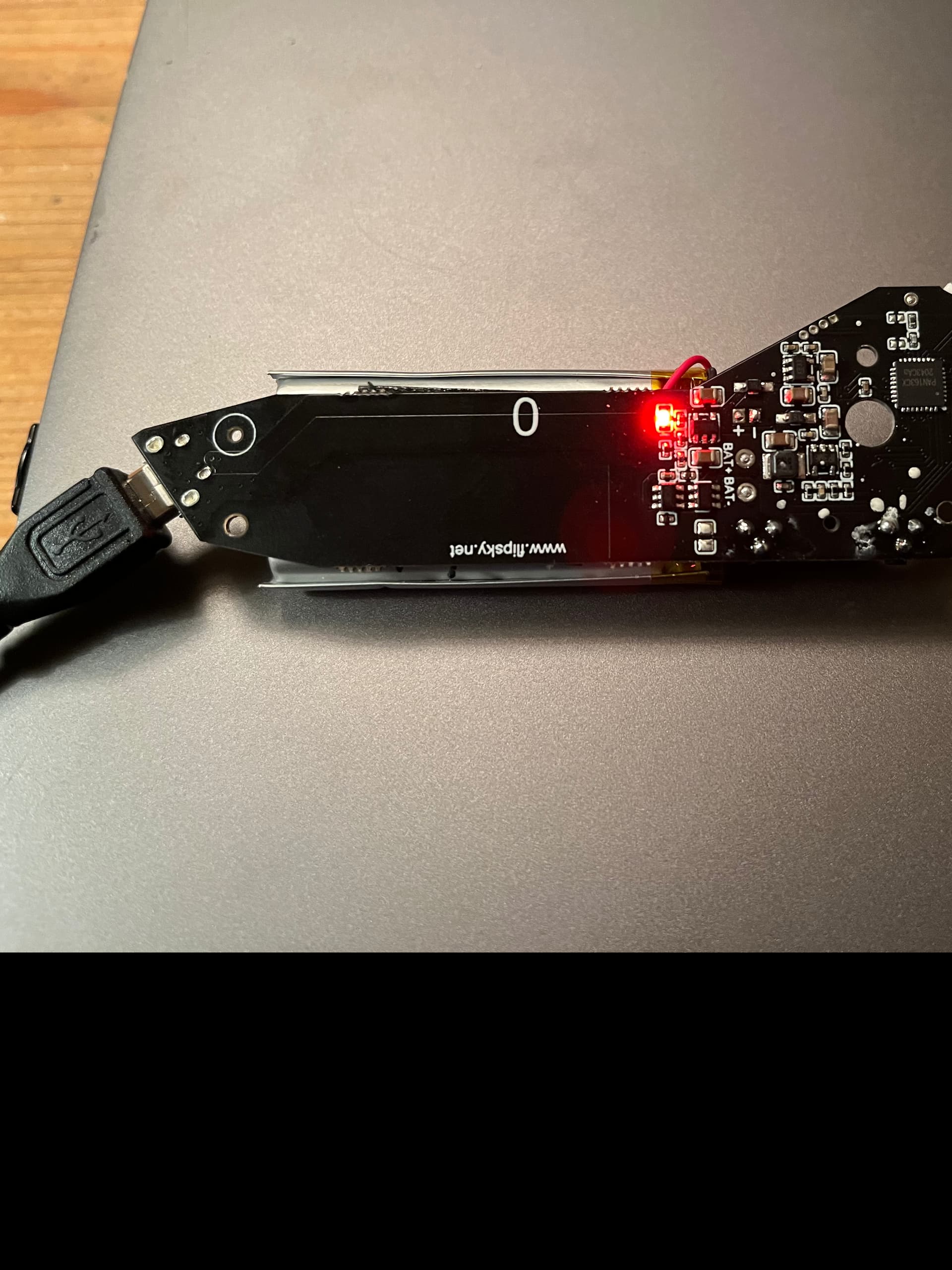
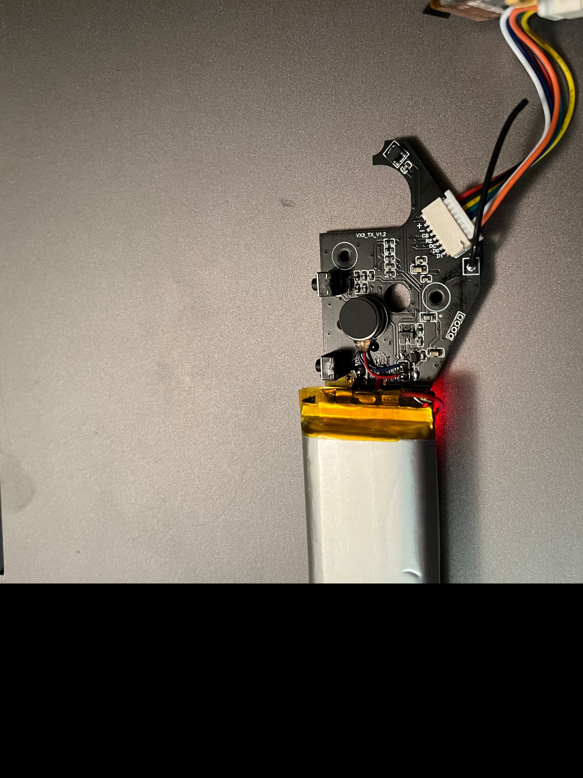
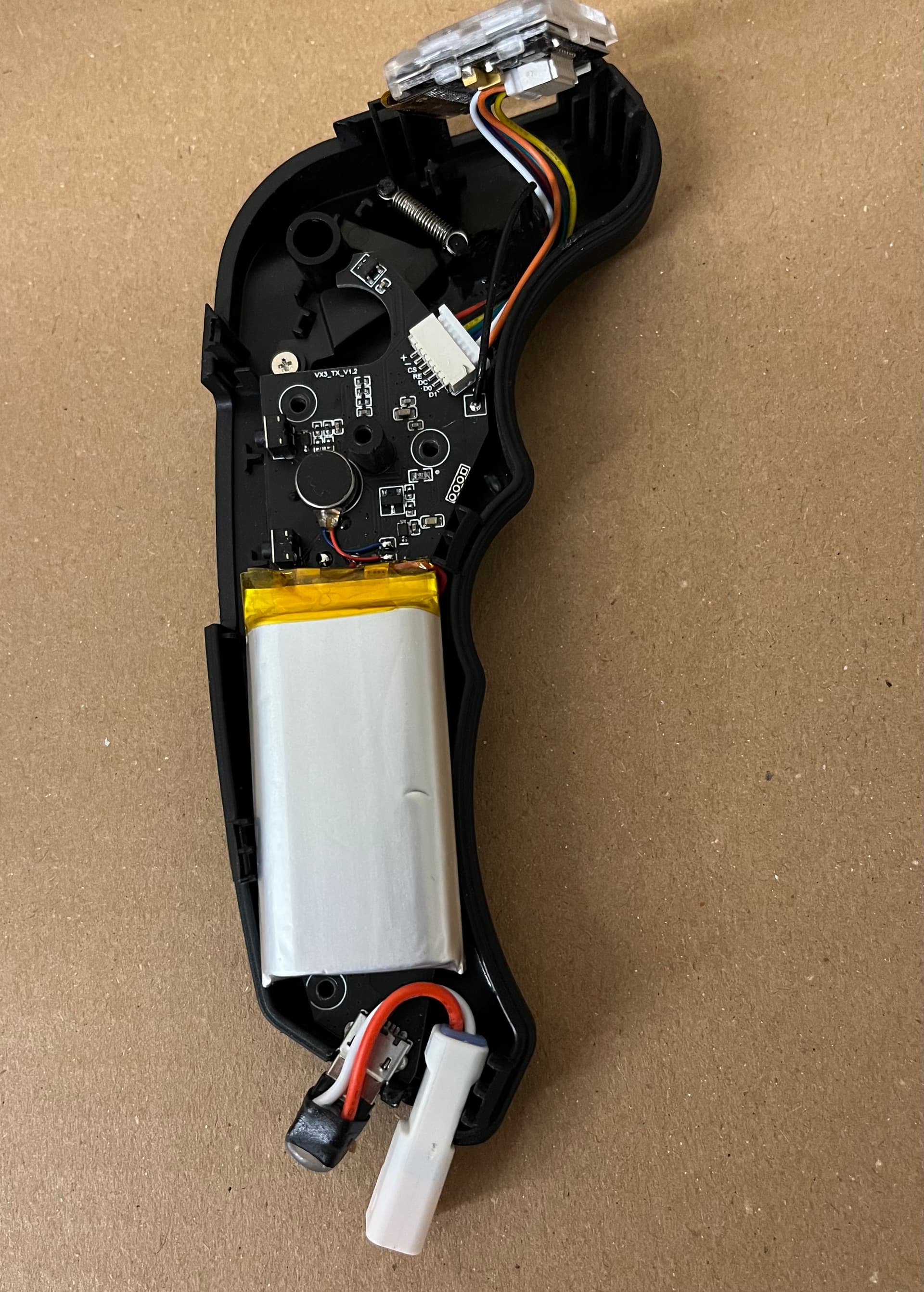
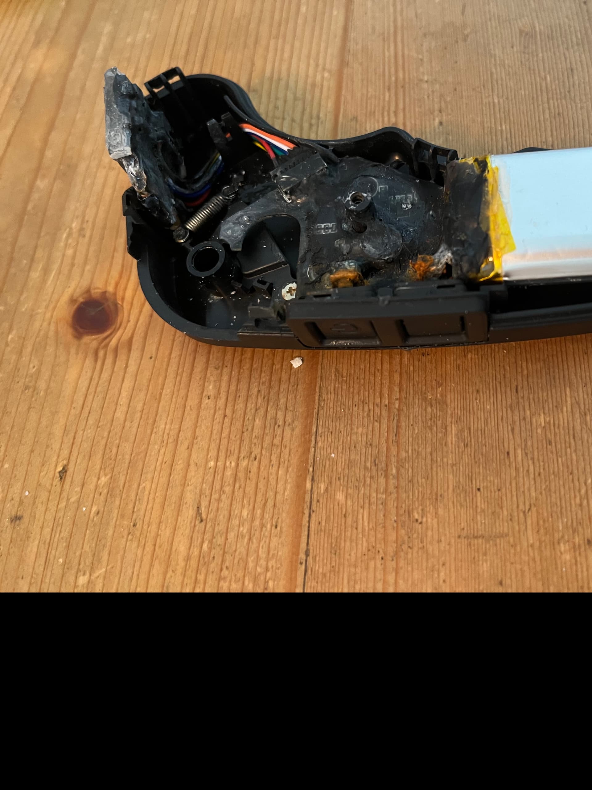
If it doesn’t, then might be worth to waterproof. This is the insides, read on esk8.news that it’s the same pcb as the VX1 remote.
Ok, seems that there is an overvoltage stop, now the charge symbol at the display has turned off and battery is at 4.18V, great!
Now how to get some wires from the micro usb to a waterproof connector? I don’t see any other points to connect to and the back pins on the USB connector are too small pitch for me to solder.
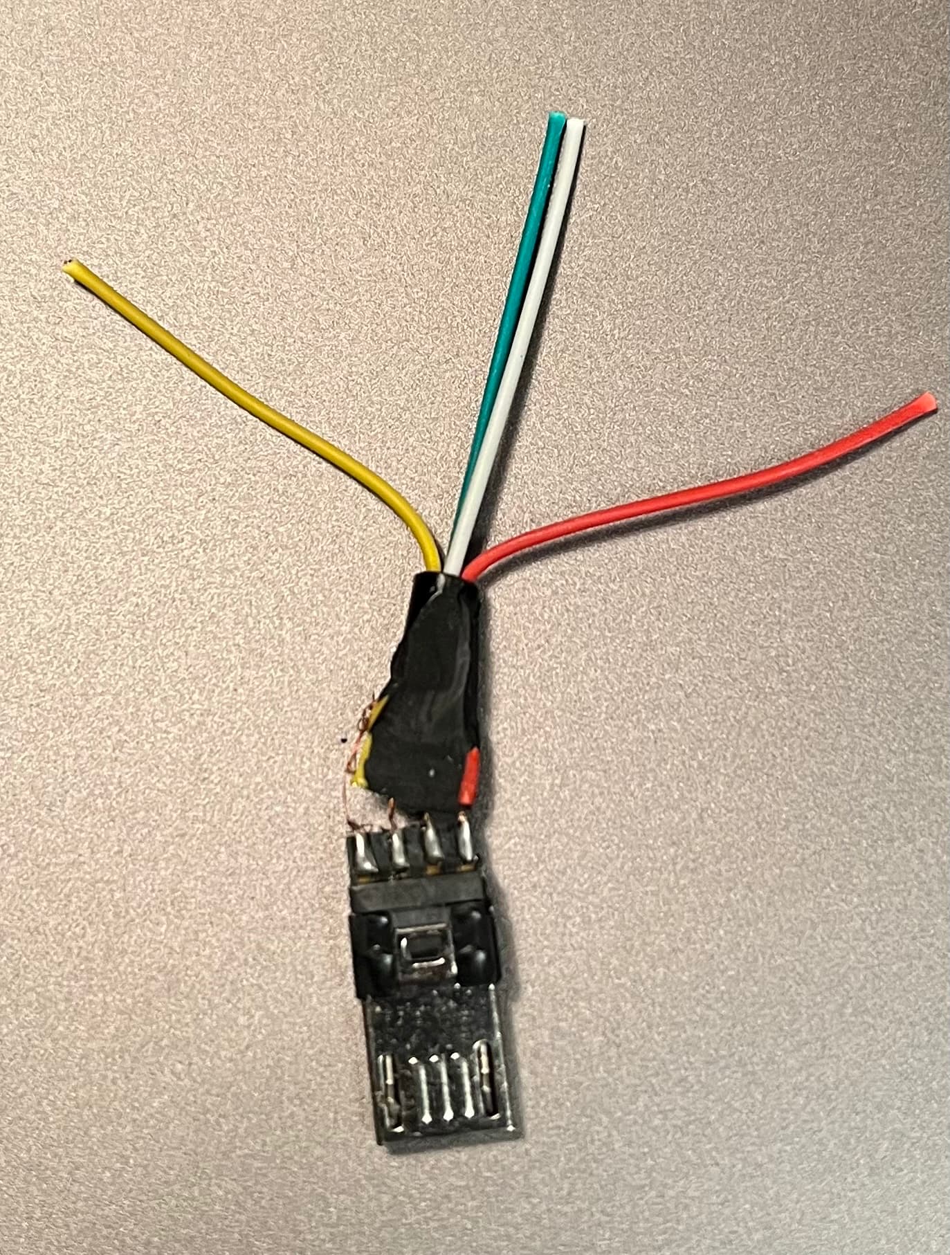
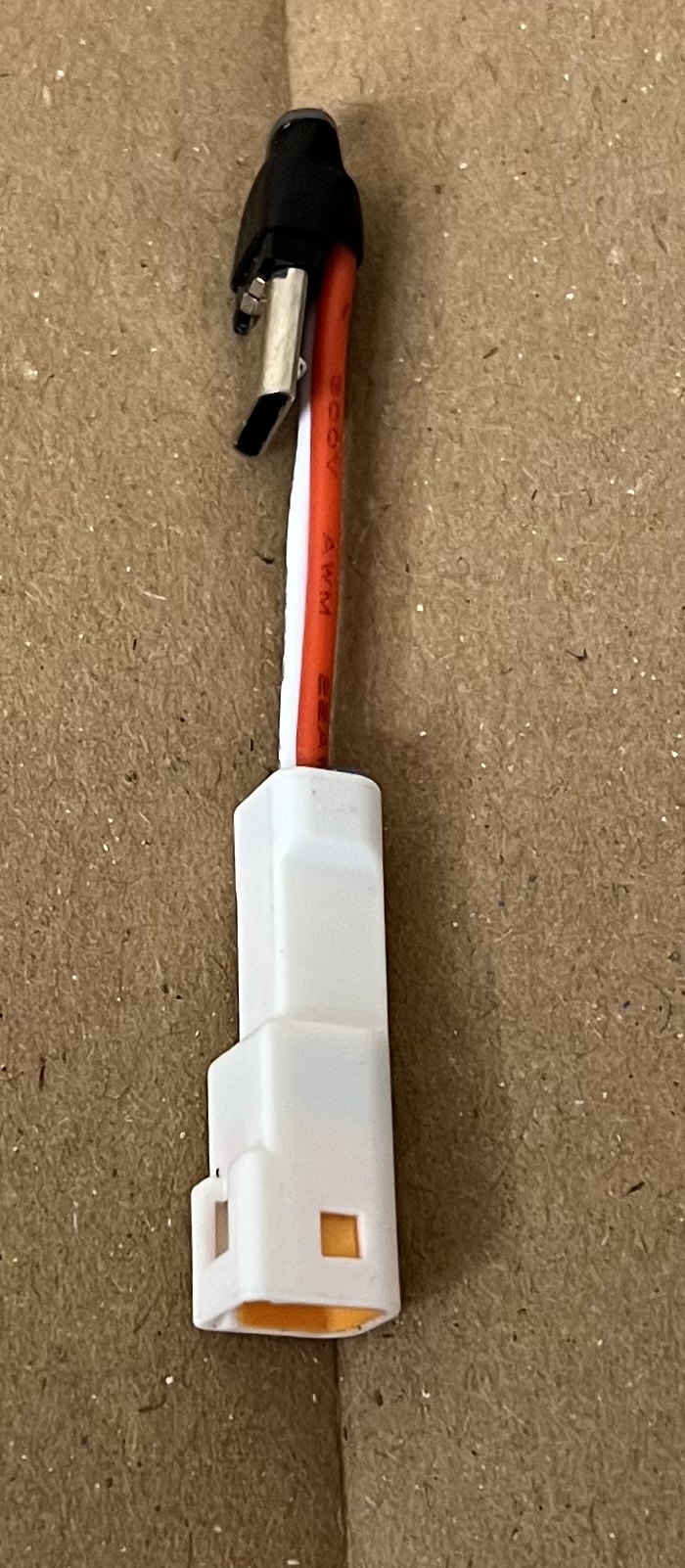
I cut off the micro USB male plug that was included with the remote, stripped the overmolding and made an adapter to a two pin waterproof JWPF connector.
The charge plug is sealed by mating a connector plug (filled with hot glue) when not charging. I don’t have any left, the final one went to the charge cable so i can’t show it but the female plug only protrudes 5mm, the JWPF connectors are tiny.
However, i made a big mistake when i soldered the usb charge connector: it dropped from the third hand clamp, i put it back in what i thought was the same direction, soldered the wires and…
Polarity was opposite on the connector😕
I eventually tried charging, and that was the end of the remote
I’m happy with the waterproofing though, tested before the charge attempt in a jar with water and two tablespoons of salt in it. No issues so it would’ve been nice to test it with my board…
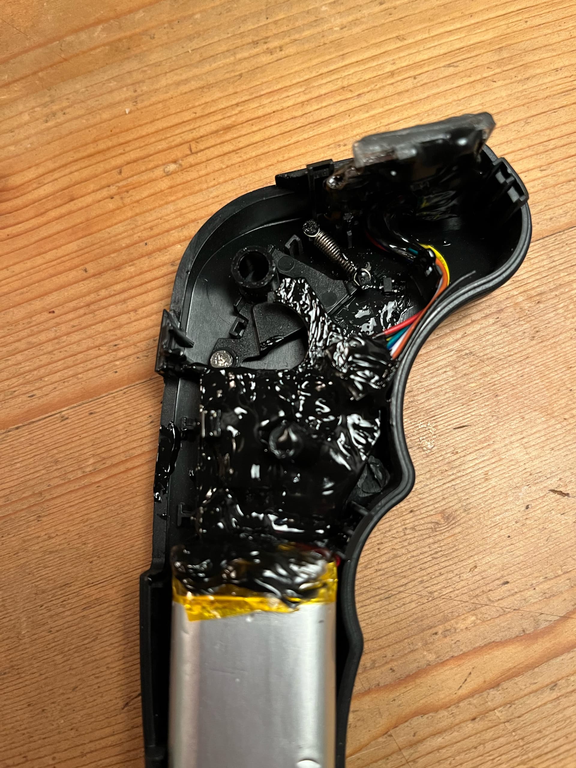
Some tips on the waterproofing:
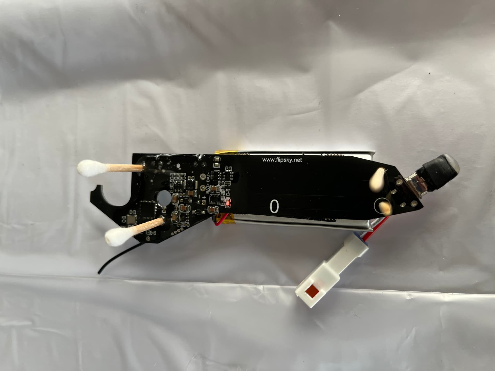
Be careful with the holes and sealant added thickness on the rear of the board. I had to force the PCB onto the keeping posts (even though holes were open) - which worked since the epoxy was still soft when i did it. If the board tilts only very slightly then the thumbwheel will grind against the hall sensor for the throttle. PCB needs to lie completely flat when assembled
The display has a tight fit in slots and the display ribbon film is not protected but grinds on the slots while assembling. Be very careful and don’t force the display in place as you might damage the film. It would be a good idea to put a layer of electrical tape on the ribbon film before pressing display into place.
I opened the remote which has been sitting in the salt water for some days now. It’s obvious that the buttons for ON/OFF and MODE are a weak point for the waterproofing, they already have severe corrosion, i guess this is driven by the voltage difference on the internal contacs
I didn’t dare to put liquid electrical tape on them since i was worried they would get locked.
I think a thin layer of liquid tape plus a spray of corrosion x would probably have worked out on short term but i doubt that this is a working solution over time. Hall sensor switches or waterproof micro switches would’ve been better.
For me the conclusion is that since this is not really a cheap remote it’s not worth the trouble to waterproof it - too much work, not foolproof result.