Ah yeah, true. Okay, so we need to iterate further on that 
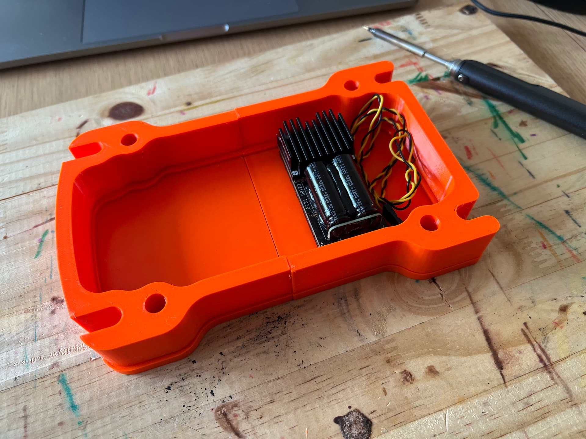
moving on with my upcoming complete board integration.
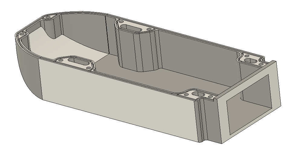
there is A LOT of space under the mast. walls are 7mm. This is likely very strong in PA12.
5 Likes
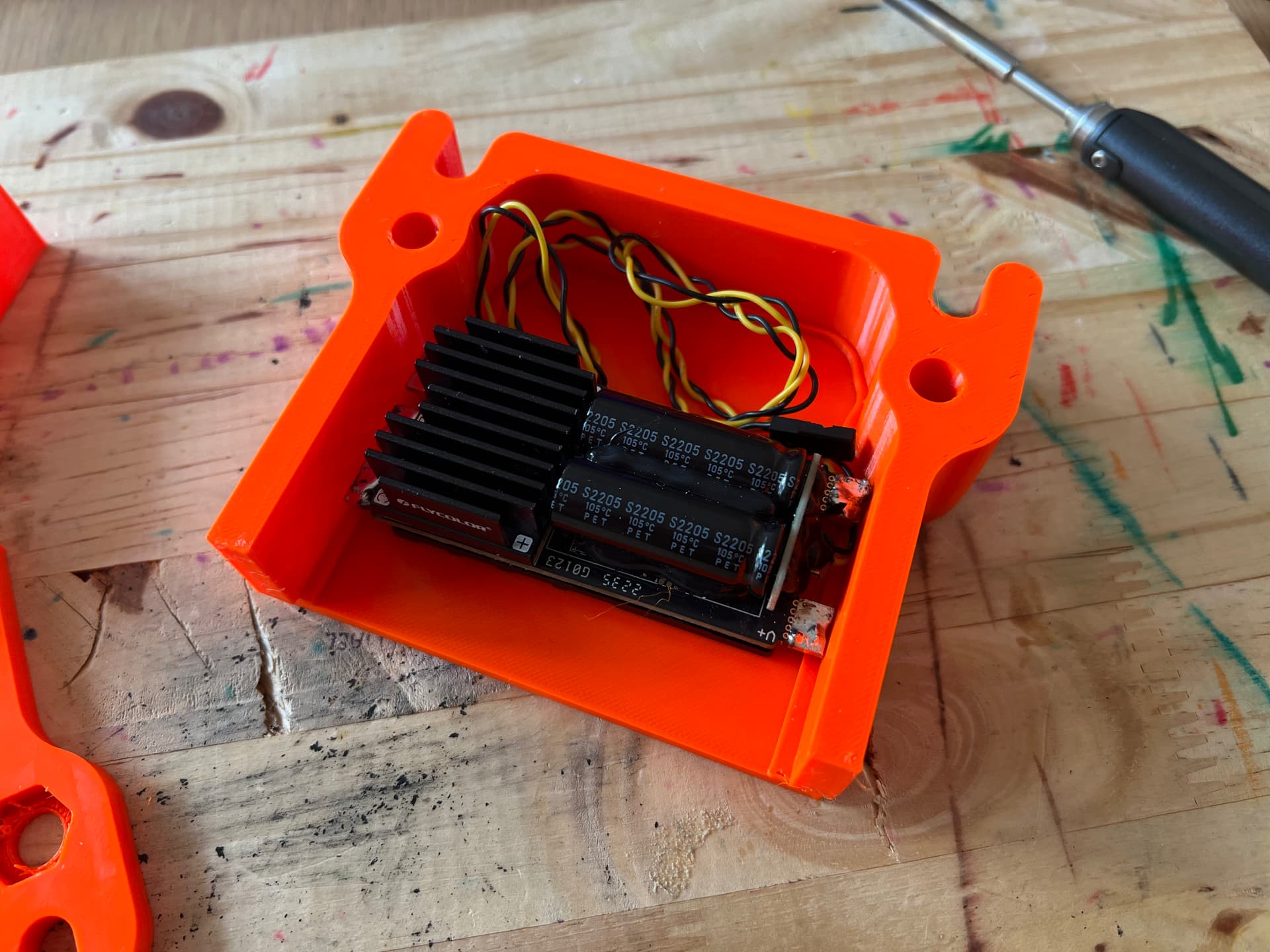
Is that the only heatsink you run on the esc and it doesn’t overheat?
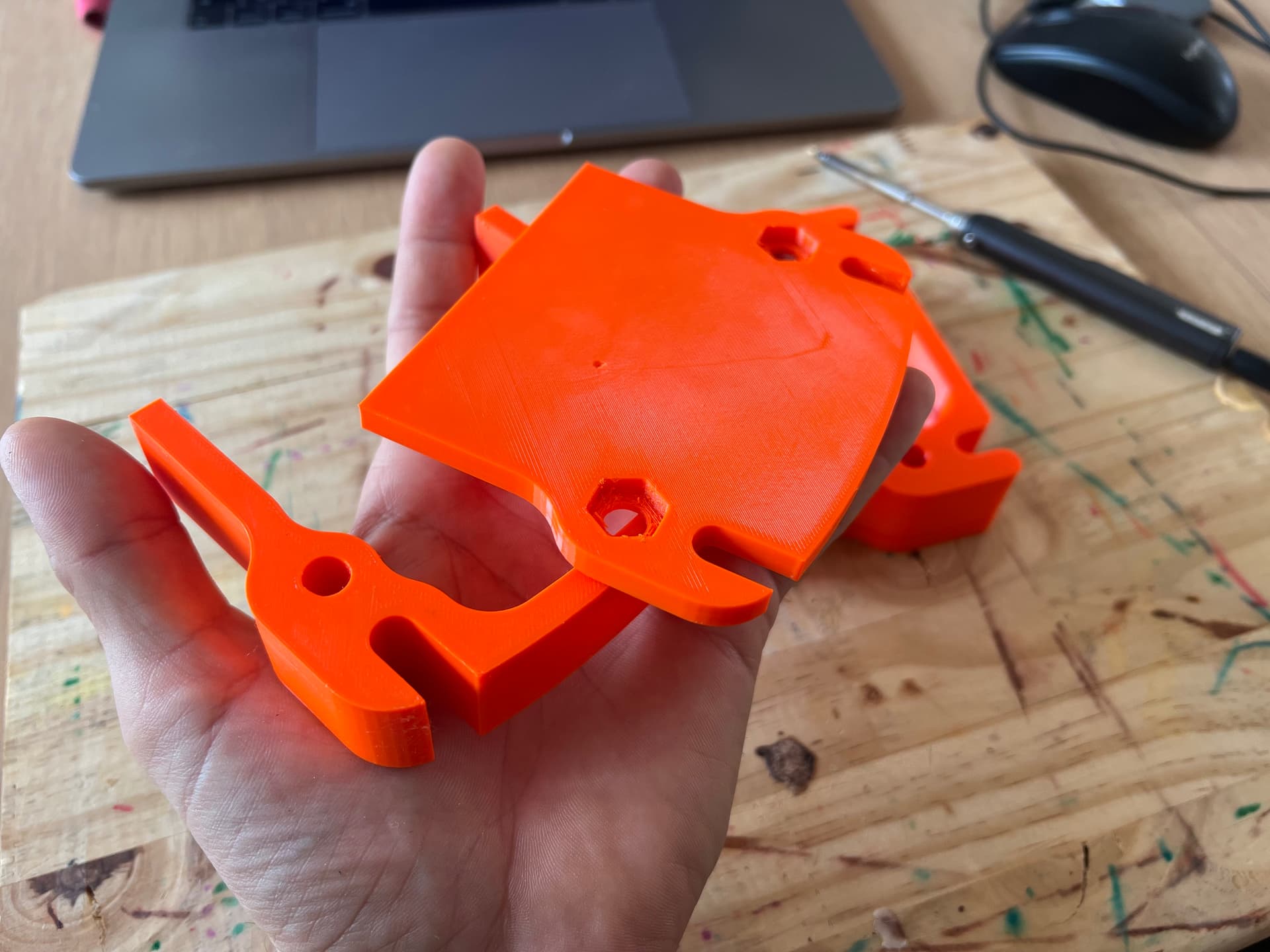
This is where having a large printer is handy, you can prototype single pieces…
yes, agreed with the large printer. I have a bigger one but this Prusa mini plus is so dope and make clean prints that I’ve put my CR 10S custom aside.
the main dissipator is on the other side of the ESC. a super large thermal dissipator.
I could go for a top aluminium plate but I don’t think it’s so much needed knowing that the box will be always cooled down by the mast.
I’ll go fancy because it’s cheap in PA12 MJF but I’m sure the PETG version will already work perfectly
2 Likes
This looks fantastic! Great job. I’ll be looking forward to your next posts as it all comes together.
1 Like
Really curious about this aspect. About to try running it in the enclosure without any cooling; hoping a 100x100 heat sink sitting in direct contact has enough heat dissipation through the wall of the enclosure to remove any need to cut/externally mount it. Fingers crossed!
Does the 12s1P setup at 44V reduce thermal dissipation (half the current/resisitive load) relative to a 6s2p at 22V?
We could start by our kitchens, the airtight coffe pot mecanism (rectangular or round) could be recovered and reused on a reprinted FDA waterproof box
Needs a bit of tweaking to be more flush.
2 Likes
This is already good, does no one has a good CNC were we could do some samples for us in the group? I would definately order one as I think it`s the way to go!
I have multiple CNC’s, but it costs a lot of money and time to get to a good prototype. By that stage it’s almost worth going commercial… Then life also gets in the way when you have kids etc…
Then once you have a design which has cost money to develop, guys want it cheap or free…
Ultimately there’s for to be a balance somewhere…
1 Like
Ok but maybe there is another one in this forum who could do 10 or 20 such cases just for this community profit free. We don`t wanna make it commercial just keep it DIY…
Could also use a commercial service like PCBWay?
Hi Jezza What country are you located ?
Spark
United Kingdom …(20 char)
Once the prototype is solid and complete you could, but before you’ve reached a certain point you can’t. In fact I know better and mass manufacturers in China already, but you still want a prototype that’s not going to leak etc…
I am located in Australia
are you interested in having a conversation off line
Cheers
1 Like
I got so inspired by the Gen2 FD that I decided to build my own version of it! 
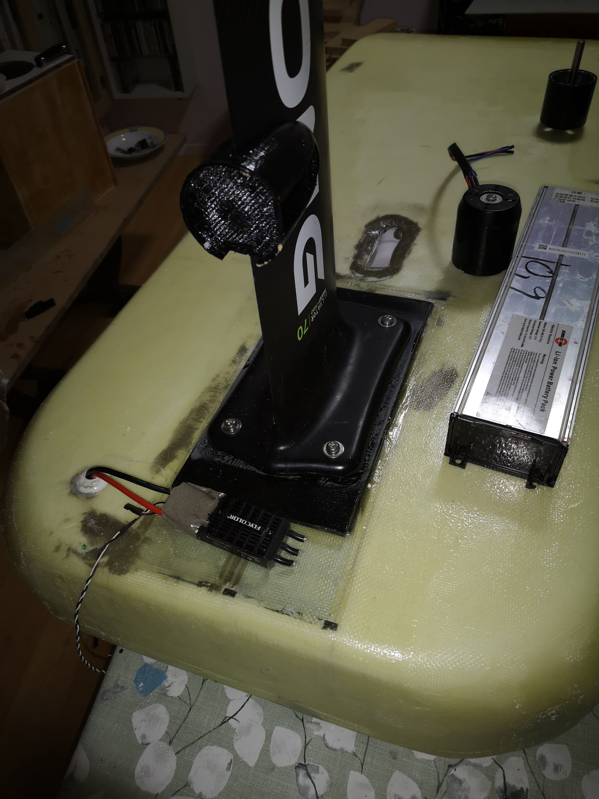
Basically it is two alu-case 10S scooter batteries of total 800wh (usable). Had to use two to get enough amperes, 50A /80A cont/burst. Just glued inside the board for waterproofness and a base for the foil mount made of FR4 sheets. Hope to never replace it, although possible with surgery from the back. Its not super light as it is build to last.
As picture shows I plan to use Flydragon 80A with 6384 120kv,with stock 16 AWG wires for simplicity and less drag behind mast. It is a pure foil assist board for wave use, with motor about 15cm below and skipping on top of water for short stretches. The question is: Will it work to use a slightly potted ESC mounted behind mast, which will get sporadic cooling from dipping into the water?
If run in salt water it needs to be 100% waterproof. One drop of saltwater on a FET is enough to kill the ESC. I burnt too many (V)ESCs…
1 Like
Yes, I’ve experienced that with a “waterproof” ESC that blew up after first test in salt water, which I guess got some tiny amounts of saltwater into it (got some creep voltage too which might have helped the blowup). In this case it wil be underwater and I use a BMS in a waterproof compartment on the deck, so it shouldn’t be a spectacular blowup and costwise it’s not a big deal.
Time to 3D print and see how it feels to hand… I’ve gone 5mm taller than the FD Max as I’m not using aluminium and need extra wall space for strength.
6 Likes
very nice mate. do you plan to make the front section removable with several M4 screws ? We may not need a special latch here, just M4 screws.
We can still integrate an aluminium square using 3M 5200 that will enable to cool a flat area such as the ESC (I believe this is what you did on the rear part, vertically)
The waterproof joint is really nice work. I don’t believe we’ll open that part so much often, so you could even go for a flat area that will be stuck with 3M 5200.
Seems the thickness of the FD MAX is 55mm. I believe it’s a lot… a 2P pack on 21700 will go at 42mm; so maybe 45mm is a good height.