Ah ok. Thank you for the clarification.
I would like to use some calculator that could help us compare, given the same prop and motor, different voltages, also giving the motor phase current, as that is a killer of esc and phase wires on overloaded setups.
wonder if any of the airplane sims can be adapted.
http://www.drivecalc.de/
OR
I think your data is skewed somehow, look here:
I think the root cause is the current data. Something in data is mixed from different sources. Either battery voltage was not the same, prop not the same or conditions not the same. You could upload the logs to clarify, pretty sure there’ll be something there.
Na, its just the rounding on the voltage drop on the for 10S pack… If I remove the rounding then it adds the extra 2.666667W that you see at Pbatt effective:
What i mean is that the theoretic voltage we defined at 4.2V and the current of 60/80A probably don’t match and therefore the results get skewed. Or there was a different load somehow
Reason i think this is that to perform the same task with the same motor and prop would require the same mechanical power, logically since the load is the same (drag at lift speed)
Where would the 340w, 13% efficiency loss then be? It’s not likely in the motor losses (resistance, eddy currents, friction) since the motor has to perform same task.
That leaves two basic options, losses inside the esc or losses from worse motor control.
Inside the esc and it’s resistance losses? It is too large, 340W is a huge heating in relation to the currents and resistance in the esc.
Motor control? It’s only 20% more voltage, switching frequency is the same. To actually be a loss means the applied current needs to reach the coils at the wrong time vs the rotor position or are spiking out of control. Spiking would be more likely at higher voltages, right? (=advantage 10s system)
Other losses?
You require the same thrust at the prop at different battery sizes in order to achieve
board plane speed or foil stall speed. But with different voltages that comes at different battery power.
eg…
Say I was to ride using the same power of 3018kw in both systems. That means with all the voltage drops etc I see the following (with a 3D printed prop I have assumed a lower efficiency):
Now if I reduce my speed on the 12S system to match the speed at 10S I use less power on the 12S system.
I am running an inefficient 3D printed prop so I assume it makes things worse than what you’d see with properly matched efficient props.
My FR blades arrived today so hopefully I can get the hub cut ASAP and then get some new test data…
Rpm at prop is measured or calculated above?
The noload rpm will be higher on 12s but loaded rpm can’t be calculated and used like you propose since the motor might not be capable of reaching a higher rpm. This is due to the need for increased torque, current and power at higher rpm. Scaling down from a higher rpm is equivalent of reducing the duty cycle and that is already accounted for in the difference in battery current.
Looking forward to some data on the behaviour. With logs!
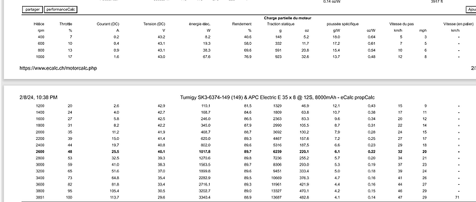
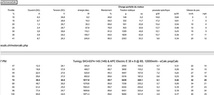
Hello, in order to get more info and understand more props things I got ecalc membership, allows to check for partial throttle. 8S3P at 72% duty cycle/Trottle 2600RPM is exactly equivalent to 12S2P at 48% duty cycle and 2600 RPM. same efficiency from the motor. 12S allows much higher max power.
phase currents are not calculated by the tool.
both say 16 minutes of motor at this power level.
when a smaller diameter and higher pitch is used on 12s, static trust at 1000W is similar but efficicency is 2% higher. not sure 2% is sinificative?!
Great effort!
2% is not really significant for the total, if it would be heating in a critical component then yes but here it’s in a motor with excellent cooling.
What does ecalc cost? Never used it.
Waiting for the data, looking forward to seeing the verdict on this one😊
Gonna have to wait a bit longer. Got everything read and put my back out lifting a CNC gantry…
Ouch! I gotta move mine to make room for some family stuff. Been dreading it.
My Maytech hand controller stopped communicating with the Maytech VESC. After reading some posts, I know other ones are better. But, is there a way to fix my problem with this one? It’s been working great until yesterday.
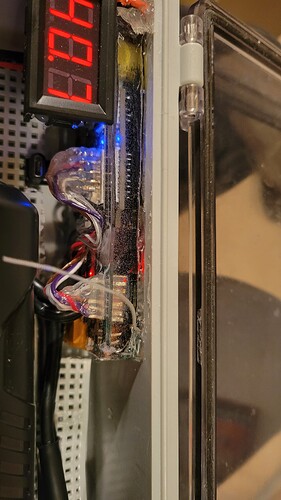
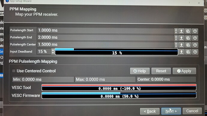
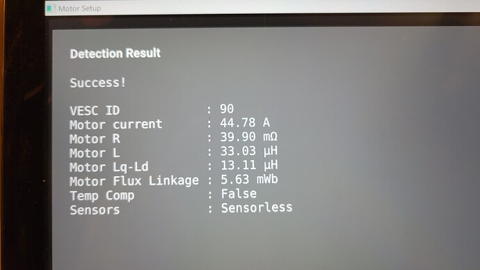
It started losing signal occasionally.Then it would just go without any trigger–even with the controller off! I held the board on its side until it finally stopped. I finished off the battery without anything else crazy and came home. I hooked it up to the computer, and the controller side of the ESC is not working right. I tried resetting it but now it does nothing when I pull the trigger. I reset the firmware, the motor, and the controller. No go. I’ve attached some pictures.
It’s all potted in epoxy, so I hope it’s not hardware.
Thanks!
if you have uart hooked up, you may try switching to uart vesc remote. I had issues with ppm and uart solved that.
Thanks! I’ll give that switch a try. I’m assuming that I can’t use the Wizard for that setup.
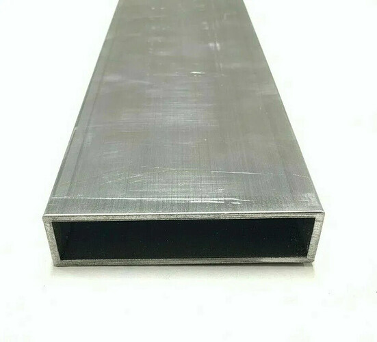
What do you think about building assist using aluminum rectangular hollow profile between board and mast? (Similar to fdgen2, but longer)
It doesn’t have to be waterproofed. Assuming battery, ESC and receiver are properly potted and connector waterproofed.
Hi there,
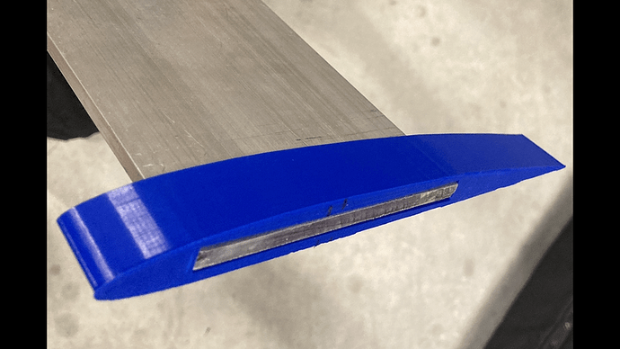
I’ve been playing around with the idea of 3D printing foil profiles that could slide over a piece of aluminium flat bar.
If I find something that works eventually I would like to lay some composite to form the skin.
If you found a profile that fit the width of the battery you could potentially make the aluminium extrusion the mast itself. (With a little hydrodynamic smoothing of course)
You could also have a split mast with the section above the motor aluminium extrusion and below the motor composite for mounting the foil with the least drag. (25cm ally/50-60cm carbon for example)
Housing the esc in the ally extrusion would obviously also make a beautiful heat sink.
I can see this would work best with an assist design.
Cheers mate
If you are interested to put stuff into the mast, there is such a product on the market - called rayfoil.
I also like your idea of putting it beneath the board like the gen 2. ![]()
There is an old build where someone did this way before Foil Drive even thought of it. In fact it may be where they got the idea from…


