Hi, I’ve finished making the first prototype of the adapter. I’m going to create a new thread and share the first pictures of the prototype, all the technical information, and the new drawings of the parts.
I’ll make the “good,” elegant version next week; I don’t have the time right now.
i toyed with that idea of just a plate with the different bolt hole patterns on each side, its one way to do it, but i have a 3d printer and i’m a but OCD on weight and keeping part count minimal, keen to hear how it goes
for anyone printing an adapter like mine definitely just print it on its side as it fails on the layer lines if you print it vertically… if you do that PETG seems perfectly strong enough and its easy as to print, you just need to enable supports to do it on its side
Since I didn’t get a response, I had to solder an adapter and connect it to the Fd v2 myself. And here’s what I found: everything works, the Maytech remote shows battery voltage, and the motors start. I’ll have to weld batteries for my friend using new, high-capacity cells.
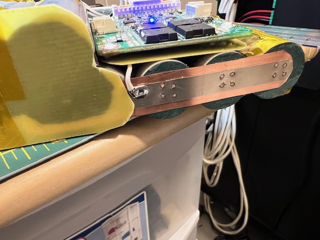
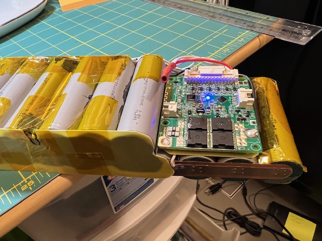
JBD 14S BT bms, BMS is wired for charging only (on the small pin of the XT90i connector). Need to remove the heatsink and trim the plastic of the UART port so it fits in the slanted area of the cone.
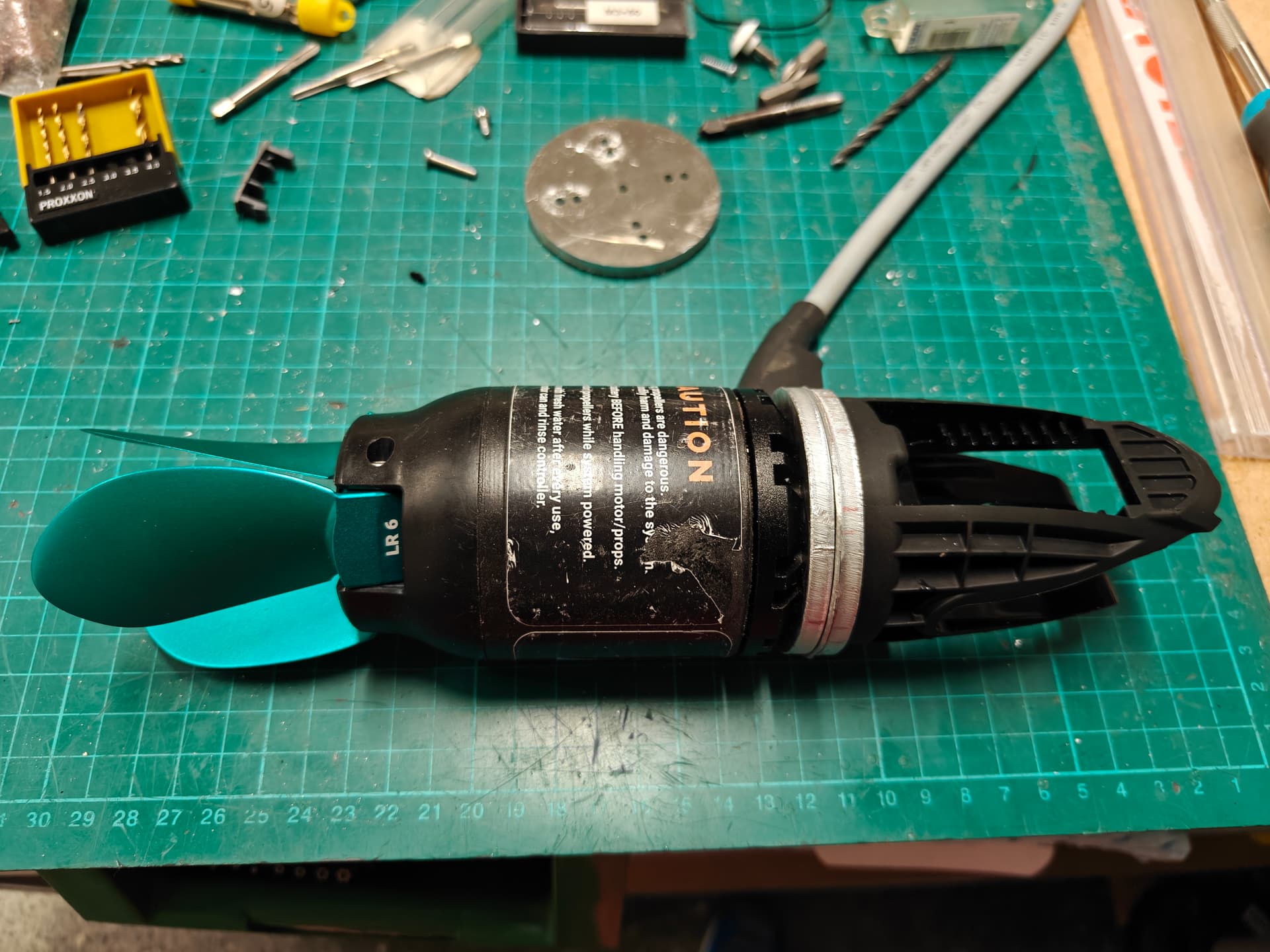
Yeah - genuine FD Max main unit with FD v3 remote and FD HP motor.
I also did a sport battery (11s2p) with RS50 cells that performs really well with 18Wh cells (I see FD just officially launched a sport HP battery).
Next on the list is to build a couple of batteries with the new linkdata 65P cells
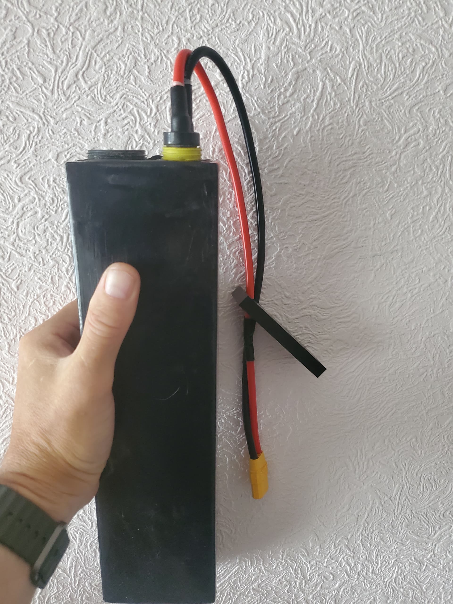
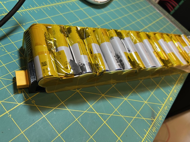
It’s a 10gauge insulated wire that runs long on one side from the back of the battery to the xt90 in the front for negative and a short piece of 10gauge bare copper for the positive. Both soldered to the 0.3copper plate that is spot welded to the cells. Sorry no picture since it is now shrink wrapped.