What are you using as CAD software ? Orings groove are all standardized. I have an option in Inventor that calculate the best Oring / groove combination for my piece. You should have something similar I guess.
1 Like
I use Fusion360.
An o-ring calculator in fusion 360 is not known to me. I have used an online calculator from a website.
Hi.
I would make a longer phase with less degrees because the o-rings seals behind the holes - additional you can optimize your 3d-printed part to center the tube with the longer phase.
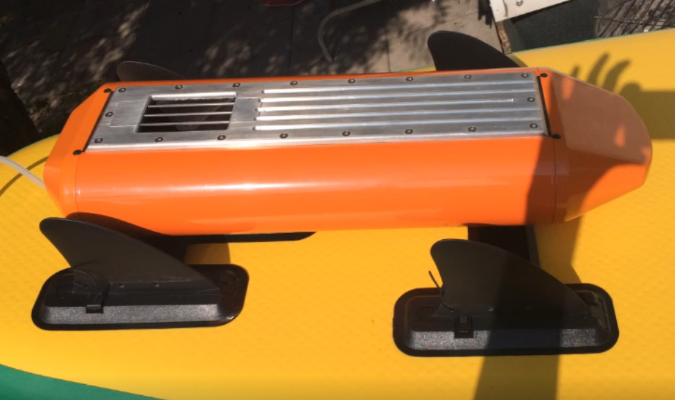
Two years ago I made a jet-drive for a SUP with a MHZ jet - so very similar to yours - I would go to 12S with the 360kv motor to have less amps - at least I have the SSS 56123/360KV with good results.
All the o-ring calculators are based on high preasure - we have very low preasure.
Mike
Do you have your drive still in use? What is the power of your drive respectively what speed will you reach? Did you post your drive in this forum?
Regarding the o-rings: i have just found an online o-ring calculator and found out that my chosen o-ring is wrong. The compression is too high.
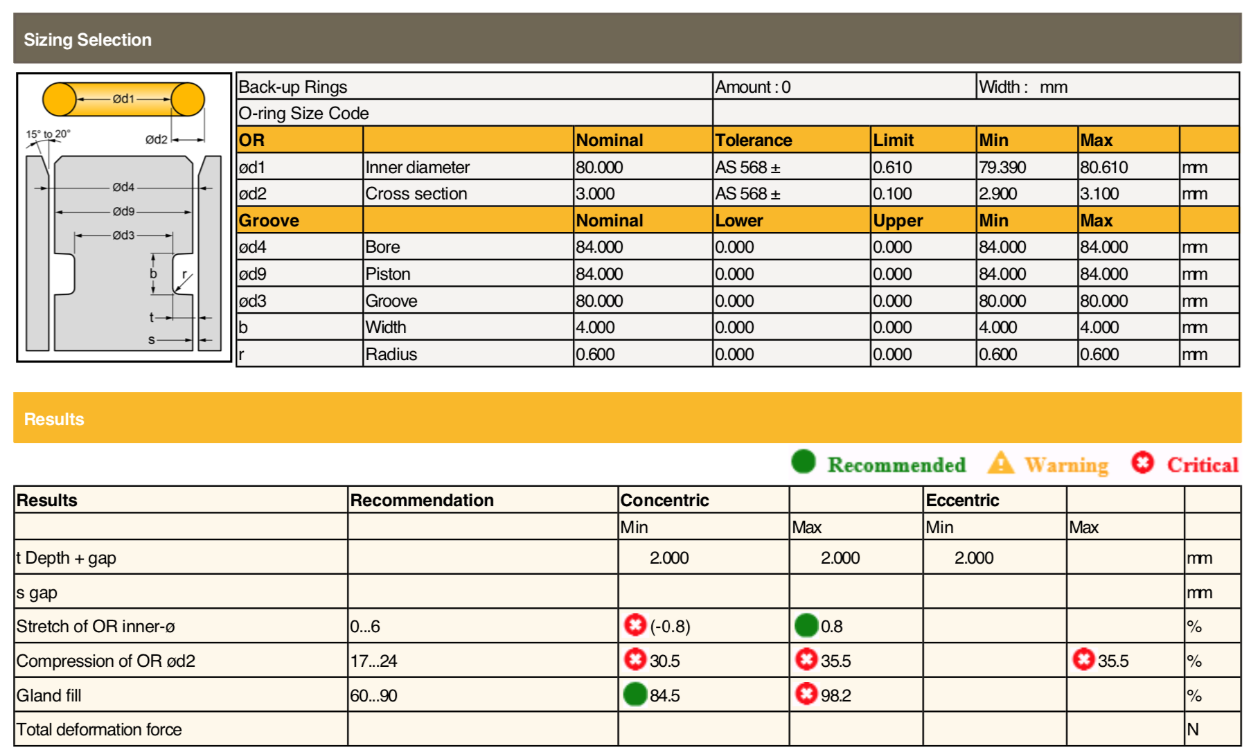
but how do I find the right o-ring for the inner diameter (84mm) of the aluminium tube ?
Does anyone know a calculator where you can enter the diameter of the aluminium pipe and calculate all the required dimensions? (o-ring size, groove,…)
You Send me the data for 3d Print for jet Drive?
Send me your 3D file without the groove. I’ll generate it automatically with the oring on Inventor 2020. I am not into Jet Drive so you can definitely just send the part of the file you want me to modify if you don’t want to share it totally.
It was not a efoil but a motorized SUP:
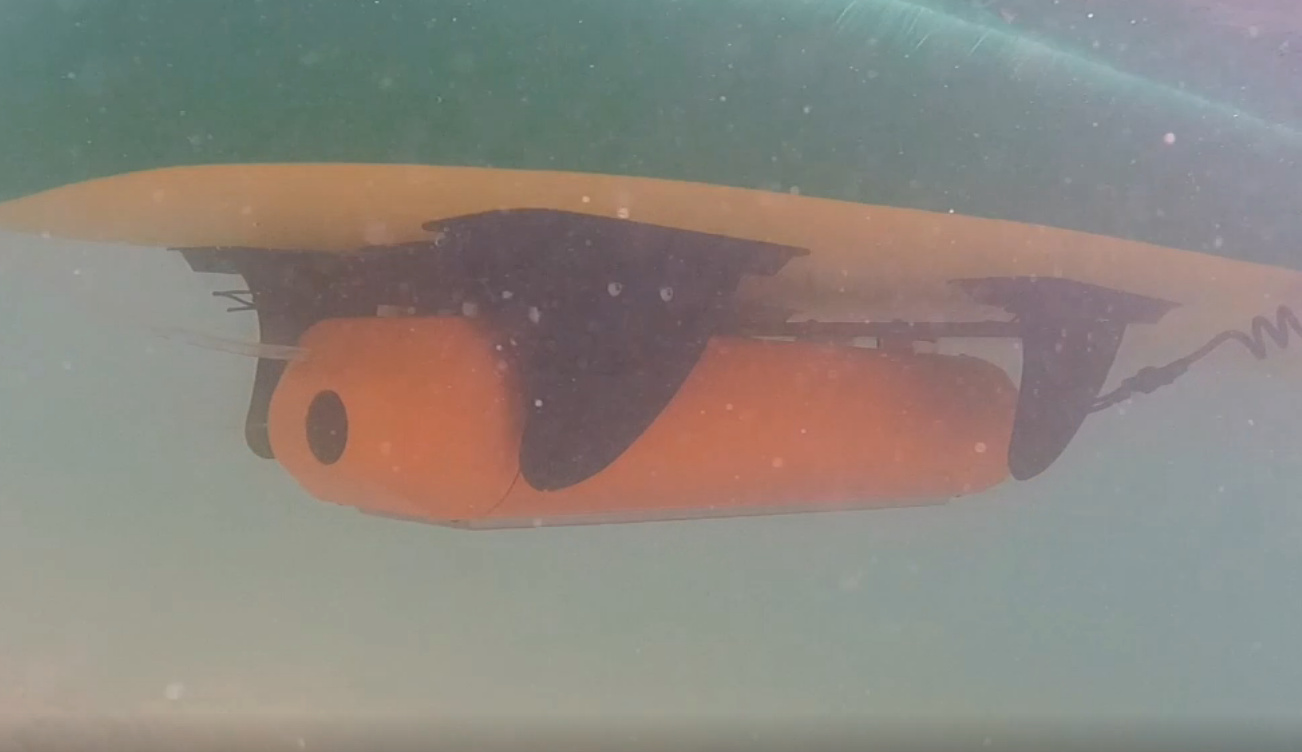
Power at full speed over 100A and therefore not really usable
 and not posted.
You can use this PDF https://static.o-ring.de/or_3.pdf
Take for “Nuttiefe” = dynamisch and for “Nutbreite” = ohne Stützring - allways use grease to mount o-rings - to insert it in the groove and on the surface where it has to slip in.
Interesting construction. What was your approximate speed that you reached?
I think an SUP is not designed for higher speeds and does not glide.
I’m curious how efficient the drive on the windsurfing board will be. After all it is designed for planing and early planing. But I have to reach at least 20km/h for it to glide.
Today at noon I found an app from Trelleborg for Android. (Just enter Trelleborg in the Playstore)
In the app the bore diameter is entered and the matching o-ring and groove is calculated. exactly what i was looking for. I will now test the suggestion from the app.

Max. speed was 16kmh - but with 100amp at 10S not really efficient - all in all nearly 4kw.
A similar construction with outrunner and propeller need less than half.
A electic power SUP or windsurfing board is a nice thing - but believe me, once you are efoiling that’s all you want 
Hey very nice. I also want to build an Jet-drive Foil.
But out of aluminium…
Vowo besch us de Schwiz?
1 Like
Bi vo Pfäffike ZH. Du bisch vo Bern? (for the Englisch readers: I’m from Pfäffikon ZH and you?)
1 Like
Cool, ich aus Stäfa ZH. Habe mehrere Jetsurf Boards gebaut…
2 Likes
Nice. What Jetdrive and motor are you using in this video?
It is a modified MHZ jet with 64mm. The motor is a Lehner TorQstar 7040.
It was one of the first runs with the new and improved setup in Corse. Was a really long way to get the whole setup stable.
1 Like
I more and more want to give the MHZ 64mm Jet a try.
But what Motor and KV for an e-foil? I want to use the Vesc 75/300.
How to atach a trustbaring and the shaft,
Könntest du mir helfen? 
For jet propulsion a high KV motor and for propellers a low KV motor.
Since I am still in the test and optimization phase myself, I cannot yet make any engine KV recommendations.
For a jet drive a thrust ball bearing is not really necessary. The pressure is created at the nozzle of the jet, at the moment the water leaves the nozzle.
However, to be on the safe side, I have installed a double angular contact ball bearing. This can take axial load well.
1 Like
The acutal motor is a 7040/6 so around 280-290 rpm/volt.
I am using LiPo cells in a 14S/1P configuration.
The can handle 300 A continiously (per cells).
15S was bad for the ESC…
If you need more, we can talk it Whatsapp
Some time has passed in which I have continued working on my project. In the meantime I have found the right O-rings and groove combination.
For the final assembly I am still missing two washers and nuts, unfortunately the DIY stores are closed due to corona.
Some parts I have printed again to simplify the maintenance. (easier assembly and disassembly)
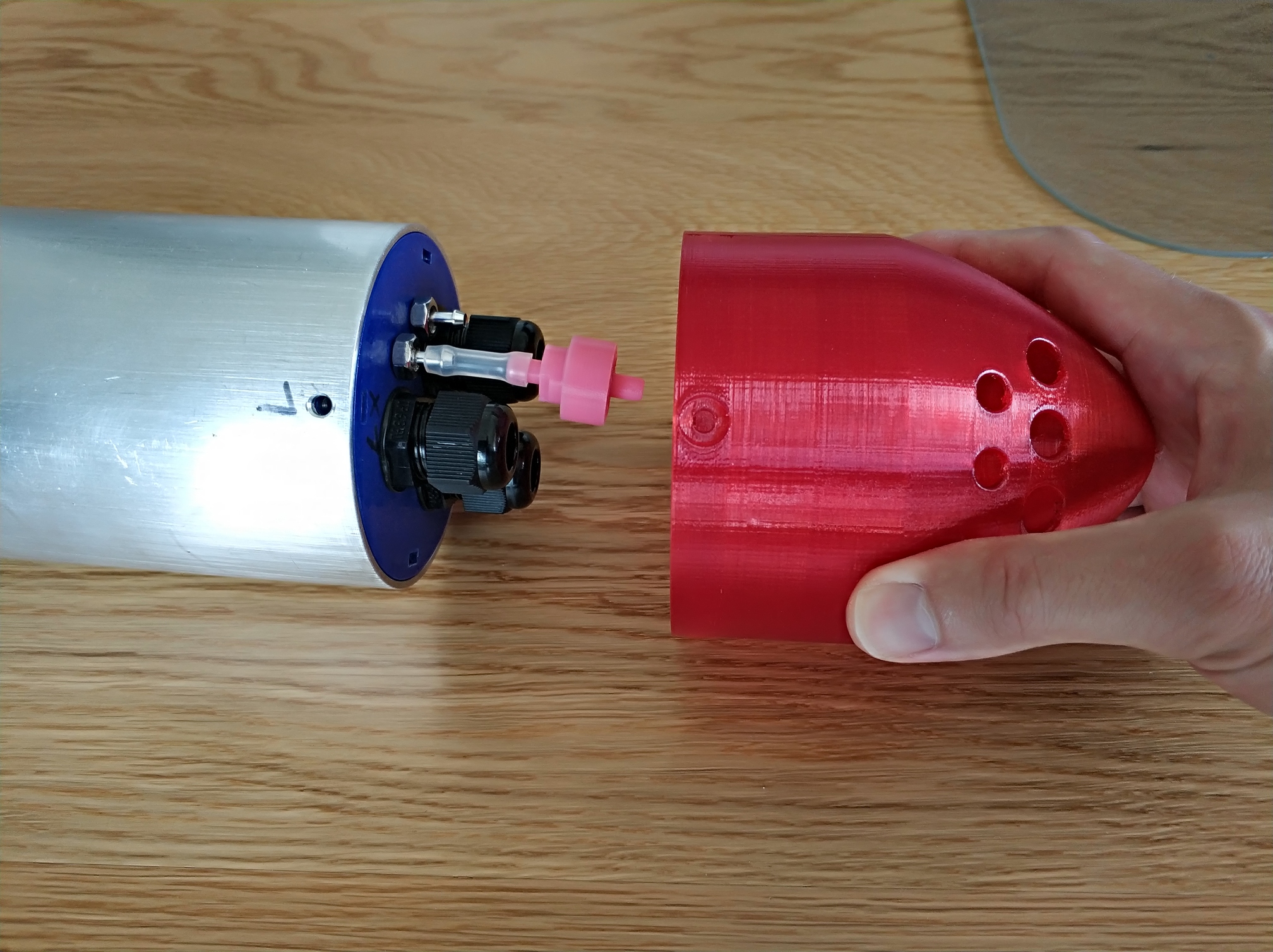
I have built a water filter to prevent dirt from getting into the cooling jacket of the engine. In the video I have tested the filter with a syringe, it is tight. (With a 3d-printed sealing ring from TPE)
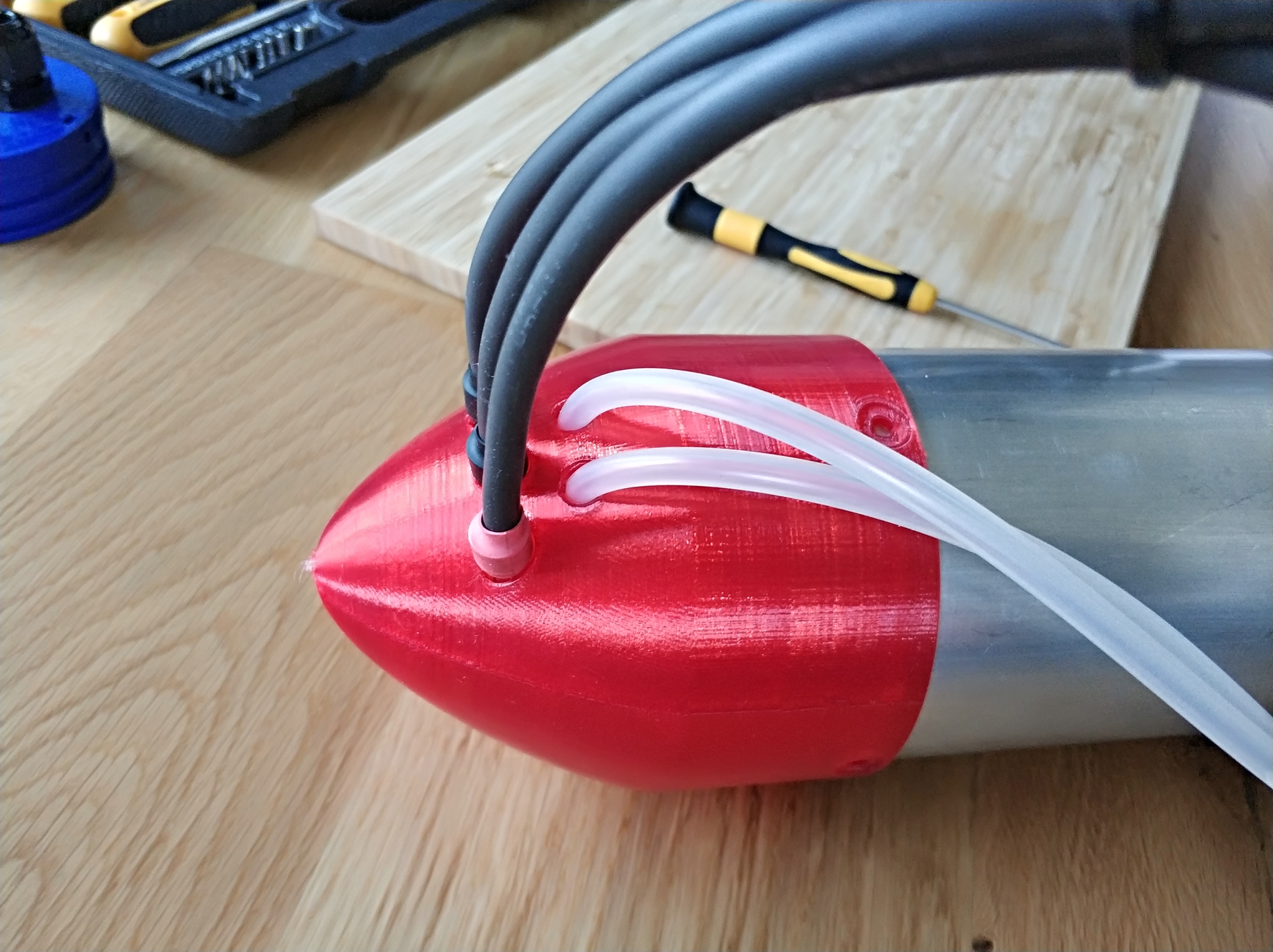
Some pictures:
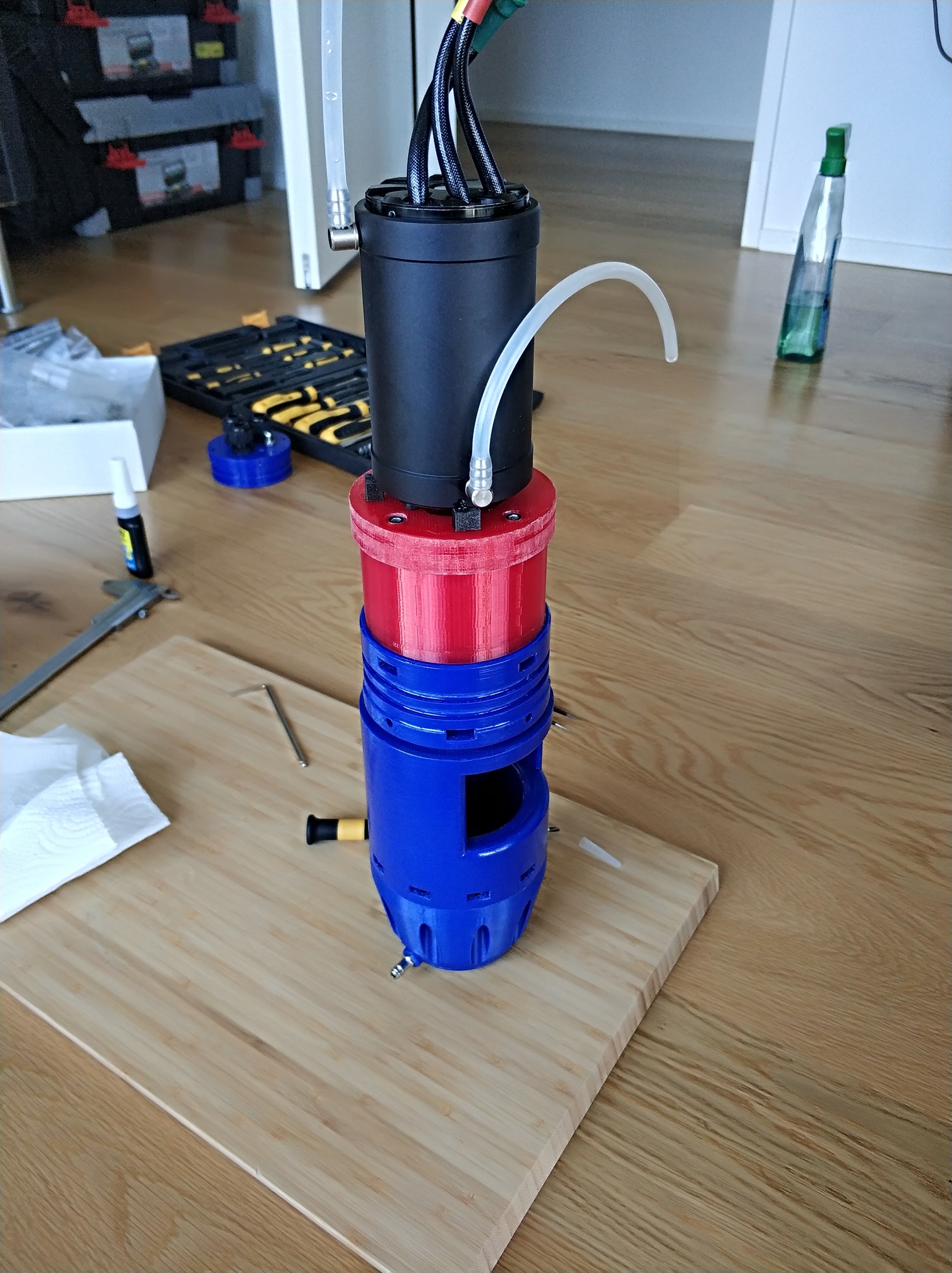
the water filter has space under the cover:
I know the cables and hoses are very bad because of the drag:
3 Likes