McMaster has what you want.
I like the stainless steel 110mm m5. You can go up to 140mm m5 in black oxide.
McMaster has what you want.
I like the stainless steel 110mm m5. You can go up to 140mm m5 in black oxide.
Mcmaster is my favorite.
I want to run in saltwater, so I do not think black oxide would be best.
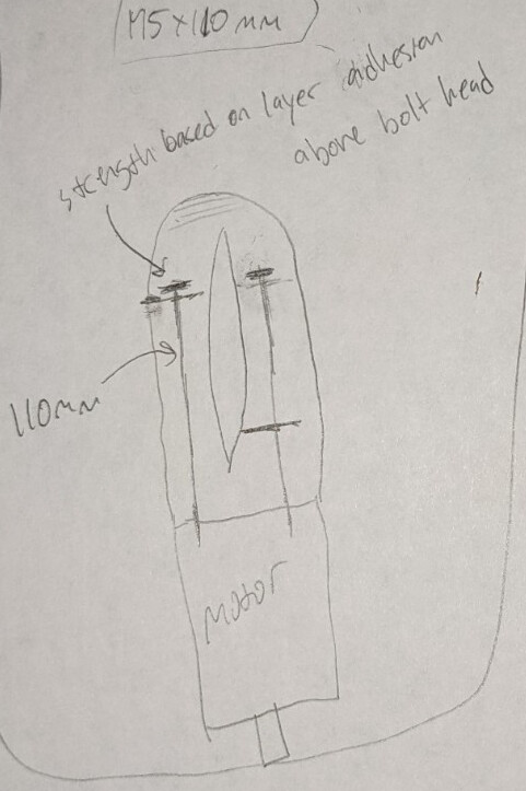
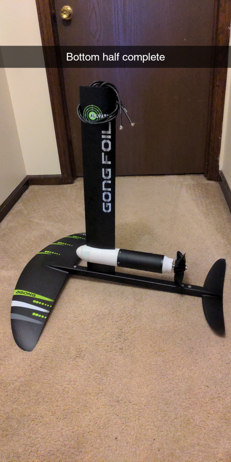
Unfortunately if I use 110mm hardware, I would not be able to use the mast clamp I want to use shown below. The smaller hardware limits how large I can make the “pocket” to route the wires inside this mast clamp.
I also want the hardware to clamp all the printed layers together. In this way the layers are being held by the clamping force of the hardware and not just layer adhesion. I think this will benefit the strength of the clamp greatly.
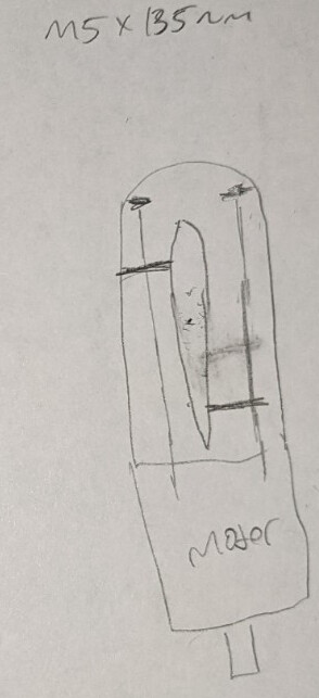
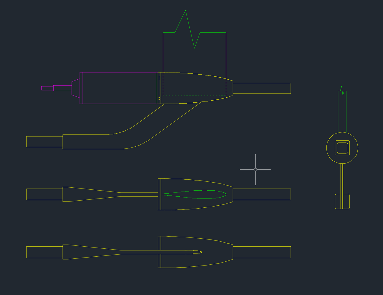
Here are some comparison sketches to see what I mean about clamping all the layers.
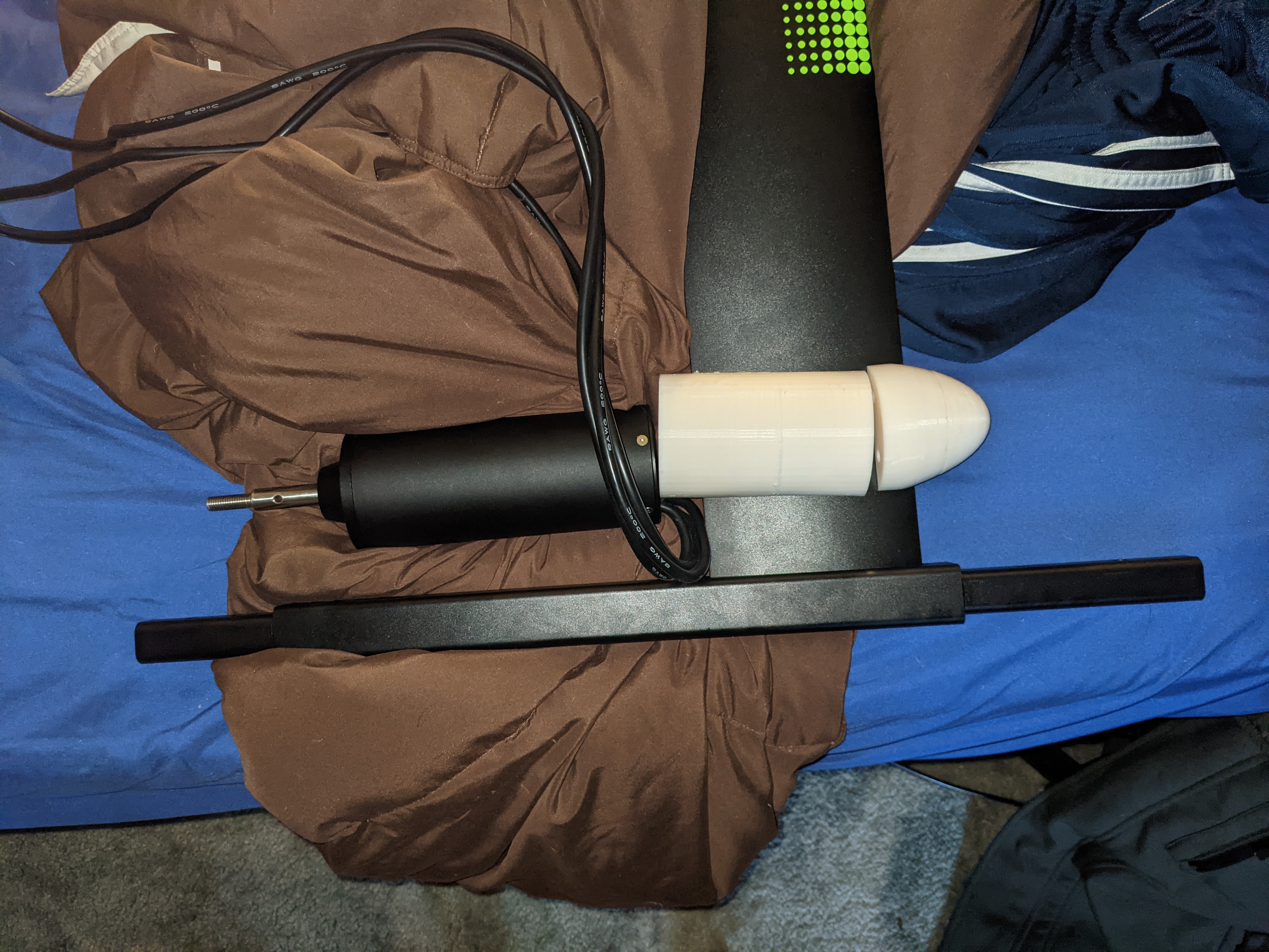
I used these threaded rods and these flat head allen socket sleeves to accomplish my M5x135 SS dreams.
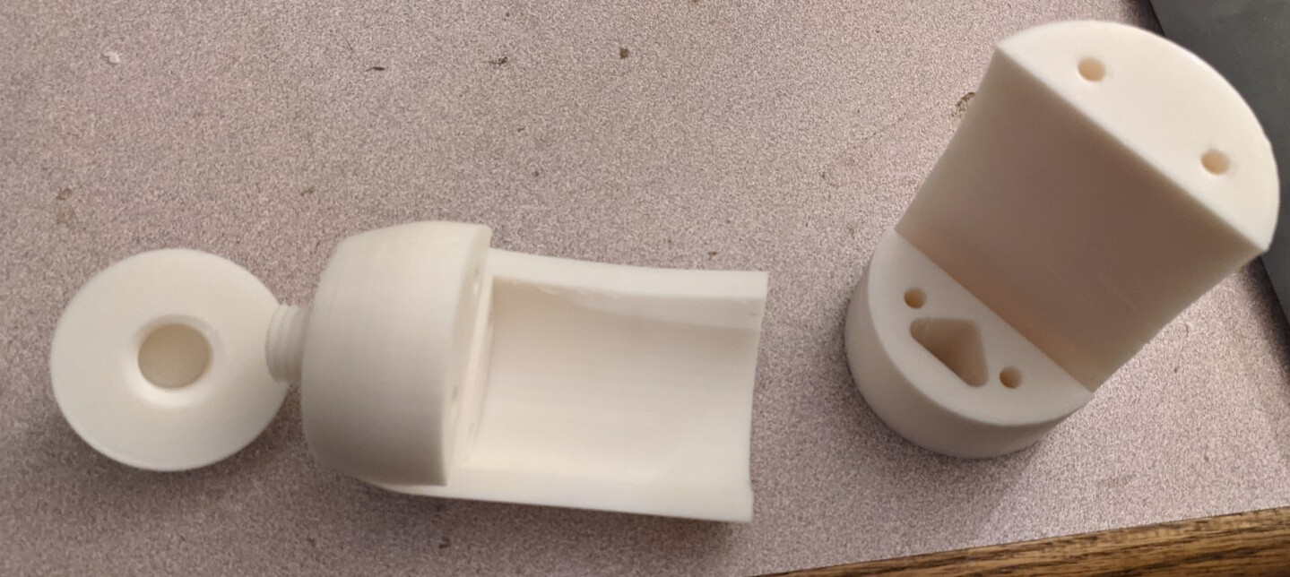
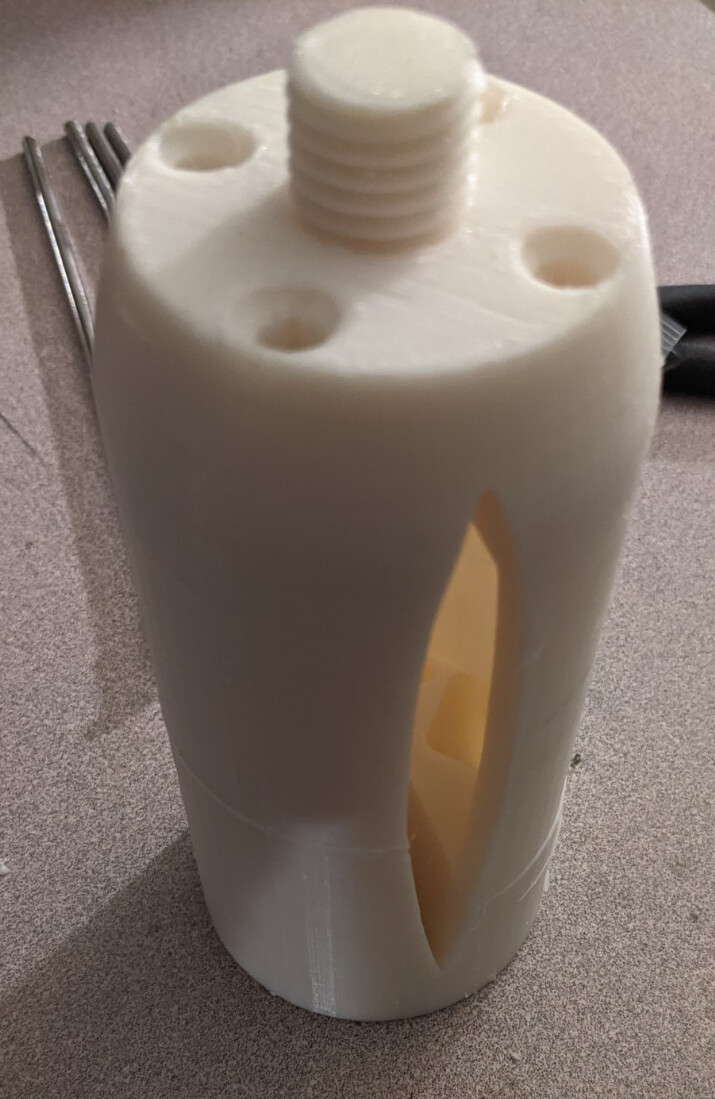
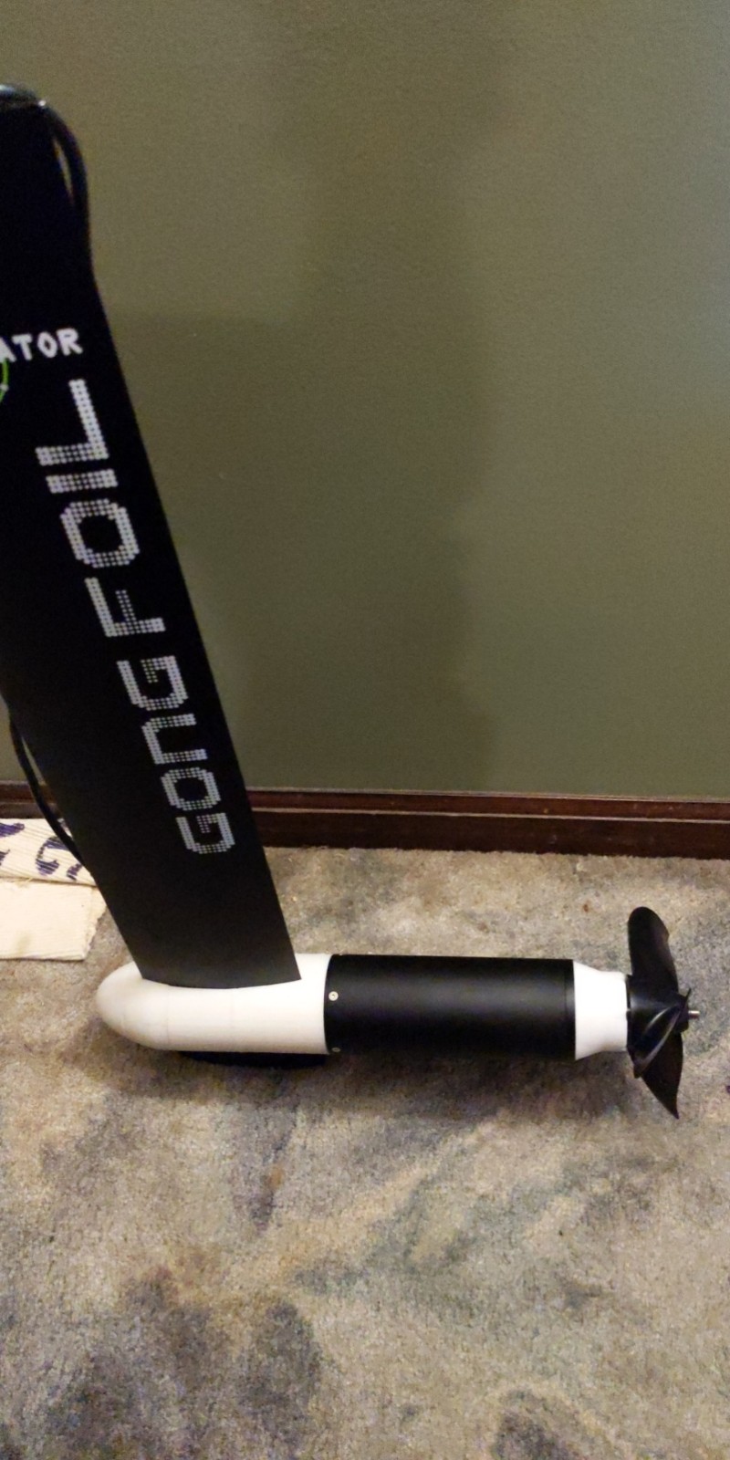
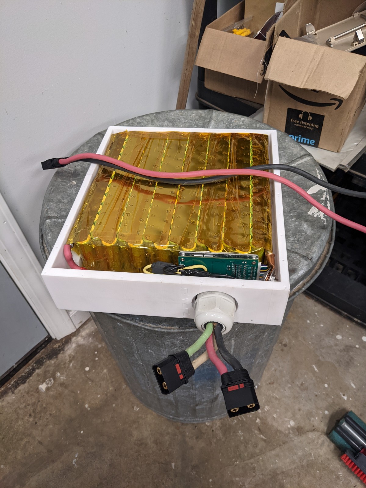
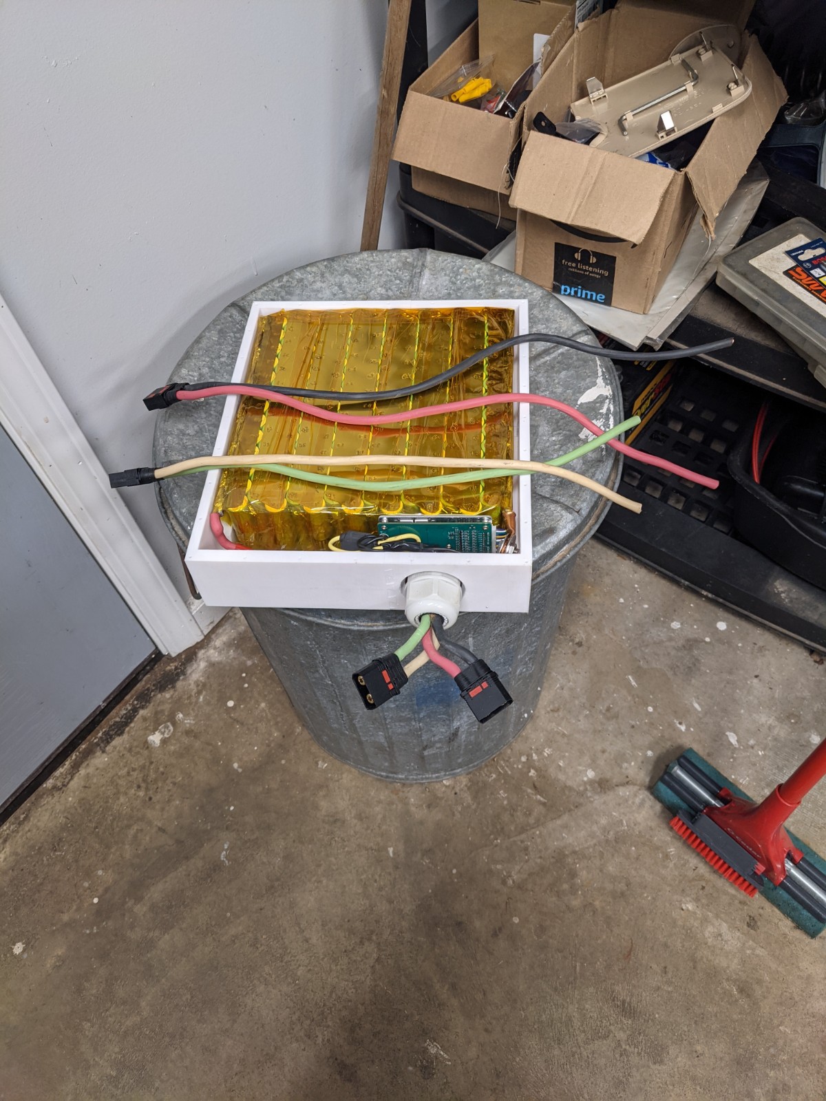
Photos of printed clamp:
Everyone is talking about the flite board and inplane thrust and its benefits. I was also thinking about how long my 65161 looks hanging off the gong mast. I mocked up a model of a fliteboard copy to work with the gong setup, I think it could work provided the 3d printed parts are strengthened. I think hollow printed and filled with epoxy and fibers would work.
I know the model is sloppy and is definitely not to scale yet… I am unsure if I want to take this path so I did not want to put in a ton of time into details. Some of the shapes could be optimized.
If you don’t put the motor in an aluminium tube, it’s probably better to attach the tail part of the fuselage below the mast, not to the motor.
Like this: New build from 3D printed molds (very low cost, but high performance !) - #47 by visor360
Why? The motor shell should be plenty strong I would think. I was just thinking since it’s already there, might as well take advantage of it’s length rather than add more material for a tail piece if I don’t have too.
And it looks like the flite board attached it’s tail at the motor fuselage.
How do you want to fix it to the motor? There are strong forces to the mast and fuselage, when you ride the efoil. I don’t think the motor case suports this. DIYS and serial production are different things. I also think the Flite is a one piece metal case, the geared motor sits inside. You would need an aluminium tube wirh an ID that exactly matches the motor OD, then weld it. Not an easy task.
You are right. To do it the way flite did, you would have to figure out a way to somehow add something to the outside of the motor tube that is not too cumbersome.
What about mounting the tail boom to the end of the motor in the existing (6) M4 holes?
If I can mount the tail boom on the end of the motor, then my tail boom is short (because the motor is long), reducing the moment forces directly on the tail boom and translating those forces into the motor and motor mount attached to the fuselage (which are strong).
I think the main reason I would be scared to use the motor as a fuselage would be the thread engagement of the (4) M5 bolts in the back of the motor. I think if the rear wing hits the ground or rocks or anything there is fair chance the rear wing could deflect the motor badly and pull the threads out in the back.
Hi, i think you should first sort out where the wires will pass through the mast and fuselage. Then figure out the length of the fuselage. And only finally deal with the rear wing issue.
I’ve been thinking of doing the same thing with a gong mast, Just need my mate to draw this up on in fusion 360 and 3D print as a negative to use as a mould to make it out of CF.