Long time lurker from Pennsylvania. By my readings, this forum has single handedly brought down the price in $ and time to build an efoil. I appreciate everyones hard work.
Anyway I finally decided to pull the trigger on the build. Trying to use it by July. We will see. Using all of the information I have gathered here is my first post towards the build:
I plan to buy a blank and pick it up locally from: https://greenlightsurfsupply.com/ and carbon fiber it. I want to use a waterproof battery box, a separate waterproof ESC box, and a deck style hatch to cover everything. Have not found the hatch or boxes I want yet.
I think most boards are 60-100 liter boards. If I want someone to try the board that weighs 200lbs (changed the front wing) what is the smallest board they could use?
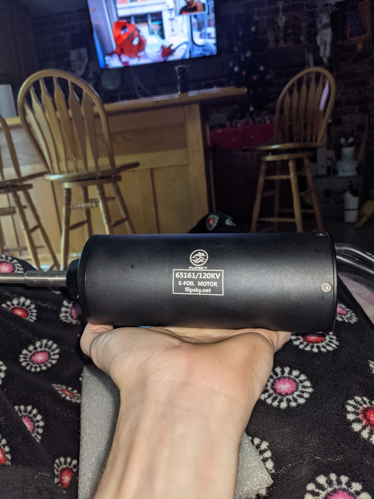
Motor will be the flipsky 120kv 65161. Still thinking about the prop. Could 3d print… might just start with the provided one.
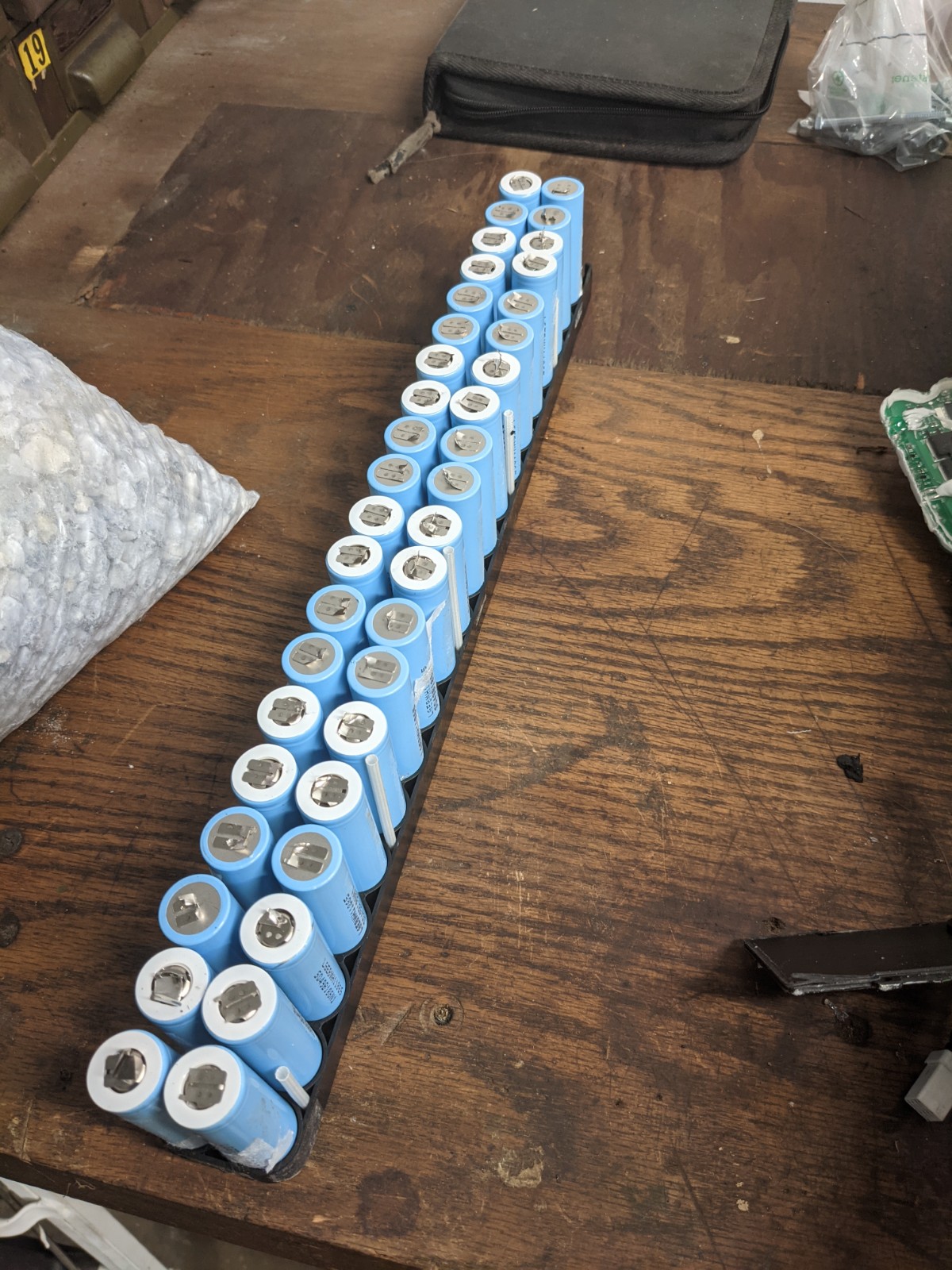
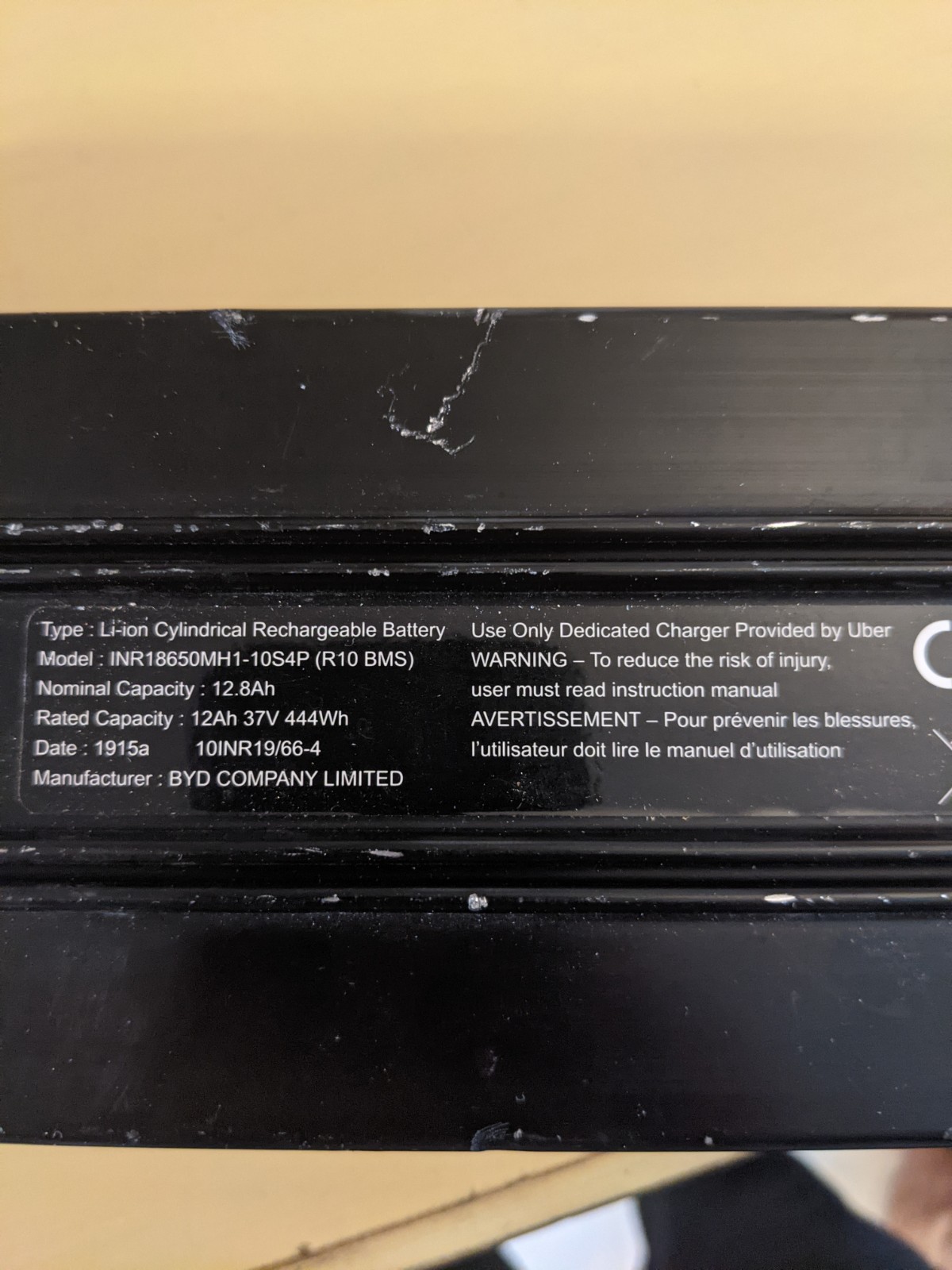
I have 18650s on order. Will build a 14S(10-14)P? battery. Still need to find a good BMS.
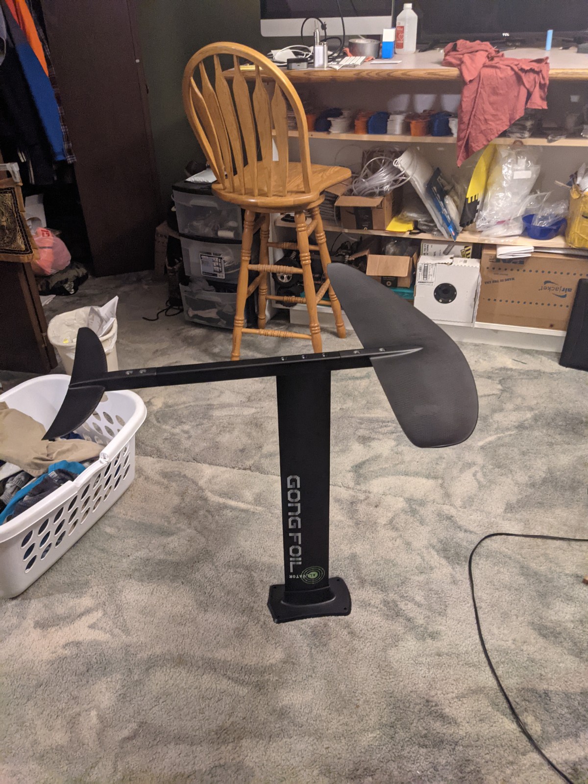
I only weigh 65KG or 145lbs to I decided to buy this foil: GONG SURF FOIL ALLVATOR CURVE ALU CARBON - MT.
Other parts include: kill switch lanyard, solenoid, maytech remote
I understand this is not the most detailed post and I missing a bunch of parts, but that is because I am still figuring out the BOM haha. Basically instead of hardcore engineering this, I am just going to buy all the big parts I know I need, and then once I know real life sizes, I can select the next components and figure it out as I go. But if I do not start a thread now, I never will.
I am looking at charging / balancing options. I could go with the bluetooth ANT 300amp that is well known on this forum but I do not want to carry more electronics on the board than I have to. I think the cheapest option would be construct to the battery with a connector for the BMS, and only attach it during charging. Would something like this work?
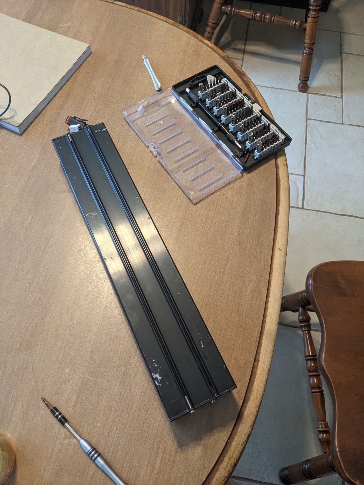
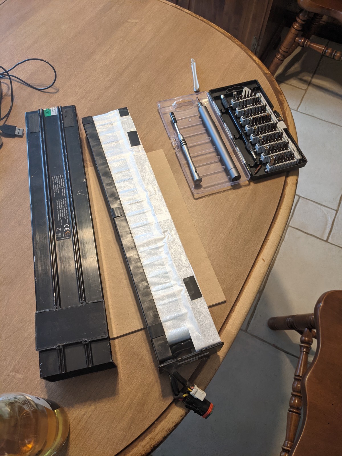
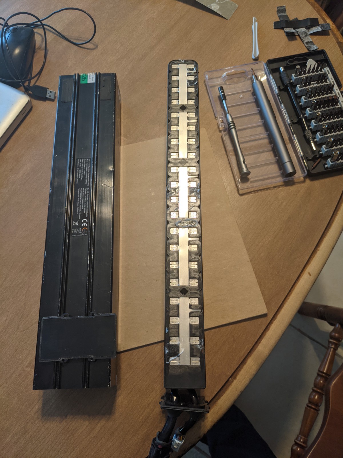
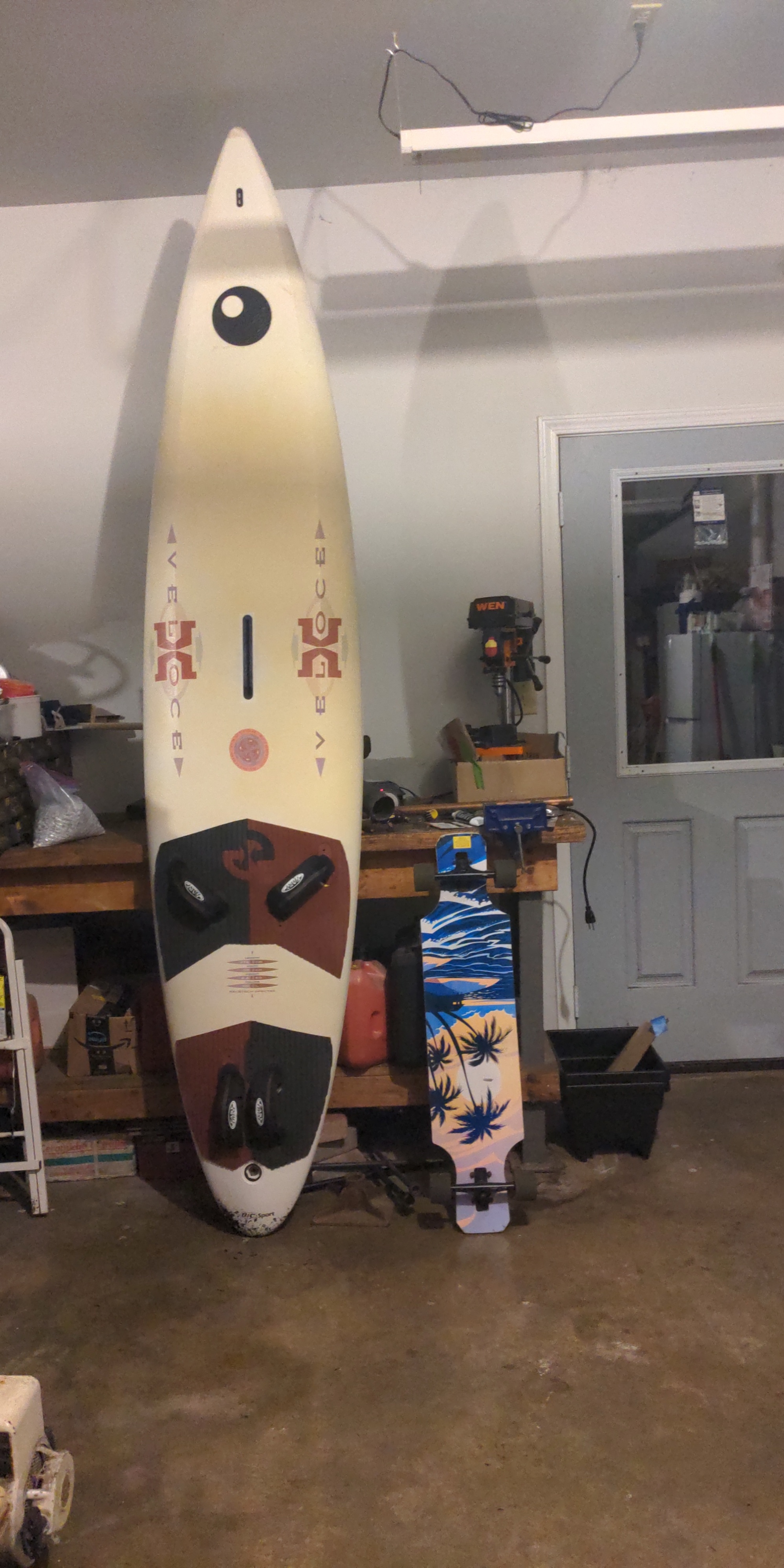
I decided I should try and modify an existing windsurfer, to hone my fiberglassing skills, before I go all out on a carbon build like I wanted. Here are the parts I have purchased thus far:
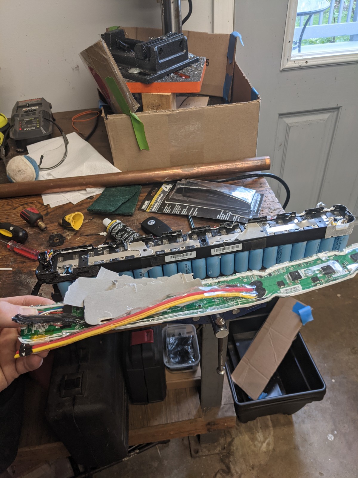
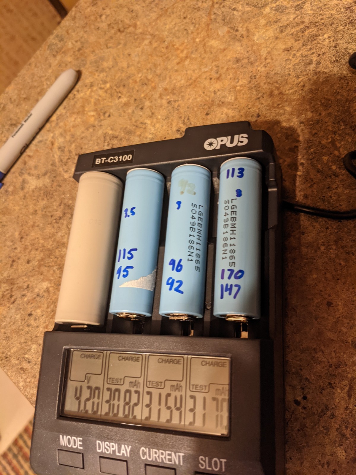
I have been using this battery charger to test the internal resistance of each cell. Cells have been testing between 70-130 milliohms. Probably about 5% of cells tested are between 131-210 milliohms. Those cells will not be used.
I write the resistance of each cell after testing. I did a full capacity test of a couple cells to see if internal resistance correlates to capacity. It seems too. (ignore gray battery)
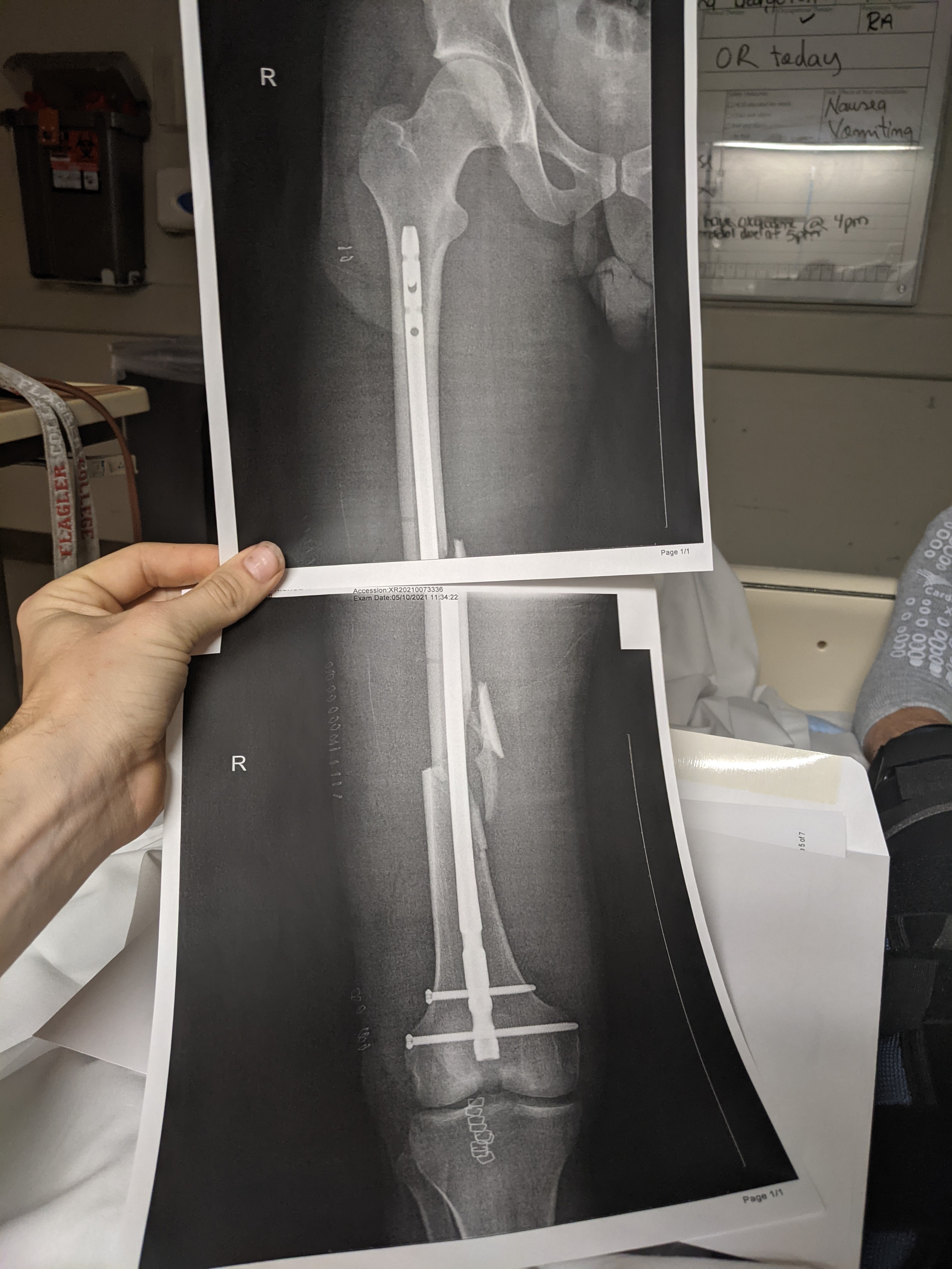
Now for the bad news, earlier this week I broke my femur in a bad motorcross accident. So I have lots of time to post! But I cannot walk, so building is out of the question for a couple weeks.
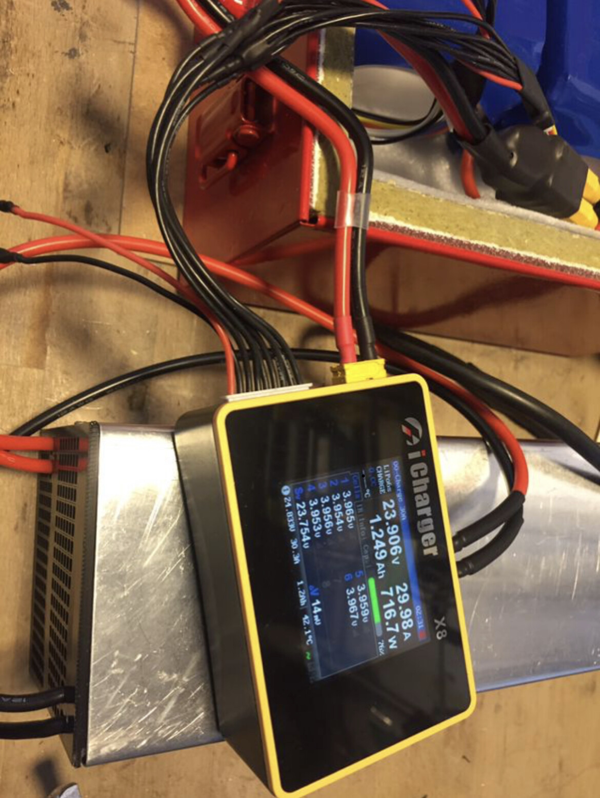
You could also split the battery into two 6 or 7S packs, this way you can use standard RC chargers with balancing cable. Icharger X8 for example. Bofore connecting 2 or more PSU’s in series, you need to separate the - (gnd) from the case on the second psu (the one that connects - to plus of the other one). - is usually connected to earth so you would short one psu.
Chaepest way to build a psu is from used 12V server psu’s, you can modifie them (separate - (gnd) from case) and connect them in series. For a 6 or 7S battery, 2 in series are ok, you can increase the voltage a little bit and get 25V.
Whith such a modded psu you can charge two batteries with 30A each (with 2 Icharger X6|8 chargers) or you can charge two batteries in parallel with one charger@15A each (30A total).
I have seen the x8 chargers used before on here. People seem to really like them. They seem pricey, but also maybe I do no understand all of the benefits.
I have put more thought into the charger, and I think my cheapest option would be to use a BMS and float the grounds in the power supply as you suggested (Thank you for the link!). Now I know there are mixed opinions on BMS’s. But I am trained in electronics safety, and plan to construct the battery pack safely with the BMS integrated. I will only use the BMS for charging.
I think the biggest consideration that should be made when integrating a BMS to a battery pack is how the balancing wires are routed and keeping the wires from rubbing through. I think I will also fuse my wires, which I saw somewhere on this forum as well.
Question:
Lets say I want to hook server PSUs in series to charge my 14s Battery. At 4.2V per cell, thats 58.8 Volts (14x4.2). It was my understanding that in order to charge, I need a higher voltage coming out the charger to create the voltage potential needed. So I would need 5 PSUs wired in series? (12x5=60Volts)
Yes , to charge yours 14s through your bms you will need 58,8v , 60v might be a little to high for your bms ( check this ) , so 5 psu in serie which on some you can tune the voltage ( and you need to cut the ground on 4 off them )
In this case you probably better get an adjustable 60V psu, 5 server psu’s are too heavy and a bit of an overkill. One advantage of an RC charger like ichargerX is its built in dc/dc converter, it can adapt the output voltage within a certain range (to 8S fo X8).
I agree 5 server PSUs would be overkill. I do not think a single circuit in my house would even handle that. Ill look for an adjustable voltage psu.
So a standard circuit in my house runs off a 15amp breaker and 110volts or 1650watts. So without splitting the battery pack, at 60V, the most amps I can push is about (1650/60)= 27 amp-hrs into the pack during charging before the breaker blows. The BMS is rated for a max charging rate of 40 amps.
It takes a single 2.5 amp-hr 18650 battery roughly 3.5hrs to charge on my good 18650 charger at 1amp. It charges up to 4.12 volts then backs off the amps slowly until 4.20 volts (as it should).
So if I am using a 14S12P pack with 168 cells total and 2.5amp-hr capacity per cell, that means my pack should be at its core 2.5amp-hr*168cells = 420amp-hrs at 4.2V OR 30amp-hrs at 58.8 Volts (both equal 1764watt-hrs).
This means, that if trying to charge the 58.8V 14s12p pack as fast as my house will allow me on a single circuit, it would take roughly 2-3hrs to charge by my calculations.
I do not see a ton of data on this forum about average charging times of packs. So real world data is greatly appreciated.
Assuming I am correct, than I would buy 2 of these power supplies or similar which put out 24-30volts at 22.2 amps for 160$ total, connect them in series while floating the ground off one, and be good to go. I think this is cheapest option.
Need both a rd6018 and 60-70 1000w power. About 180 it looks like
I have a rd6012 right now and plan on using that with a custom BMS I’m working on.
On my 12s setup I currently use, i split it into two 6s packs to charge on a ichargre 406duo that could charge up to 1400W Or about 28a if you have 24v+ input. Was using 2 server supplies with a float but one died, so right now charging both at ~14amp. (With 12v 62a supply)
So took me a little over 1hr before and about 2-2.5hr now.
I really liked your recommendation! Thank you very much. Best price point I have seen for my needs. And as a bonus, I do not currently own a regulated DC power supply and I am sure I will find many uses for it in the future. Just ordered the RD6018 and accompanying power supply.
So I have noticed around here Kweld seems to be standard for building battery packs. It produces nice welds, there is no arguing there. I want one, however, in the spirit of “lets save 50-100$” am willing to try and build a welder without the Kweld, from parts I have laying around, for free.
I appreciate any and all criticism, the approach is based off this youtube video.
From what I can tell, the major things you need are: some copper rods for electrodes, a car battery, a larger solenoid (200ish amp), some heavy copper wire, and a momentary button switch. I have all of the items on hand that are shown in the video.
The solenoid in the youtube video cannot be rated for more than 200amps at 12V. I understand about 1000amps is needed. I think the “welder” in the video is shorting the battery and relying on inrush currents to create the weld.
I have not seen this approach very often on here, and I will lose the adjustability the Kweld provides, but if it works, then it works, I have not problem with that. Has anyone taken this approach before or see any flaws in the plan? With all materials on hand I figure it is worth a shot.
Hello sorry to says that but when you’re starting a batterie build, soldering is not a light thing buy a good spot welder because you can loose more when fire is due about bad solder…and for charging the lithium i prefere a slow charge at 5amp/h it make 5 hour to charge 1of my 2 6s10p 18650 samsung 30 q for longer life and it just need a 6s rc quality charger with a simple 20 amp dc alim no need 160€ …for me the 18650 build and all electric components is the best quality invest you need to do for safety ,peformance and longevity…fire ruins the hobby🤙
Nothing is worth the shot is Efoil world , just safety and quality work to get away of trouble , get a decent spot welder , make the battery and sell it if you went to save some money , don’t forget we are talking about more than 600 spot weld for a this king of battery for me that was sweating and letting my fingers cool down
So I have been thinking about this for 2 weeks but cannot decide on the best design. The goal is a detachable mast design. So initially I was thinking female plugs on the bottom of the board that the mast plugs into. But I’m not sure if that’s the best. Looking for advice. I want it to be easy to remove mast for transport.
I’m planning to try putting an aluminum plate on the bottom of my board where I attach the foil, and then cut a slot for the 3 motor cables to pass through. Inside the board I’m using 2 IP67 boxes with grommets and in-line connectors between the battery & motor boxes and between the motor and the ESC box. The connectors are MUCH cheaper that way, should still be very water resistant if water gets in the board, and should still keep water out of the board.
That’s a good idea however I’m not sure how that makes the mast detachable. Do you plan on making the slot big enough in the plate so the IP67 connectors can fit through? Or can the outer shell of the connector somehow be removed so you can pass the motor wired through the slot?
My bad, that wasn’t clear. I was planning on making the slot large enough to fit the connector through. Then it should be fairly easy to take out the 4 bolts on the mast and pull the cables & connectors out. They’re less than 1" O.D. so it shouldn’t be hard.
Hi, we both have a common goal. I can’t show a picture yet though, maybe early July, I might be able to make it. However, I have the quick release system very carefully thought out, but all I can tell you now is that the connection to the mast will be made by two long screws (possibly titanium).
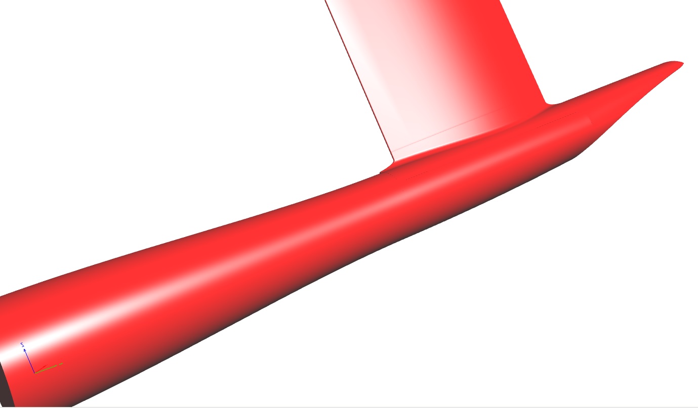
Unfortunately, our goals diverge in other respects. I have started an e-foil project based on the Fliteboard hull design(https://cdn.motor1.com/images/mgl/1M9bK/s1/fliteboard.jpg). The Fliteboard e-foil is considered the best in the world. Placing the motor in the plane of the wing is ideal from a hydrodynamic point of view and brings a number of other design advantages. This is my fuselage design
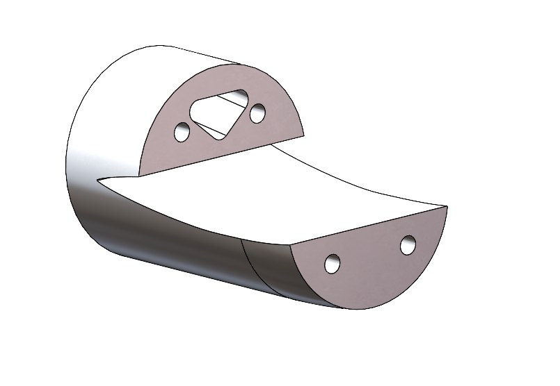
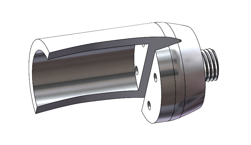
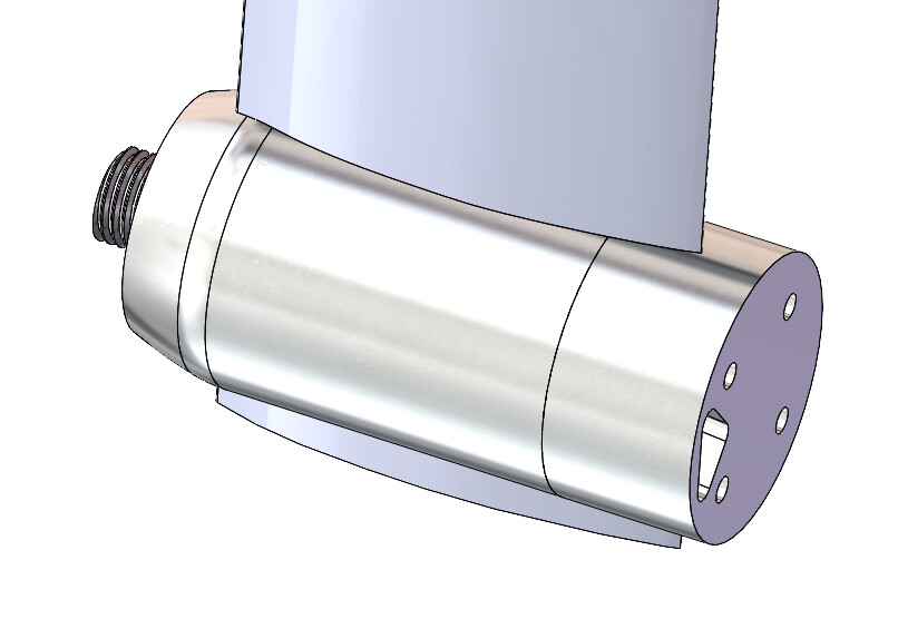
Did some work on the mast clamp design. Inspired by @nice2cu and @manu clamp designs. Have not loaded them into the printer yet. Also nose cone not finalized. Designed for gong mast V1. The reason for large cavity is because I want to run wires up both channels inside the mast. Not just one side. This way I can access both channels inside the mast.
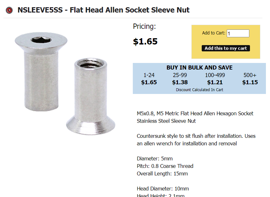
Question to my USA friends, where are you getting your super long (135mm+) M5 bolts from? Are threaded rods being used?
I am going to use threaded rods and these cool adapters I found from belmetric. My friend is a stainless steel welder, I envision screwing this on the whole way and welding it to the threaded rod.


 for me that was sweating and letting my fingers cool down
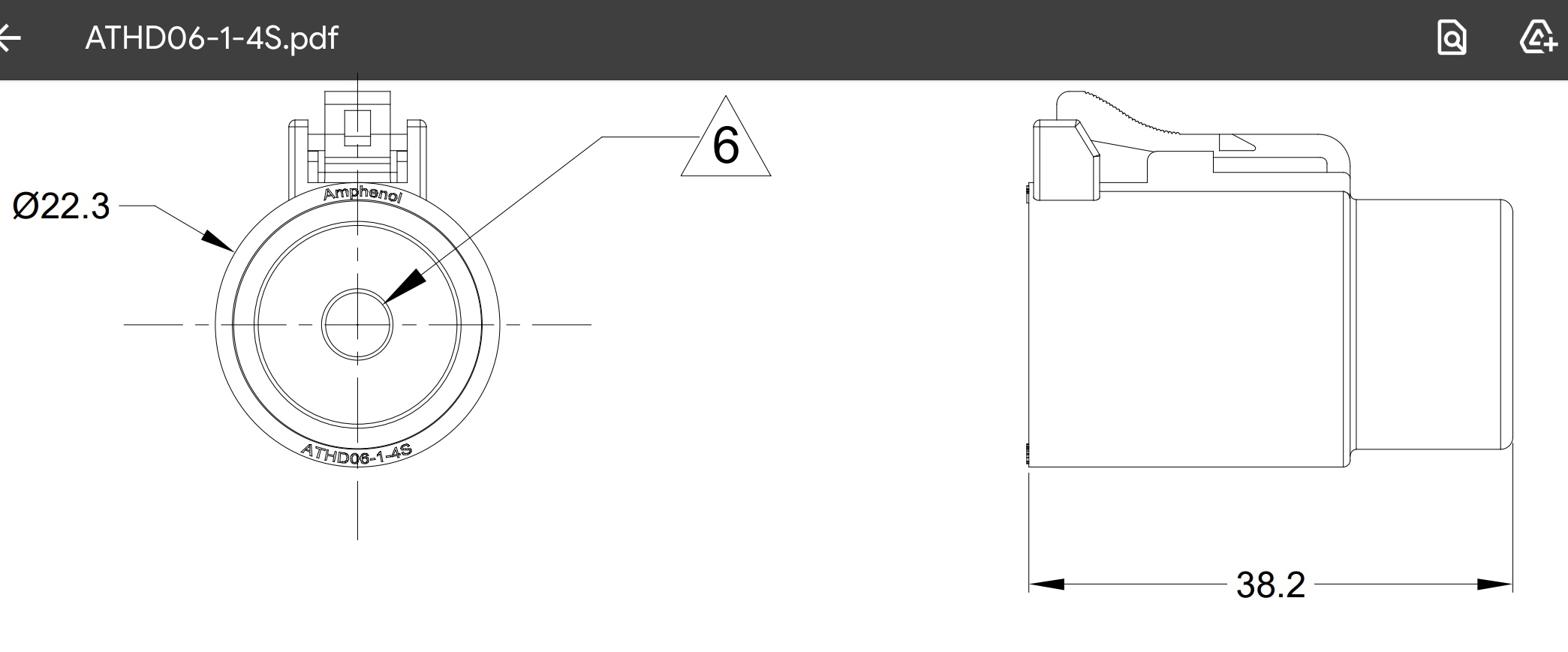