So even if corrosion happens, it can be cleaned, I guess, (though the coating can be damaged). But you are confident that contacts remain functioning no matter what…it is great.
These xt90 are spark protected , right? I see some are black inside. Did it happen to you that the spark protection of the connector stopped working?
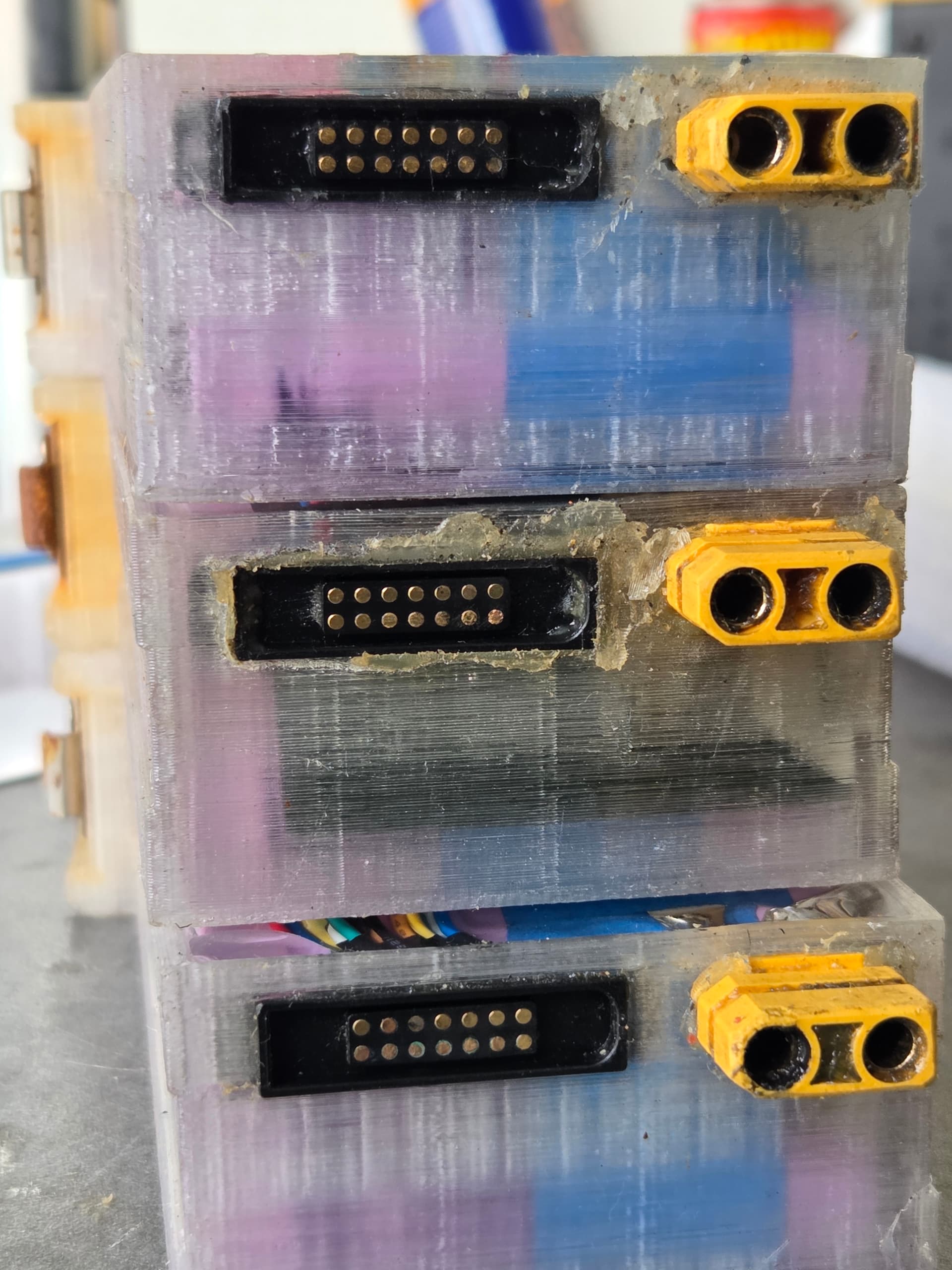
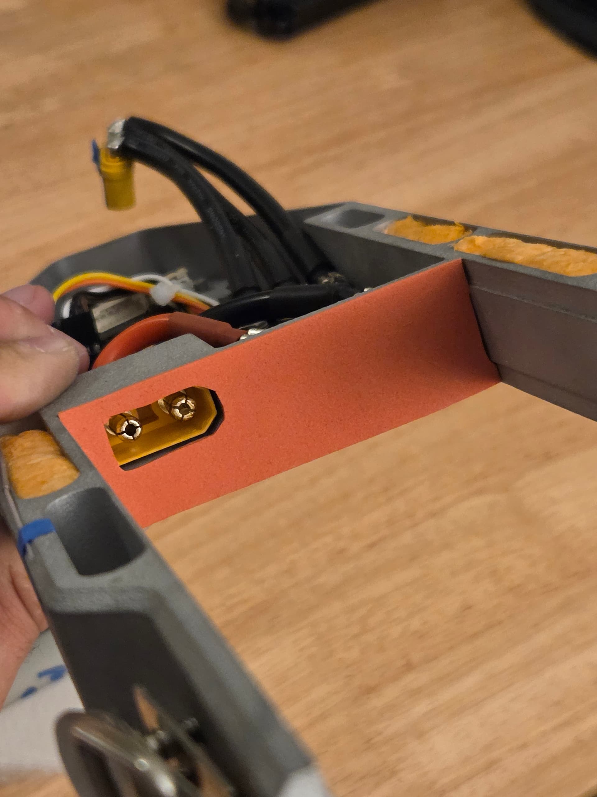
Started with waterproof XT90, but since I improved the seal I will use XT90S instead. The sparking is pretty intense on plug-in, and controller side with male pins is not replaceable after potting…
For the pogo, yes they can be cleaned, I had a few where the coating got damaged from salt water droplets. With 35E cells, I mostly just check the balance from time to time with a multimeter, I don’t need to use the balancer so much if at all.
That sparking is not good, I have built a battery with a built-in connector and connector got destroyed. Since then I will use battery built-in connector only if adding mosfet ramp up.
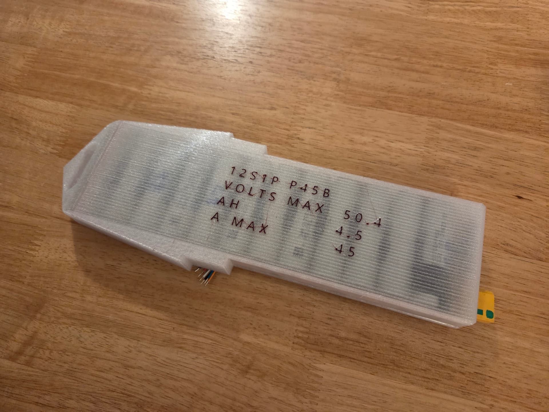
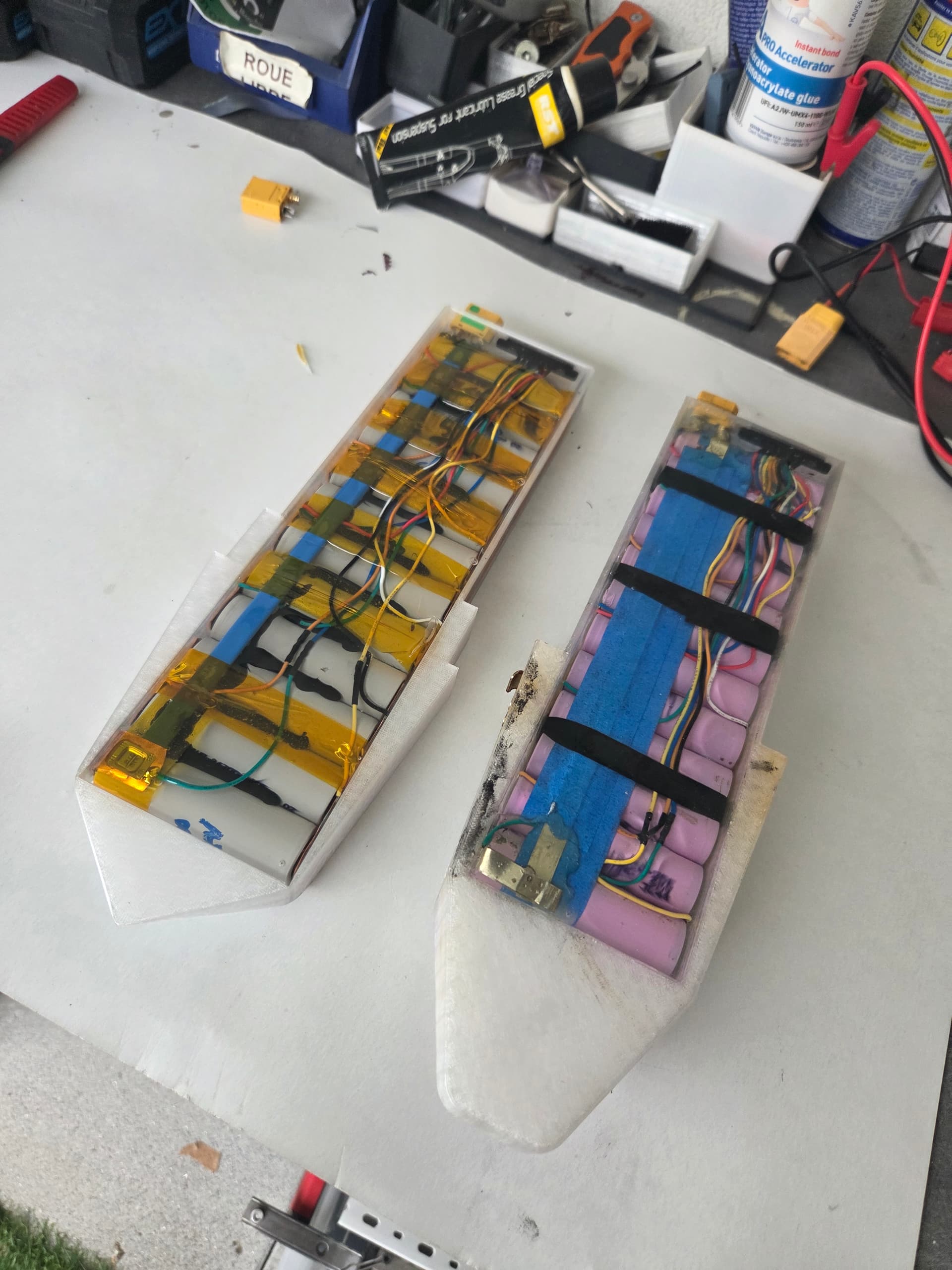
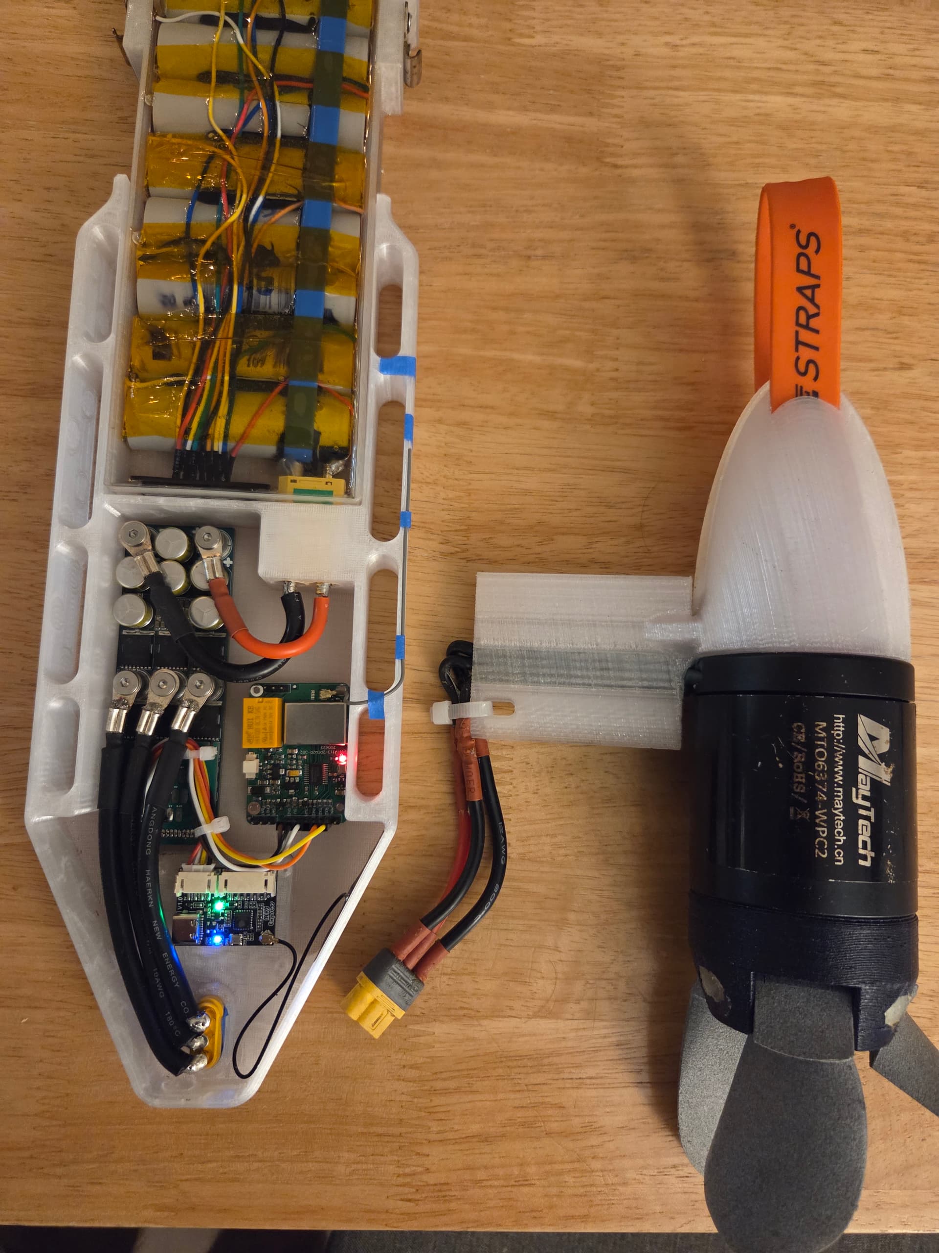
I use that bak 45d cell in my batteries, it performs very well as expected. Battery stays cooler and run longer than p42
BTW it would be great if we could use eve 4695e 30ah cell. It is lighter, cheaper and more performant. But for 670wh capacity we can chain only 6s. Maybe use higher kv motors.
'EVE 4695E 3.7V 30Ah power cylindrical lithium ion batteries
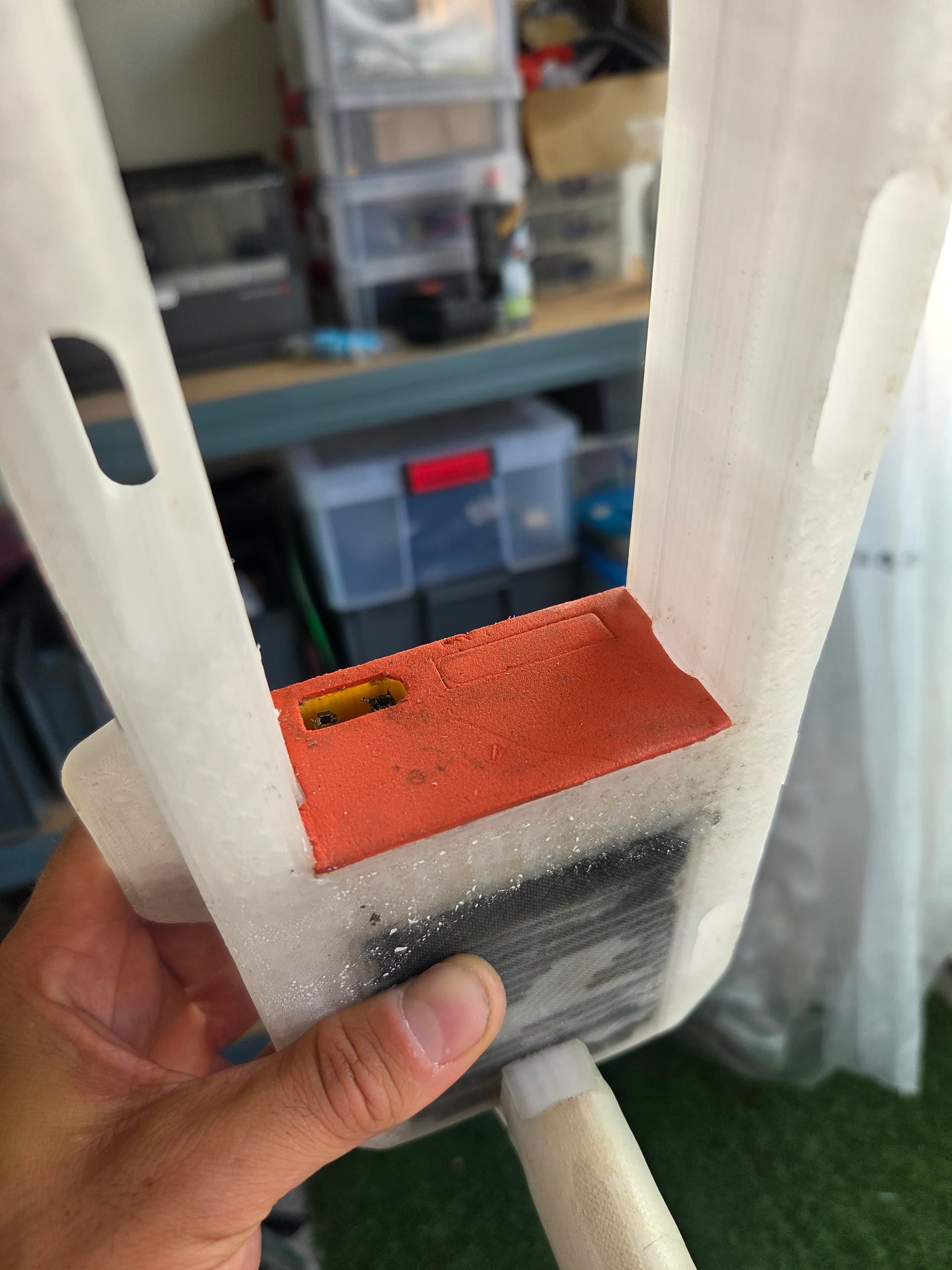
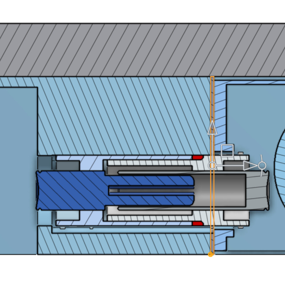
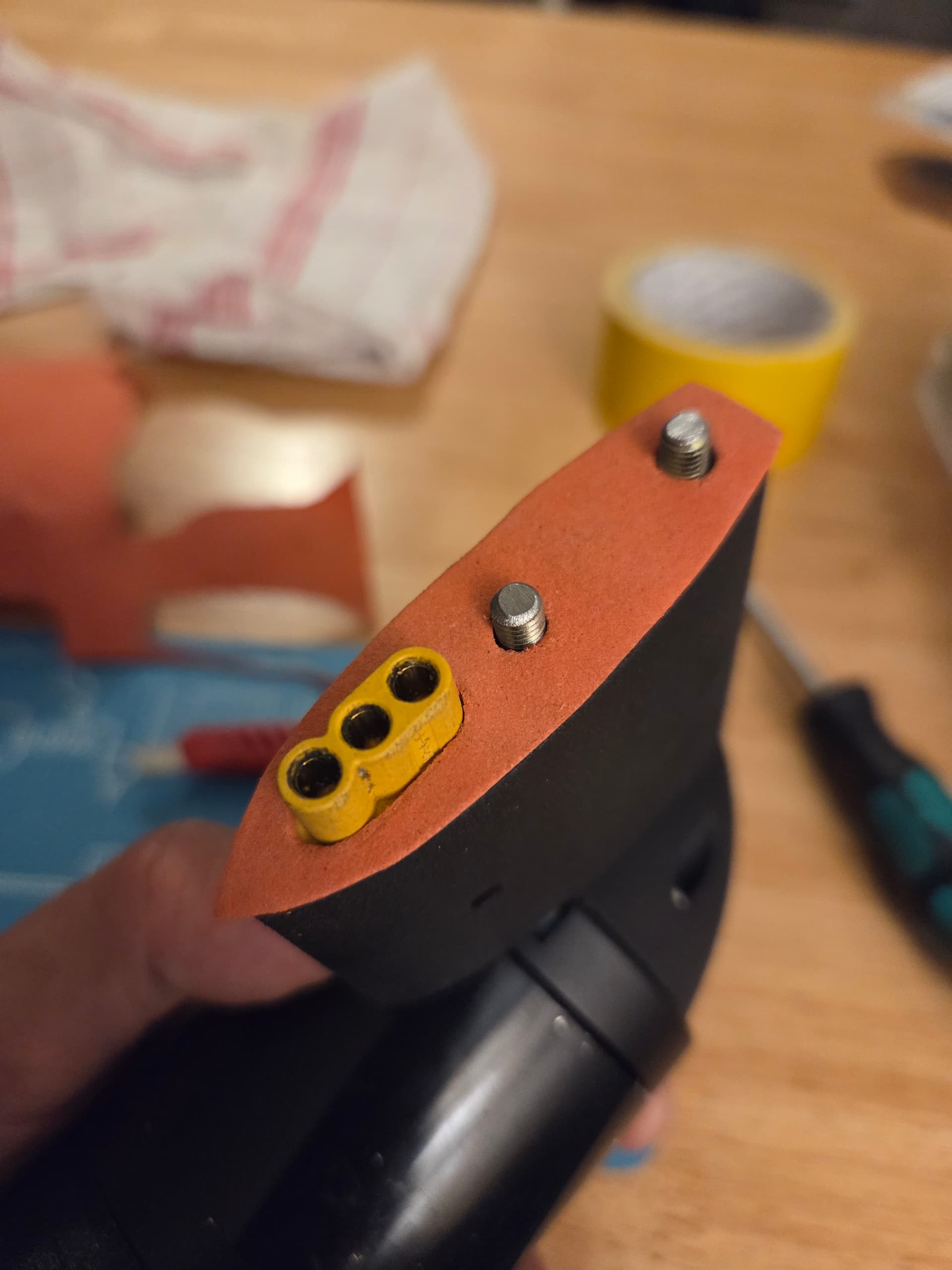
When the battery press into the controller, the foam seals both flat surface, and prevents water into the XT90 and into the pogo.
With the new flat seal concept, I can run normal XT90S and seal the pogo better.
Just a head up, XT90S plugs are thought, so during potting, make sure they are fully soldered, or that you added some sealing inside to prevent epoxy weeping from the connector.
Yes this is right, have to be carefull during storage and battery swap in water. This is why I still silicon grease the contacts.
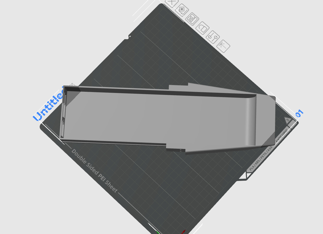
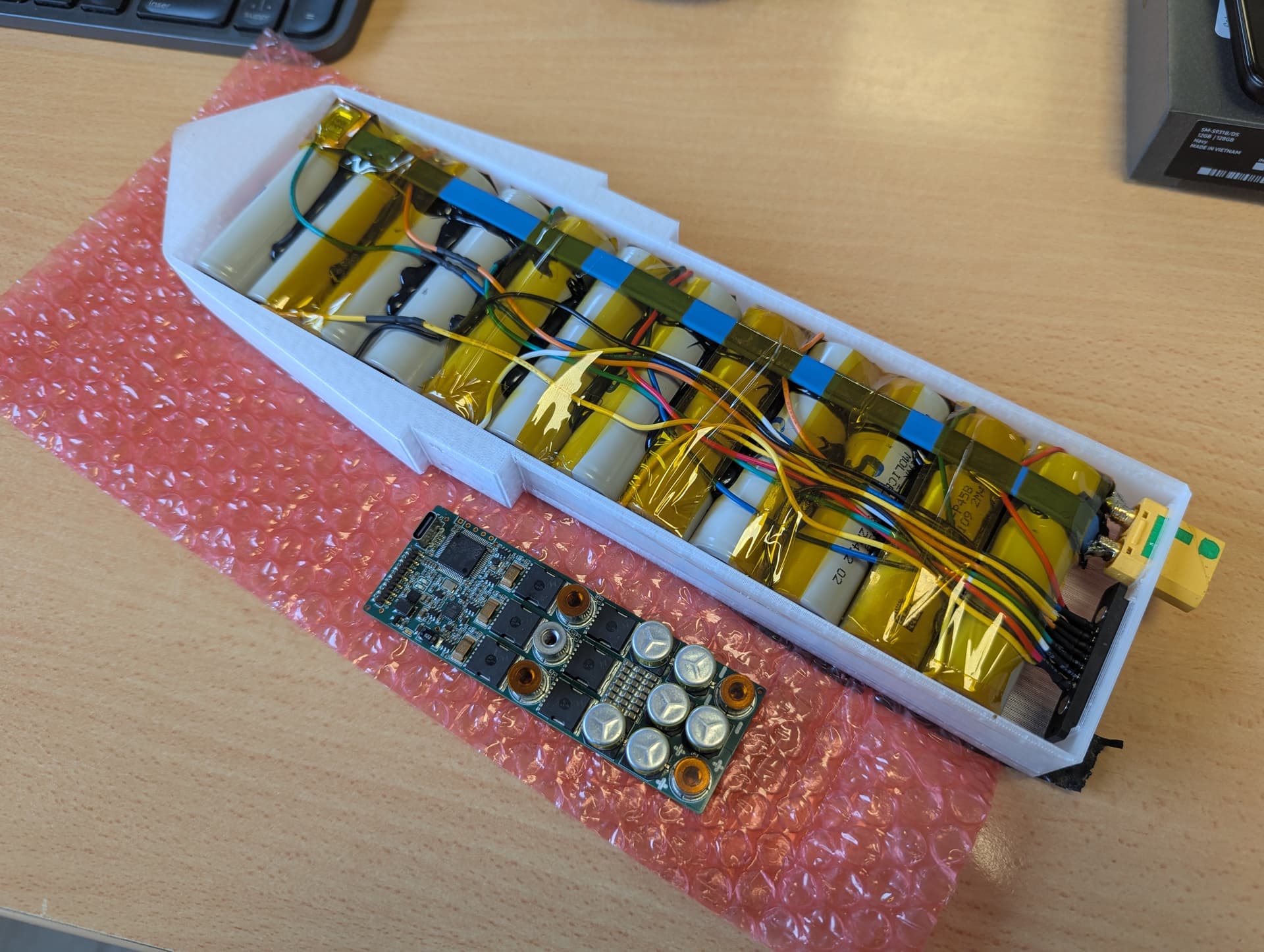
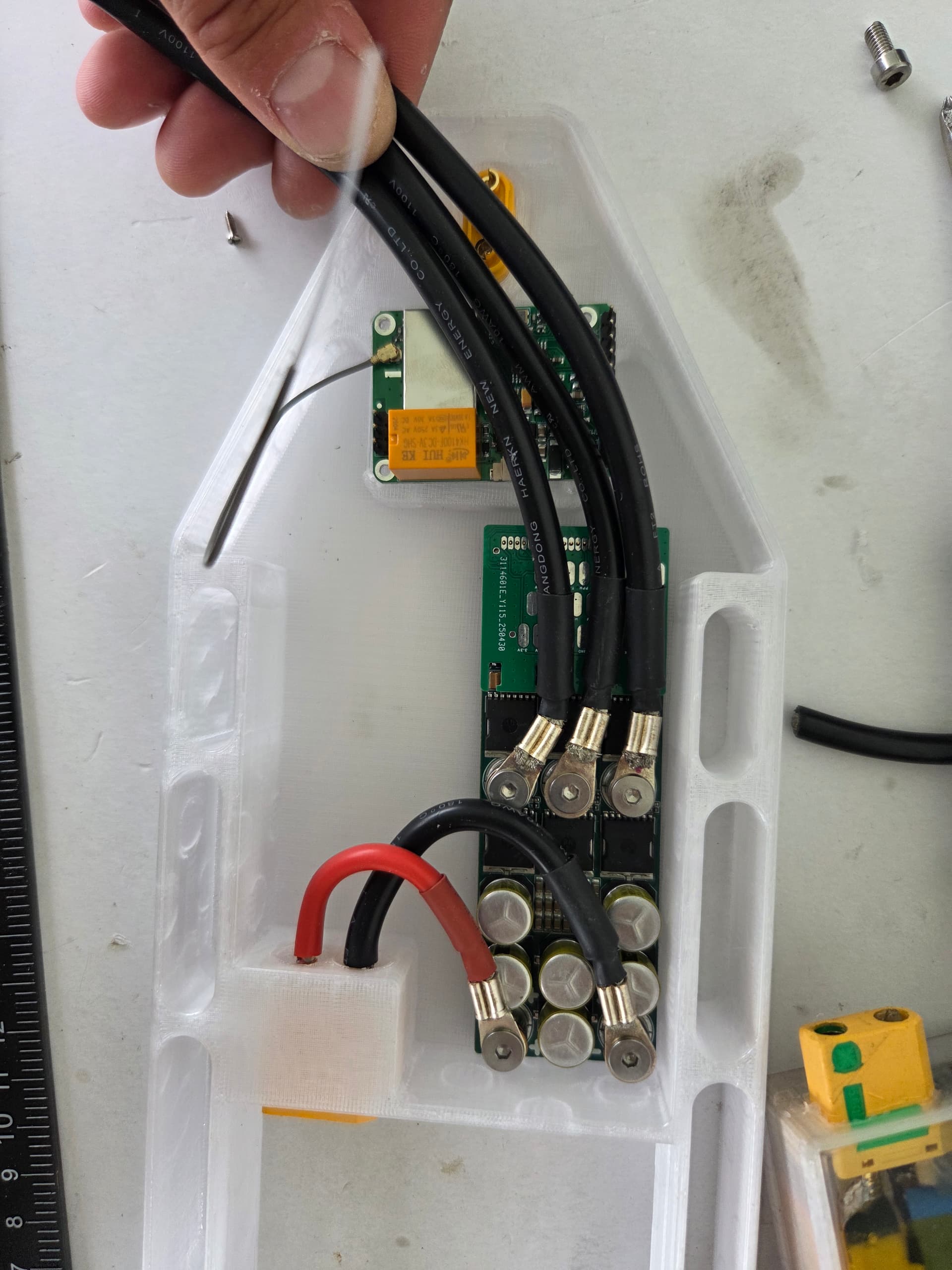
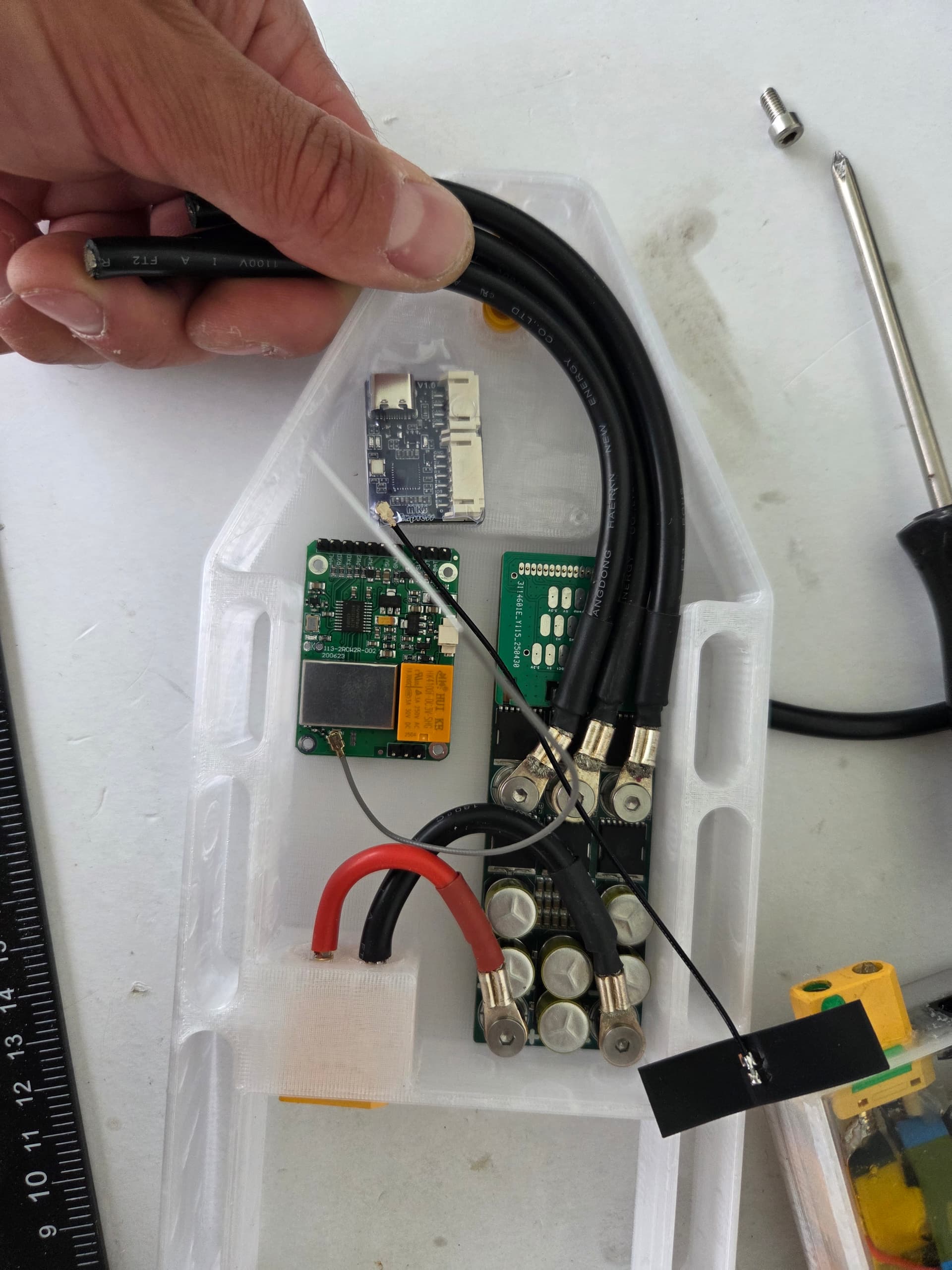
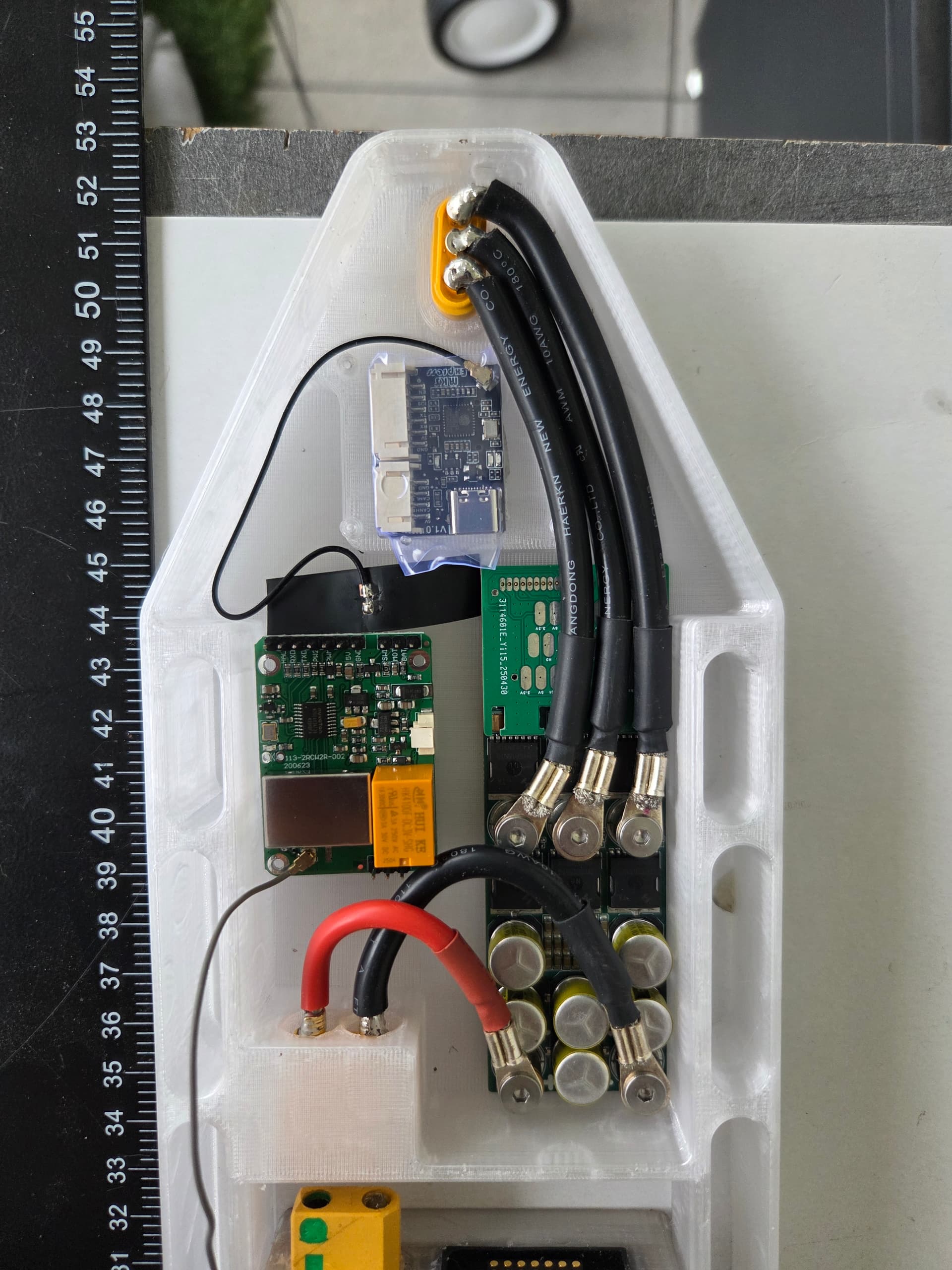
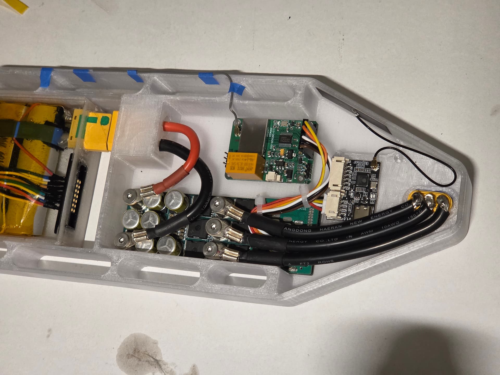
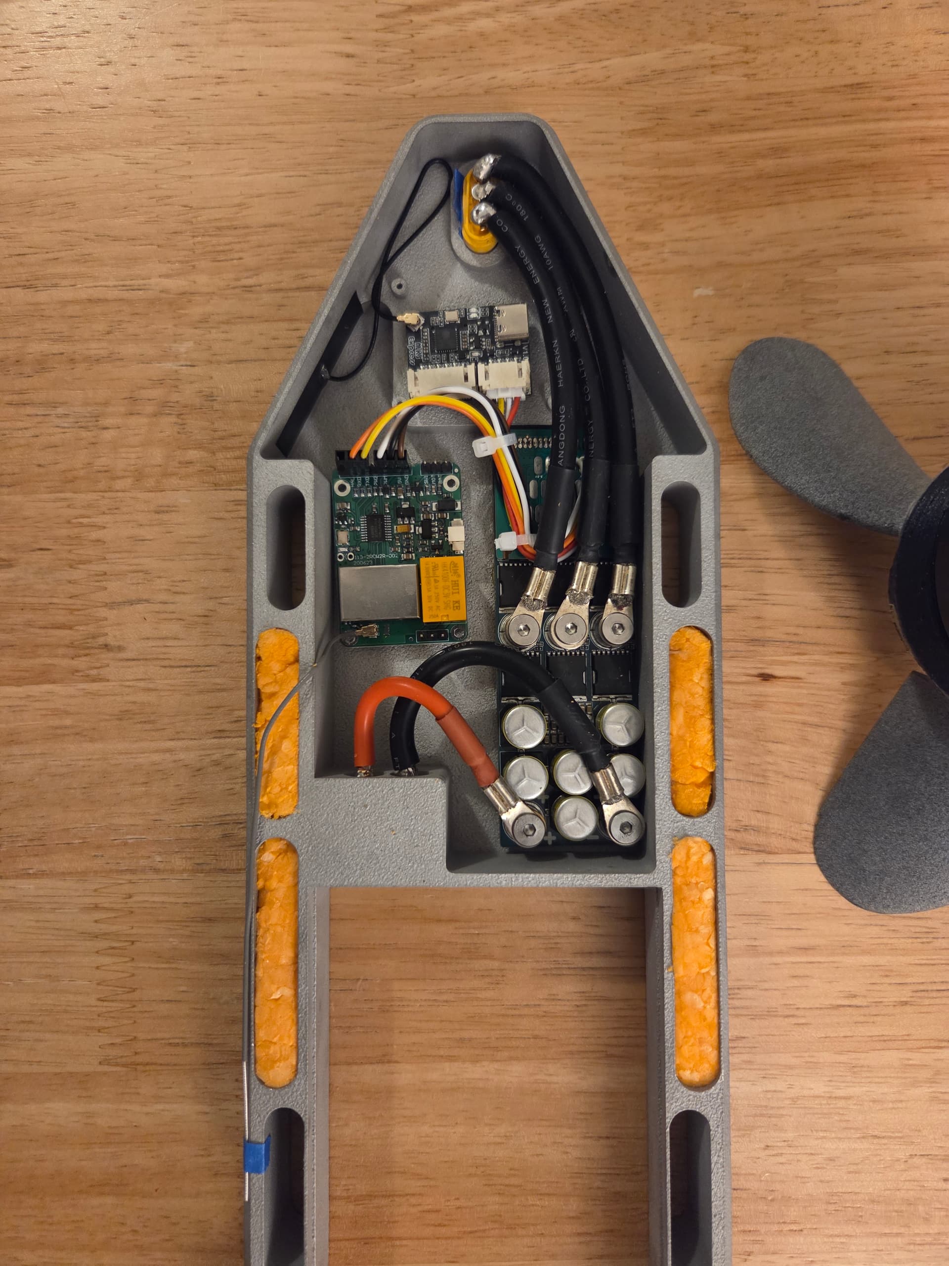
Printed a dummy controller part to check wiring.
The initial plan with rx mounting is not ideal, and I reworked the layout a little.
Next I have to prepare signal wiring and make it clean, then I can test it all before installation in the alu part. I will aslo design a part to hold the electronics and wires all together and reduce potting volume and weight where possible.
Regarding the rx antenna, I did not yet fully think about a clever solution. I should have added a tray such as in v2/v3, it is a working and simple solution.
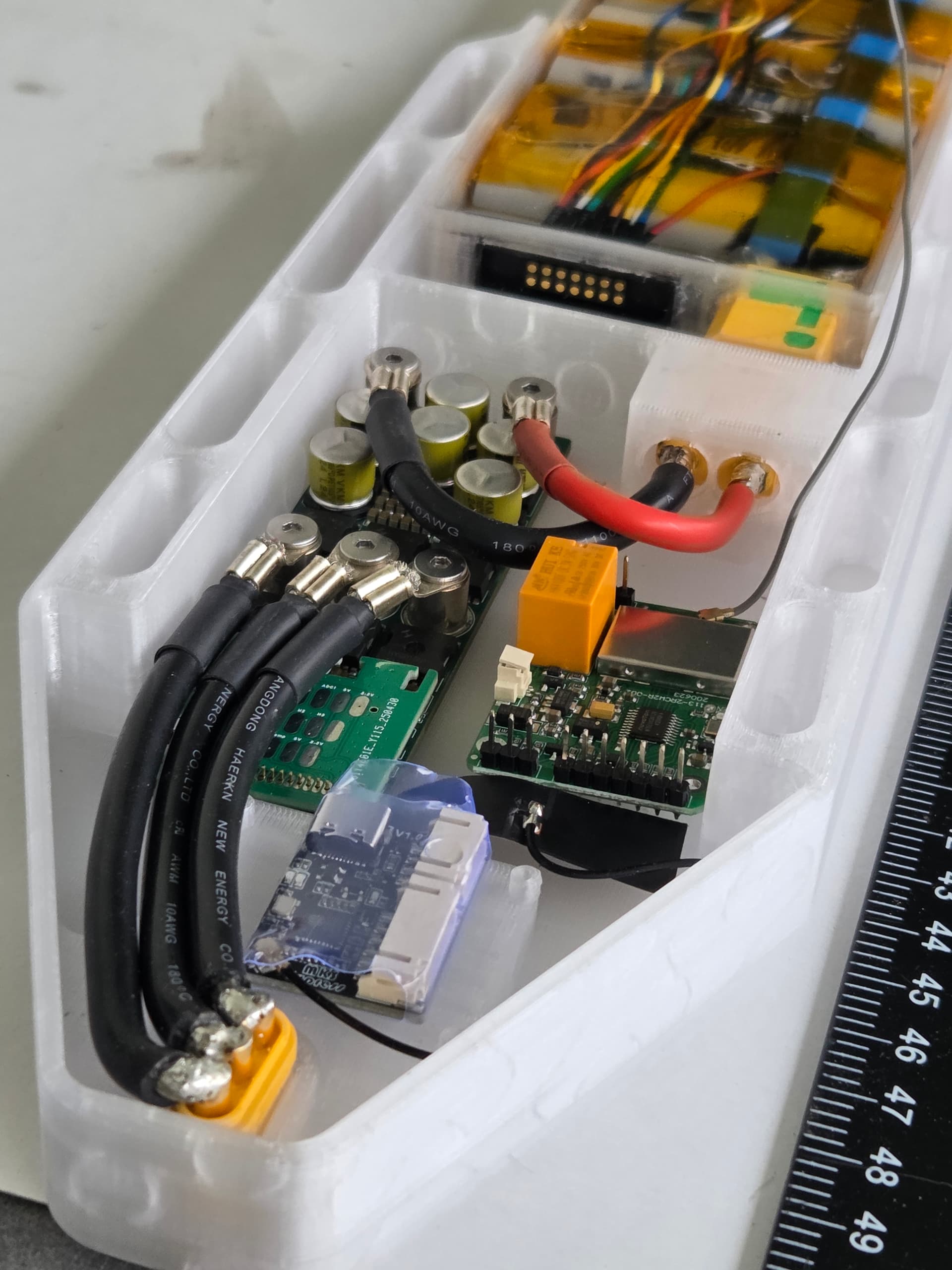
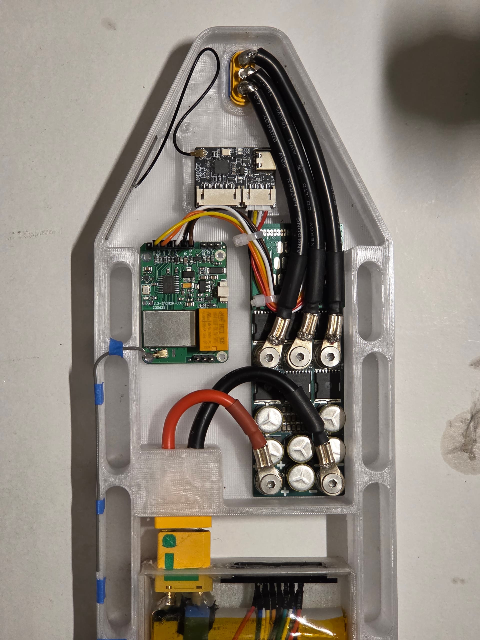
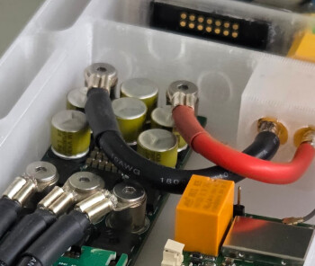
I would recommend to add some insulation between the top of the capacitors and the wires, usually the capacitor housing is connected to either the + or - of the cap.
Not visible in the picture, but there are extra spacers below the +/- lugs to raise them above the caps. Will add barley paper in critical areas, like between the phase wires of MR60 (very tight with 8AWG, 12AWG would be OK for assist use) and below the RX to insulate the pins from alu.
Below the controller, I will add a layer of kapton tape, then thermal glue.
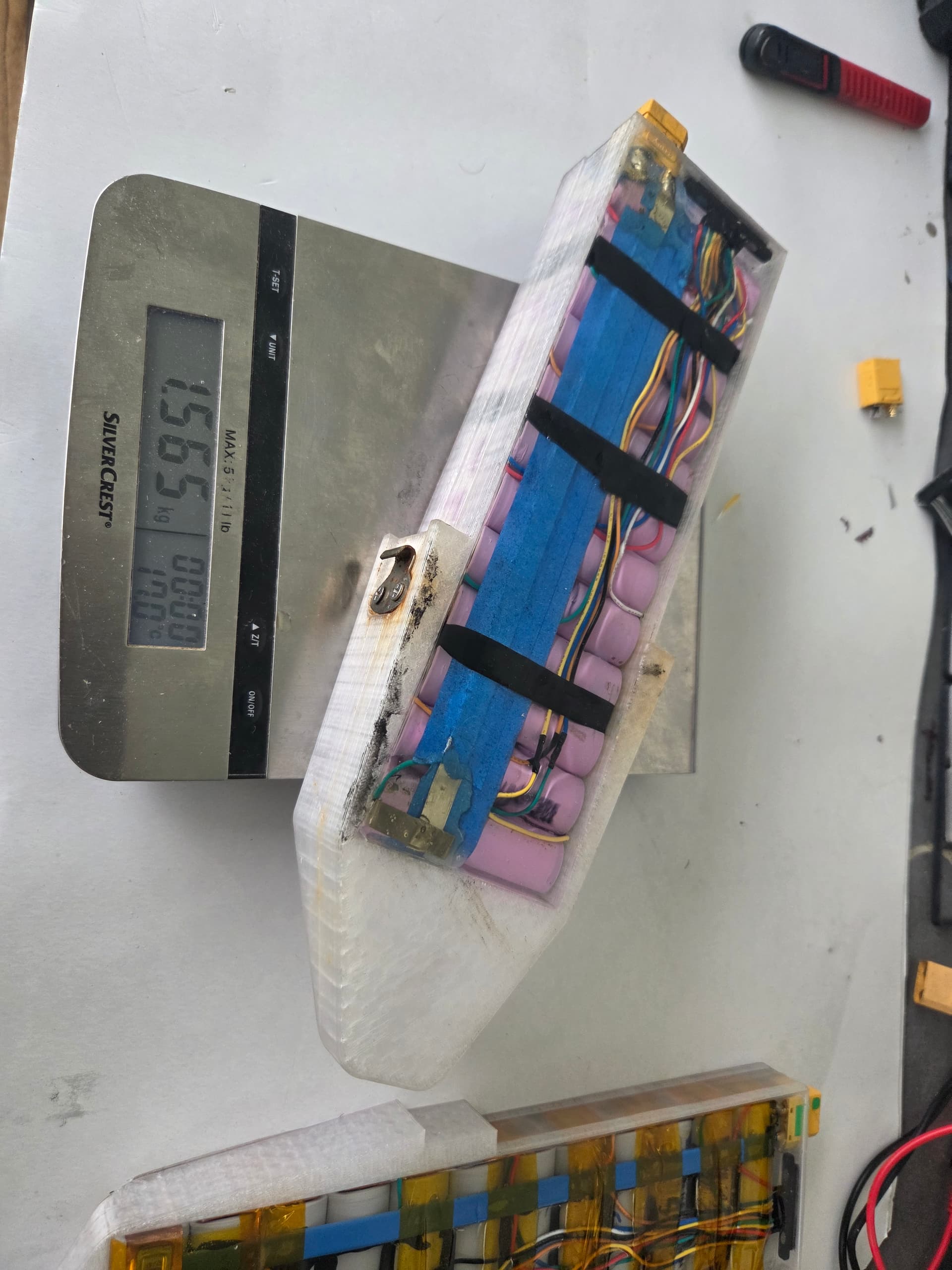
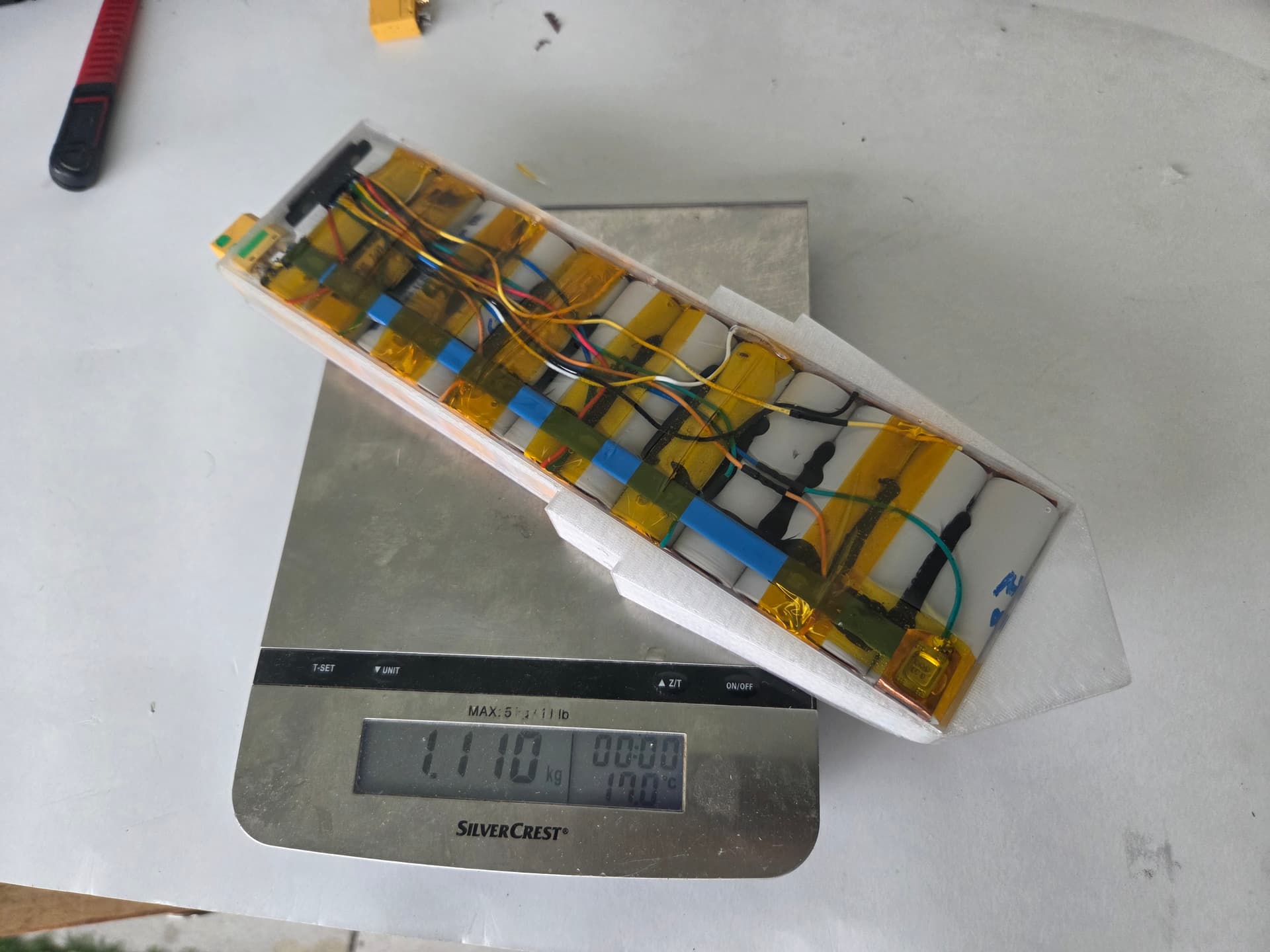
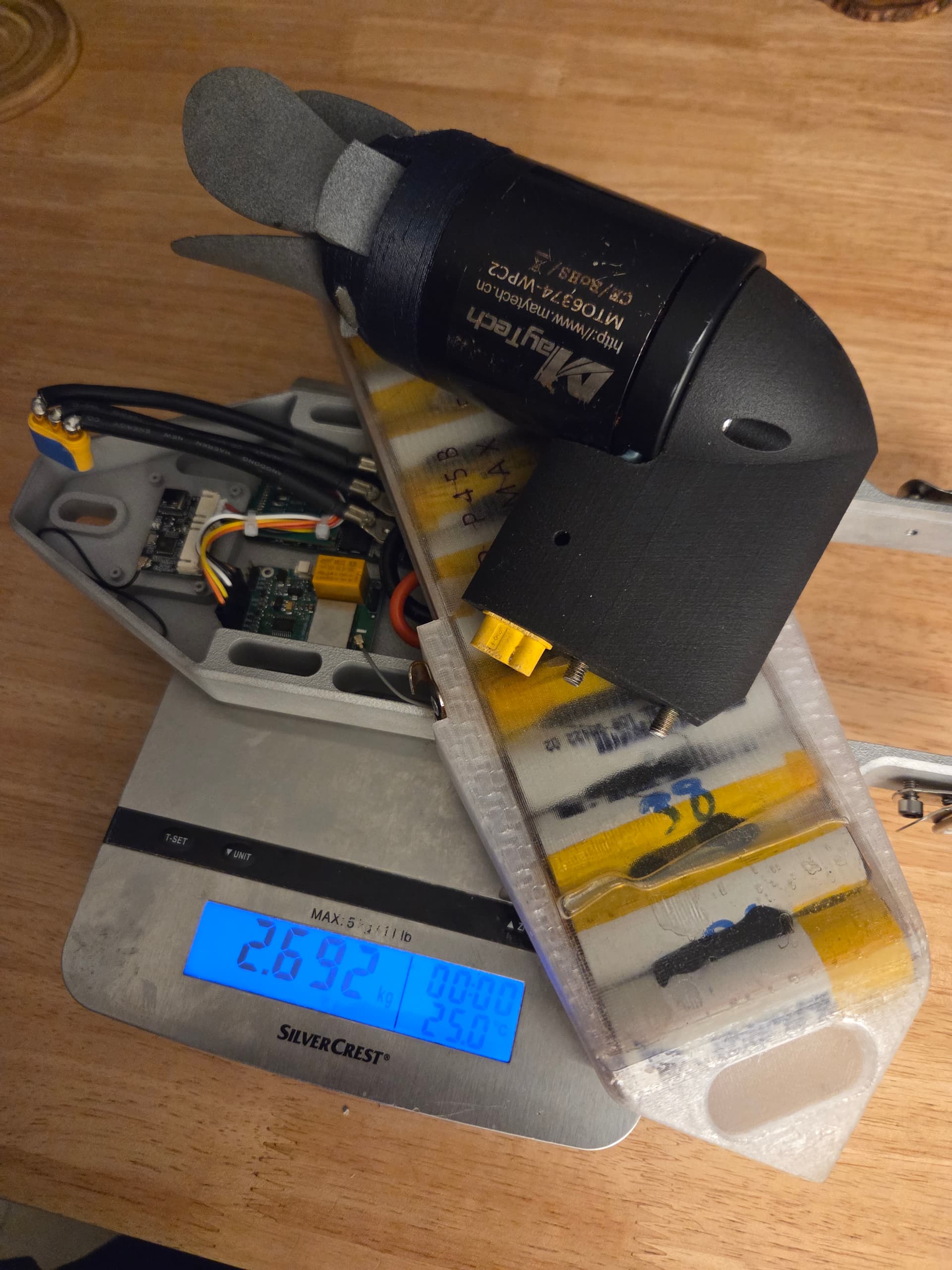
Should be 2800-2900 gr finished
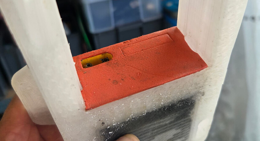
Some photos of the seals concept for phase and battery. The hole on the side of the pod is for potting for the mr60 from the back.