I’m running a Flycolor HV3 160A ESC with a Maytech V3 Remote and a 12S2P Molicell P42A battery pack.
The remote shows the battery level dropping fast when I accelerate — sometimes it even says 0% while riding, but goes back to around 30% when I stop ( for example, I picked any numbers just to make the point)
ChatGPT says the correct battery state should be read without load (voltage bounce-back after riding), while Maytech support told me it’s under load that matters.
What do you guys think — which one is more accurate for these remotes? What should I be looking at to get a good ride time without driving my batteries too low. Thanks!!
is it set to 12S and to 3.7V nominal? Percentage will drop under acceleration yes, since you will have voltage drop. Going from 30 to 0 could be possible if you draw heavily from your 2P config, high amps make cells sag like crazy. Considering you have a 160A esc and only a 2P i think that explains the whole thing.
Yes the remote setting is 12S and 3.7 volt. Luckily soon ill get another 2 packs, to make 12s 4p.
It was more a general question, if i should pay attention to the batterymeter when resting or when drawing power.
The 30 to 0 was more an example to state the difference between battery level resting and under load.
resting is more accurate, but voltage isnt best at determining leftover capacity. Best to check Wh consumed (vesc tool app / yours truly). Flipsky VX5 also shows Wh conusmption nowadays.
Thank you for your answer!
So only because underload the batterymeter goes to 0% doesnt mean the battery is empty!
Unfortunately i only have a esc and newly bought maytech… so thats not an option for me.
@Joka
Back in the day when my FD Assist plus was working, and from the other FD users, the Maytech remote is different to the FD battery checker display. I can’t remember but I think it was much higher, which is different to you, but that was at 8s. My Flipsky remote at 14s is useless for battery indicator.
Battery sag is a big thing under use. I’m using original FD Assist Plus batteries which are li-ion in series with lipo batteries, and the FD batteries really drag the voltage down.
I have an FD battery and the checker at the front of the board and can read it all the time, and under power it is about 10% below immediate recovery when stopping.
So all you can do is my routine of checking voltage or percentage when returning home, and the battery has recovered and base that on what percentage you are prepared to go down to when foiling.
With my setup, 4% under load on the battery checker gives me 25% when recovered, I also need to adjust my ESC battery cutoff to 3.43 v per cell. The FD battery BMS doesn’t kick in at this voltage either, even though the FD battery would be lower as the other battery holds charge better, so I can allow for the sag in the ESC.
Other battery BMS could start there, but the FD being li-ion it is allowed for.
Because of the low parallel count you are pushing the cells way past their max rating which means that the battery sag will be huge.
You should be limiting the current to an absolute max of 70A which actually should be enough anyway.
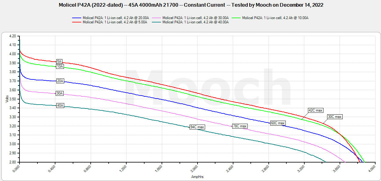
Here’s an example of how much the batteries sag under load:
Look at where each curve starts at 0 to see the sag:
5A starts at 4.05V whereas 40A starts at 3.6V (which is nominal voltage).
I’m not sure what base voltage the Maytech remote uses to calculate its battery % though.
Just do not think it is representing the actual voltage sag I feel in use.
Here you see about 0.75v drop in 10 seconds of 40A. I have my VESC limit at 3.15V per cell.
So if I ever were below 3.9V without load, I would drop below the limit and the VESC would power down. That is just not happening.
Or are those cells just so bad?
The actual sag once I am at 50% SoC or something is far less.
The other site did the test at various SoC.
I.e. start at 3.6v and apply 40A load.
Are you seeing the sag on your remote or logs? I think there are different settings on the remote for calculating voltage depending on what its set to.
In the newest version of BREmote you can calibrate. Basically just add/subtract a fixed value from whatever the VESC gives back. And additionally the new BREmote firmware can also compensate voltage drop in the cells if you tell it which one you have. This feature also works without VESC, so with analog voltage of course