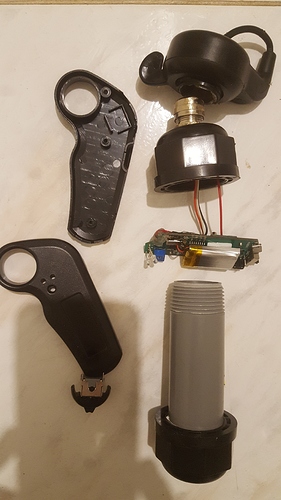
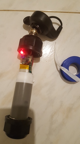
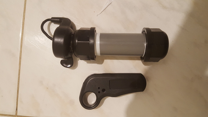
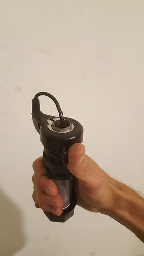
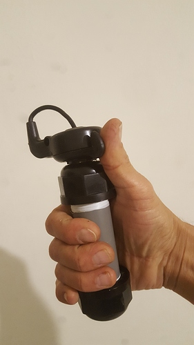
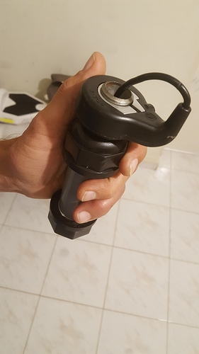
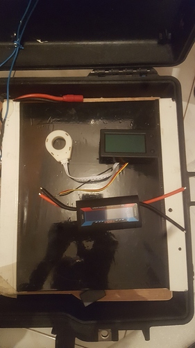
waterproof case the most simple thing there is
If I had parts of PVC and glue then it would have been easier
at the moment, it opens for the purpose of igniting and charging,
when a wireless charging receiver arrives, I will also connect a magnetic switch to turn on and off
suitable for right and left hand
I also thought about doing this, but didn’t think the thumb throttle would work with the other control board. Did you make any changes to get it to work?
just cut and salt 3 wires , that is all
That’s awesome! I expected some trickery somewhere but now I’ll order the parts ASAP! Thanks
Hi, Can you pleas share an electrical Diagram? What are the components ans the way there connected
there is a list of parts below
HI, Sorry but i am not able to see the list. Can you send a print screen?
i do not have a diagram that can not do anything but cut three wires and connect the thumb throttle
connect reed switch to a power switch
connect the wireless charging receiver to the charging socket on the remote control
Hi,
Sorry for being annoying with this but my knowledge in electrical subjects is very low. From your last comment i cannot understand how to assemble the electrical circuit.
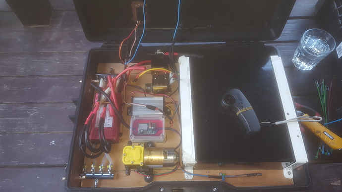
You have posted a picture with all the electrical competes above.
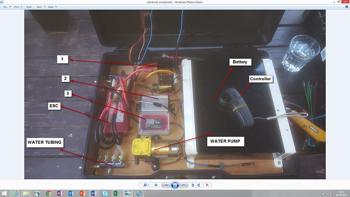
Could you please identify with arrows all the components in this picture ? What components are you cooling ? You are using water right? Why are you not cooling the battery?Best Regards,
João Rebelo
feel free and ask as much as you like for that I shared the building
at first I thought you were asking about the wireless remote
i also do not understand much about electricity, just know how to connect what is needed.
after reading almost every build in the forum
i figured out how to improve my system
as of today my electric box looks different
have you bought the parts already?
basically, I just changed the power switch, but it’s a big difference in the area it takes and then the wiring is different
all the people here are cooling only the ESC
and in my case, my battery has a discharge controller and not just a charge, which has protection against heat , voltage protection
and current protection
so whole my circuit is based on the capabilities of my battery
First, let me thank you for all the patient to provide all the necessary inputs.
I am a complete newbie in electronics and I am gradually learning the basics to be able to put together an electric circuit for an Electric Hydrofoil. No, I haven’t order any parts yet. At this moment I am trying to define all the components that I need and understand the best combination of Cost vs Autonomy of battery for the sss56114 390kva (the same as you used). Basically, I would like to have an Autonomy of 1h riding but if that leads to a very high cost I then make a battery to run 10/15 min.
You said that I could ask much I like so where it goes (I complete understand if you don’t have the patient to answer to all the questions)
1- You said you that you have a new setting on your circuit. Could you share it please?
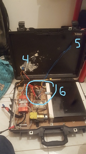
2- Please see the picture below with arrows. Could you please help to identify the items from 1 to 3? (If you could share relevant links for each component it would be perfect).
3- What is the current that is delivered to the motor? (or at least the maximum)? How do you define it?
4- The rpm of the Motor depends on the Current that delivered to the motor, right? So basically, if we control the current we control the motor speed, right?
5- I now understand that only ESC is cooled by water. This water is dragged from the ocean, right? Where are located the intake/exhaust of water?
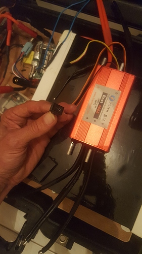
1 - forklift relay as a kill switch
2 - BEC - electric bicycle convertr to activate the forklift relays (because i bought accidentally high voltage relay)
3 - 2*BEC - converts voltage to 12V for water pump and 5V for receiver
4 - this is the receiver
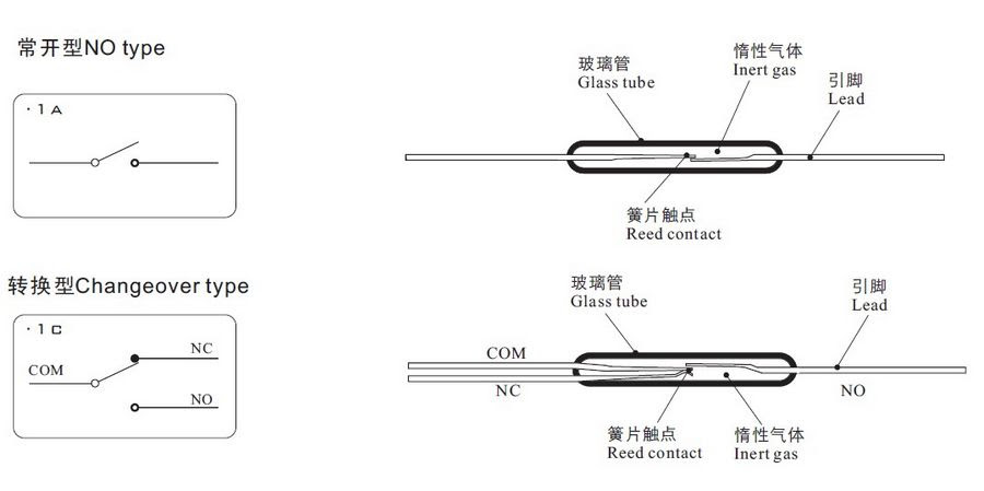
5 -It’s a reed switch (magnetic switch)
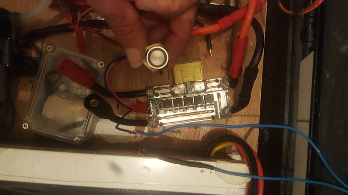
that’s how it looks now
Uploading: 20181203_002652.jpg…
6 - new power switch instead of 1, 2
there is a power button on the power switch and the magnetic switch is attached to it
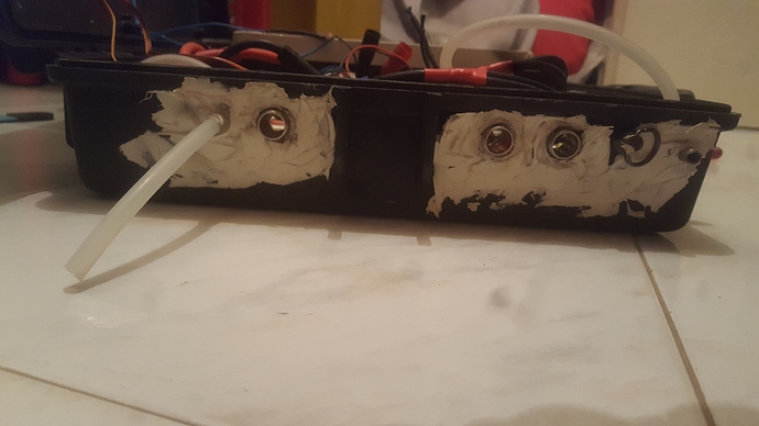
in the switch itself I do not use (just another hole that needs to be sealed, if the magnet is disconnected nothing works.)
the water is pumped from the mast next to the engine unit and the pipe rises with the motor wires inside the mast , un the box water entering the right left out
![20181203_002503|281x500]
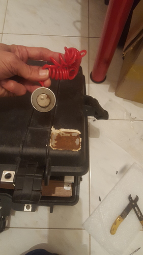
a thin piece of iron glued from the outside to connect the magnet
which activates the magnetic switch (whole system)
(upload://z1zr4rRMJWt0SVeSWrdaeGz0a7O.jpeg)
for the next build I just ordered a controller with a power button (same price) and then you can skip 1, 2 and 6
2 voltmeter and a current that I need to connect at some point (not any glue or silicone sticks to these boxes so I did not want to get involved with another hole)
" 3- What is the current that is delivered to the motor? (or at least the maximum)? How do you define it?
4- The rpm of the Motor depends on the Current that delivered to the motor, right? So basically, if we control "
the controller determines the power of the current to the engine
and you have the ability to program the controller to the currents that he will give (75%, 100%)
eventually you control the current with the remote
do not forget that my battery also has a discharge voltage protection controller (BSM)
@1113 I have the same Vedder power switch. Have you had any issue switching this off under load?
How are you controlling the switch with a Reed switch? I.e my understanding is you short C and NO to turn on then C and NC to turn off. So would need a dual channel Reed switch or use another small relay to get no and NC contacts.
you do not have to do what you mentioned
the simplest way is cut only one electrical wire, no matter whether plus or minus
the button of the switch will remain essentially open
and the magnetic switch only connects the wire you have cut
I have the button inside the box closed and not in use (always disconnecting the battery at the end of use)
@1113 interest the installation of the magnitic switch on an anti spark … would you have a detailed diagram for the connection … it interests me because less expensive than a kilovac…
i do not have a diagram I will try to prepare
today I’m out of time so I’ll try
Thanks for all the great feedback 
But can you tell us actual values? More a less what is the current that arrives to the motor? For example at 50% and 100%
