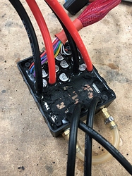
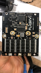
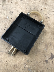
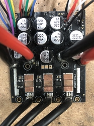
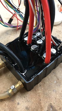
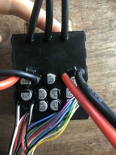
As you might know by now I have 2 Flipsky FSESC 200A 60V for my jet board. (double fun)
If I want to read both, do I need 2 Bluetooth modules, or will 1 work and connect both Flipsky’s together with the CAN bus?
Really good question , all I know is that you need to set one in master ( remote will control this one ) and the other one in slave (Connection via can bus)
As I recall you can put BT module on either one , as far as data I have no idea if you will get each one ( with specific data) or just one , I guess they will run exactly the same way
For sure you cannot run 2 BT module at the time on the same app on one phone
Try to look for: RT data dual vesc on the net
I think in metr there is a setting for multi vescs.
But i cant check it right now.
Vesc won’t connect over USB
Hey There guys.
Went to a whole lot of mess with this controller. Somehow my Vesc wouldn’t connect over USB anymore when I wanted to change my firmware to the no hardware limitations version. At this moment I discovered that the micro USB port on my 200a Flipsky water-cooled Vesc didn’t work anymore.
No problem I thought let’s do it over the BT module maybe the USB will work again after that. 5 min later I had the no-limit version on it and adjusted my settings to match the old ones and I was good to go. Then somehow I messed up and turned off the UART. So bye-bye BT connection.
At this moment the Vesc still worked okay it’s just that I couldn’t change or see any setting. After this, I tried the USB connection again with different computers and a hand full of cables but I just couldn’t get a connection. I thought of reuploading the bootloader but discovered that those wires where missing and that wasn’t possible (probably they could save 5 cents on the connector and a few wires).
After this, I measured the USB cable to make sure that I really had a connection. The multimeter confirmed that there was a connection but nothing on the computer would show up. No sound, no new devices in the device manager nothing… At this moment I remembered that settings form each Vesc over the Vesc CAN network could be modified individually for each ESC’s if their software is above 3.45. So I connected my Vesc to another one with the same software version and was able to turn on the UART again. At this moment I could finally control the Vesc again with the BT module but are still having no luck with the USB connection.
My conclusion.
- The USB port is not that reliable on this Vesc.
- Reuploading the bootloader isn’t possible because of the missing wire’s.
- Make sure you have the latest software on it to have a second connection possibility via CAN.
- Having the app setting on “PPM and UART” so the Vesc can be used with a BT module.
I hope this whole USB thing wouldn’t happen to any of you! But be beware that this can happen and it’s not easy to fix if your software is below 3.45 since the whole thing is covered with an epoxy rubber.
Had the same thing - I was onto flipsky and basically its a badly done usb connection! I manage to get my USB working through about 3 days of trial and error putting pressure on the connector at different angles.
Very frustrating!
Tips previously given to use a smartphone as a bridge between VESC and computer:
best explanation from @Giga : VESC - (BT) > Phone - (Wifi) > PC
The phone should work in tethered mode too (USB cable between PC and phone).
Why the whole phone hassle? You know that the vesc tool can connect directly with the Vesc with the Bluetooth option? It’s under the tap connections then select the last one BT and make sure you have the right address selected (can be difficult lots of BT shit around now a days).
Okay, today al lot of Flipsky problems again… 
I went for a spin and suddenly at the second battery, the Vesc just stopped working. I went to check it at the pier and didn’t see any fault codes with my phone. So I tried again it worked but I heard a very short strange sound every now and then while foiling (like the motor was struggling or skipping a step). After a second pier checkup I tried again but nothing the Vesc was completely dead no motor spin but a phone checkup that said everything was okay no faults.
At home, I tried again with the Vesc tool and saw that the PWM signal was coming in but nothing happened. I checked in the terminal for “faults” but noting showed up, then I looked for “fault” and saw the error "FAULT_CODE_HIGH_OFFSET_CURRENT_SENSOR_3.
I Googled it but not much luck only 3 hits… I saw that some year ago this was seen as a software bug and was fixed in version 3.55. So tried re-uploading an older software and even a bootloader but no luck.
I read as well that people were having this issue in BLDC mode and FOC mode. So I gave mine a shot in BLDC mode and the fault magically disappeared. I tied running the motor and by my surprise, it turned again but not smooth. I adjusted the settings and everything seemed to work again. It even worked good in a stationary test. I only noticed some slight increase in power, 4kW instead of 3.4kW that I had in FOC mode. But that could also be because I was able to get a higher duty cycle with the BLDC mode. Didn’t know that BLDC would run so different.
I still have no idea what caused this issue but I know for sure something has happened inside that Vesc that is preventing me from using FOC. If any of you have an idea what this strange Fault could be let me know.
-
The motor is fine and runs with another VESC in FOC mode.
-
All the connections are solid since it works in BLDC mode.
-
I can’t explain yet why the BLDC mode takes more power, I know its less efficient but this much seems too much. (will test with the second esc if its back to 3.4kW again)
-
I think the BLDC setting is just a bit less sensitive to current spikes and therefore accepts the error.
-
Hoping that banggood will help me with my warranty claim.

-
So far the Vesc has about 14hr or run time and a 25hr on time.
-
Will continue to foil in BLDC mode and see how long it lasts.
Okay the BLDC mode lasted 10 minutes  .
.
So I contacted BG but no luck, they said only a 30 day warranty on diy products and you guessed it… that passed.
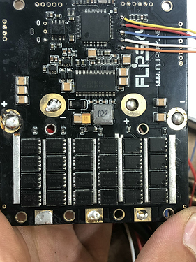
So I decided to become an archaeologist. And started to remove the rubber. To see what went wrong with the Vesc.
After I had removed al the rubber form the top and loosened the screws I used some compressed air to build up some pressure under the PCB to force it out. After that I continued to clean the bottom side of the PCB.
So far I have fixed the usb, that one had a loose cable inside and the extension PCB had one of the usb pins corroded away. The sensor fault isn’t fixed yet. One of the 3 current opamps stopped working. I noticed that the 3.3v was connected by a bead of solder to the 5v pin on the extension PCB under the connector. So some components where connected to 5v instead of the 3.3v. Hopefully my new current opamp will come in on Friday and fixes this issue of the error code I’m having.
So that is how they look inside 
We have 2 here for the new build. Let’s hope they will last longer than 10 minutes.
It is time to try HGLTECH ESC. It will not disappoint you. ![]()
https://www.aliexpress.com/item/1005001380664385.html?gps-id=pcStoreJustForYou&scm=1007.23125.137358.0&scm_id=1007.23125.137358.0&scm-url=1007.23125.137358.0&pvid=9fbd9eae-2c75-457e-b3ec-8be105342203&spm=a2g0o.store_home.smartJustForYou_650142565.5
What MOSFETs are on there? I would love to test one. Seeing the 3 shunts per phase looks like a good start.
Replacing the current measure opamp solved the issue 

The Vesc works like normal again and I put it in a nice new coating. Hope I don’t have to repair it again.
Also connected some wires to the microcontroller to upload a bootloader if ever needed. if someone needs the pinout of those contacts just let me know.
You made quick work of that! Not sure how many people could have done the same.
Thanks!, I actually fixed it last Friday just wanted to keep you guys posted. It still took a lot of time though. A few evenings to find the problems. Now I’m a Vesc specialist 
Did you correct this issue as well ? Is this issue present on any FSESC 200A which would mean it is a design error ?
Solved that 2, was just a crappy solder joint in combination with corrosion that somehow made a connection. Just make sure to keep this small connector PCB dry. A epoxy coat on the bottom won’t hurt and if you are careful an patient enough doing the top between the connectors would be super. I think because of the small space between the connector plastic and PCB water would stay there longer if it gets wet. Therefore have a longer time to make sure it corrodes your pins where you don’t see it at all. If you don’t use the 5v or the 3.3v you could also take these of the PCB. And just have one supply rail on there.
Would you have a before/after type of pict to locate this potential weakness ?
I’m not sure, ill look through my pictures. Ill have to do a second one so ill be sure to capture the coating process.
While my VESC went bad I ordered a new one, if it were to happen that I could not fix it. That one came in today and I noticed that they have changed some things, at least from the outside. There are now 2 diodes across the battery input wires and the capacitors have a higher voltage rating but a lower C. So probably there were some issues with input filtering. The diodes will take care of some strange voltage spices but the lower C I don’t know why they did that. hopefully also some upgrades under the rubber but we will see when it fails (hopefully not).
