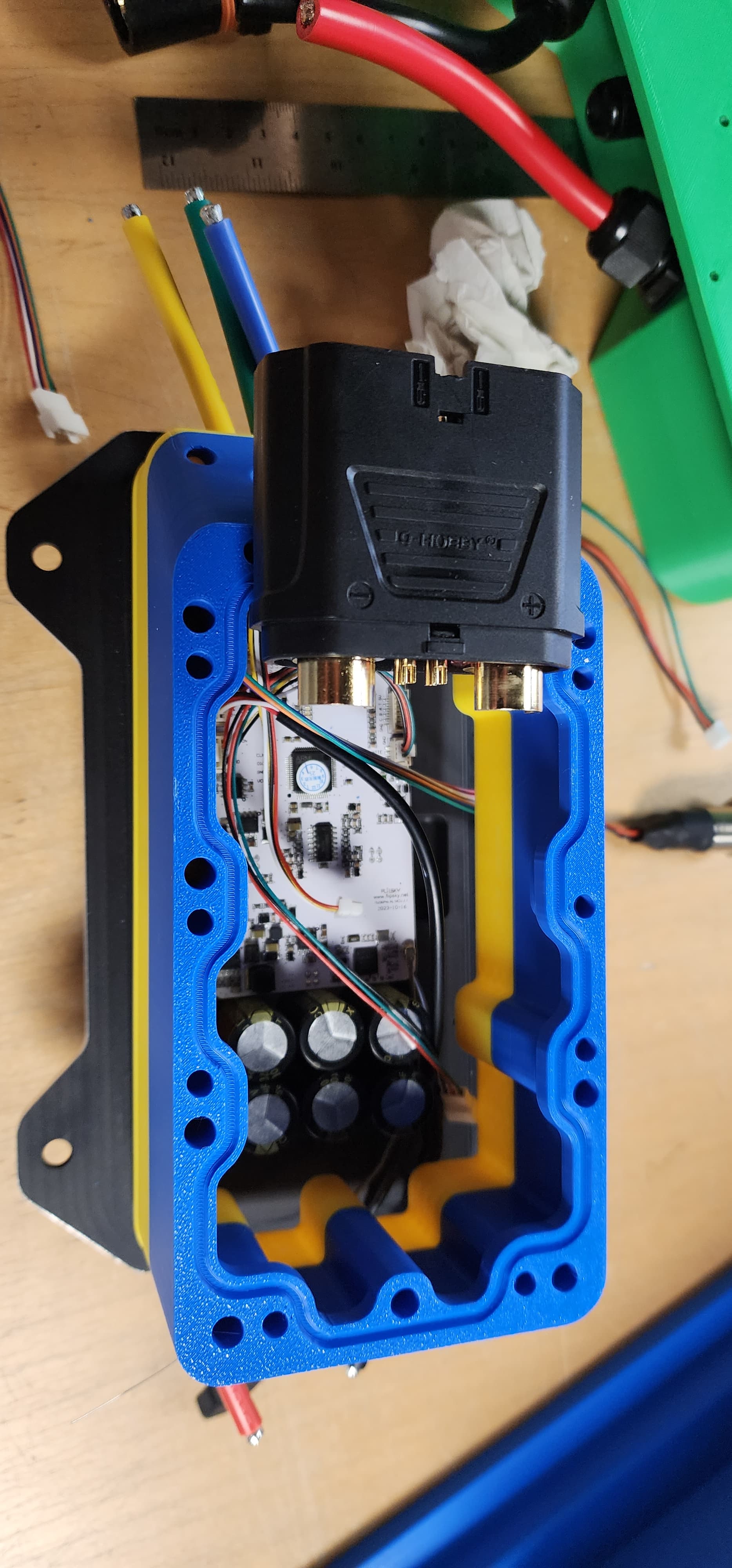
I have the case printed out of petg, i ran out of asa. That will complicate things later but I might still make a mold and cast the cases out of Task 21 or simular urethane resin if other people want some (wait till i pressure/vac test this) . Intergraded tclass holder works but the fuse i got appeared to be used so I have another on order. Internal wire routing looks good, still kinda wish i would go full buss bar to tighten up the tolerances a bit more predicatably, I’ll need shims if i just solder wire to the output nickel strips.
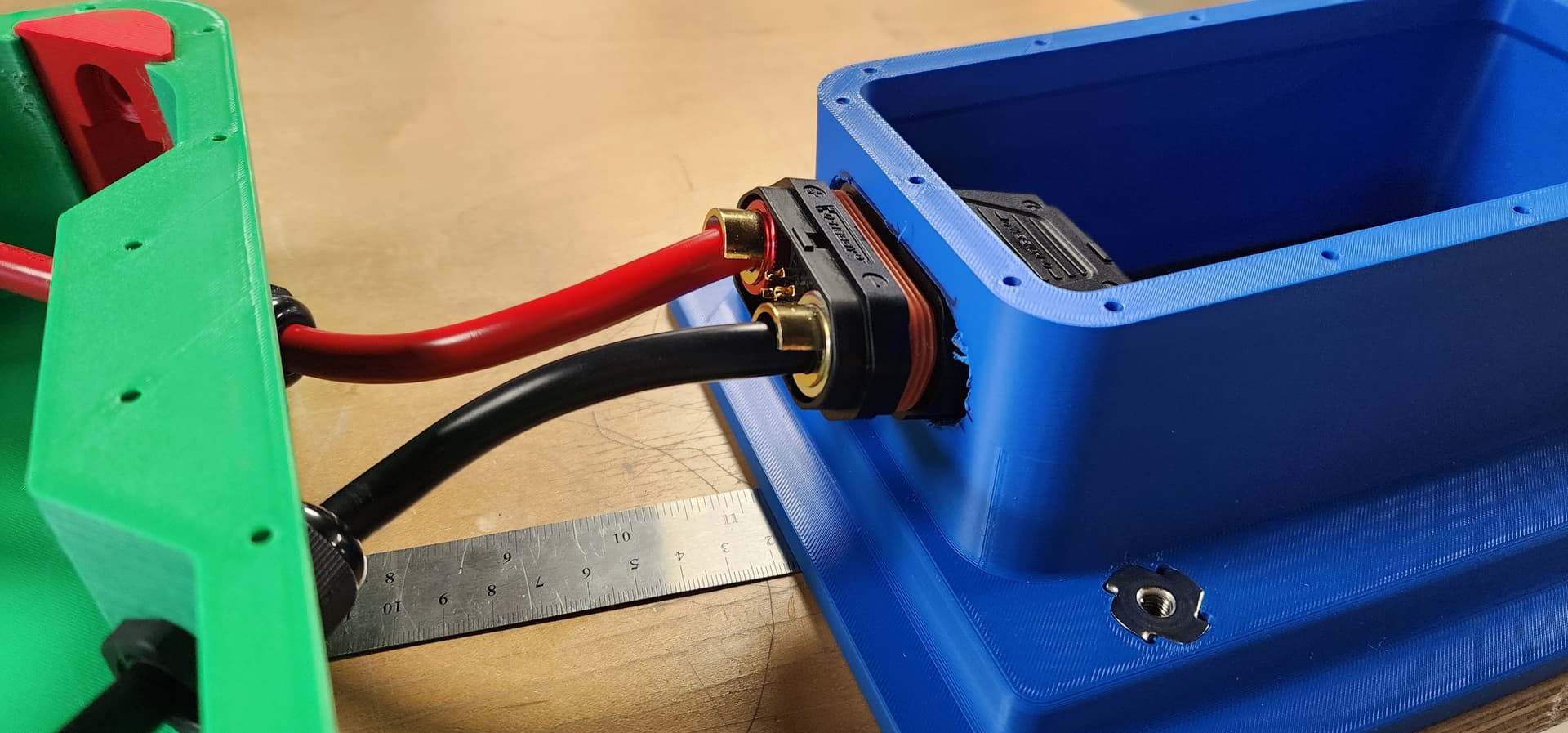
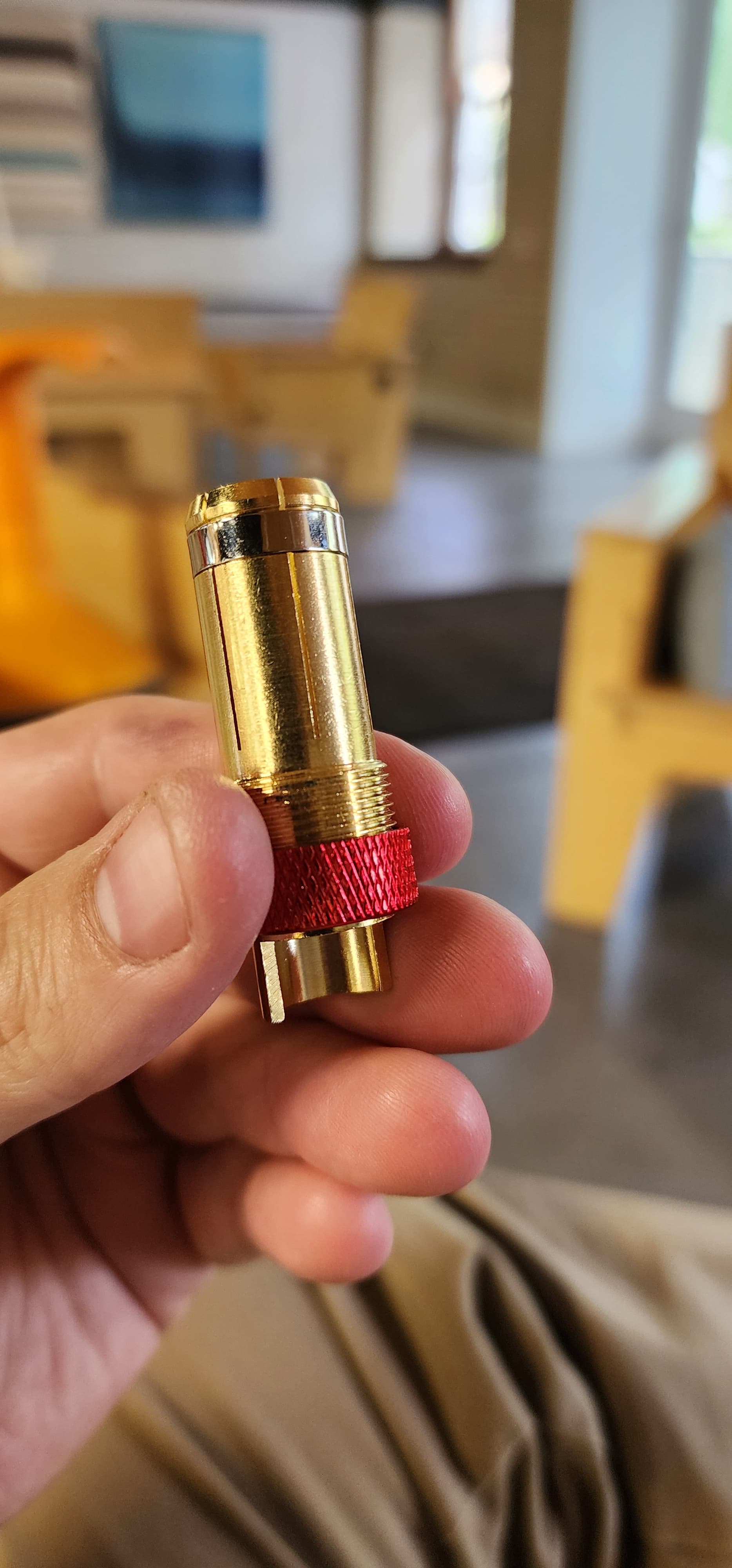
Now onto the big problem, the QS12 connector is a bit too big so I’m looking for a connector with 200 amp capacity that has antispark built in that is a stud connector so i only need wires on one side. Anyone have any suggestions on finding Cinderella. Oh i also wanted 4 aux connectors so i can route CAN, and it should be water proof… so yeah Cinderella.
The QS8 van take around 190 amps (I believe), and is antisparc too
The QS9. had “data” cable options too (4 extra small pins) between the plus and minus.
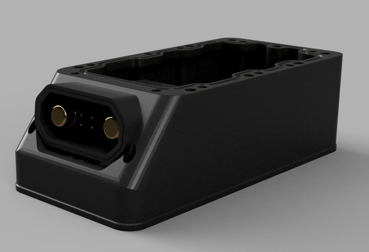
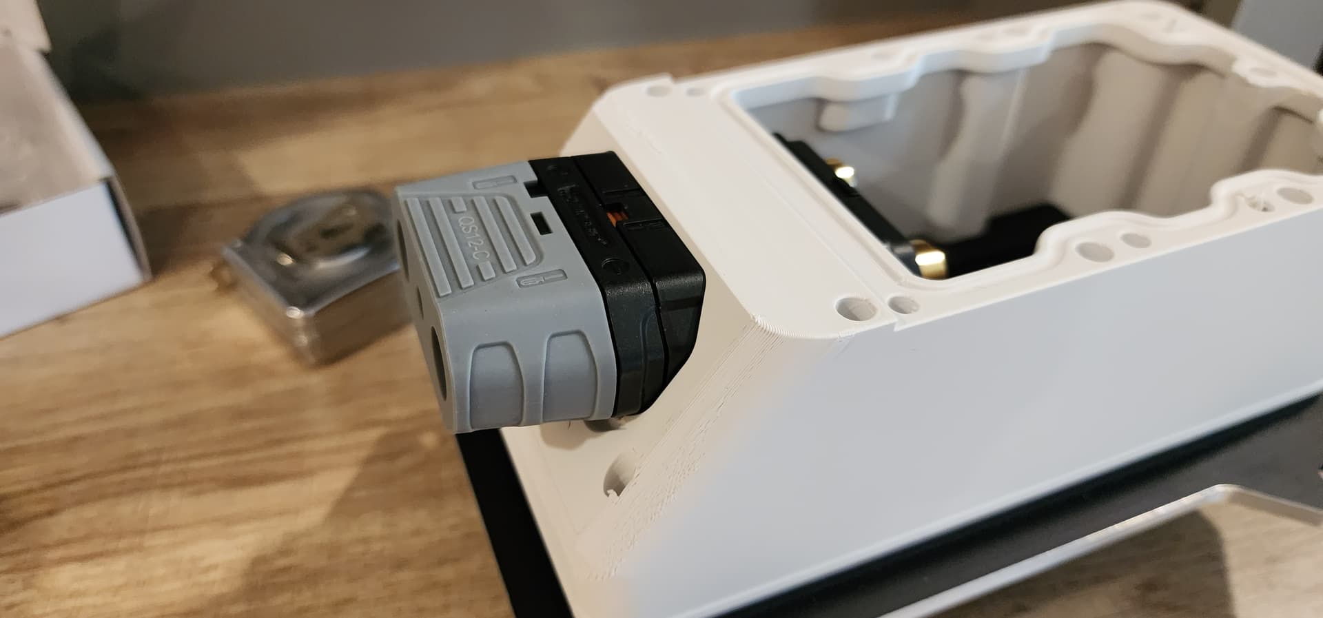
Interesting. That being said it give me an idea. I think I’ll try to turn the Qs12 into a panel mounted connector as the qs9 isn’t water proof. I have the box mocked up but my cables aren’t quiet flexible enough as the marine isulation on them is quiet thick.
A slight upwards pitch to the connector seems to work but i haven’t mounted the vesc up yet to check clearelnce issues.
Edit: Just did a test fit… i can get the adapter to fit but there’s not going to be much room. I might need to comprimise on both the 4awg and the connector. Just not enough room as i also haven’t thought about the power switch yet…
It does get tight in those Flite-style esc boxes with 3 phase wires and two battery wires and the receiver. You may want to leave a little extra motor side phase wire length too. If you need to swap out a failed esc at some point (which is a very real possibility) having the available wire length makes it much easier. I’ve done two of these with a QS-8 connector and just 8 awg wires.
Are you making two boards? You have the flite adapter plate and then your own version. If you’re interested I also have a version of that flite adapter plate where the phase wires come up at back end instead of along the side.
I think I found my solution for the wire issue. I had some EPDM-insulated #4 welding wire left over from a solar battery install I did a while ago. It’s way more flexible.
I’m currently building one board but hoping to build another one, and I’m figuring out all of these little integration issues. It’s death by a thousand cuts, but I’m making progress. I’m 95% of the way to building the pack.
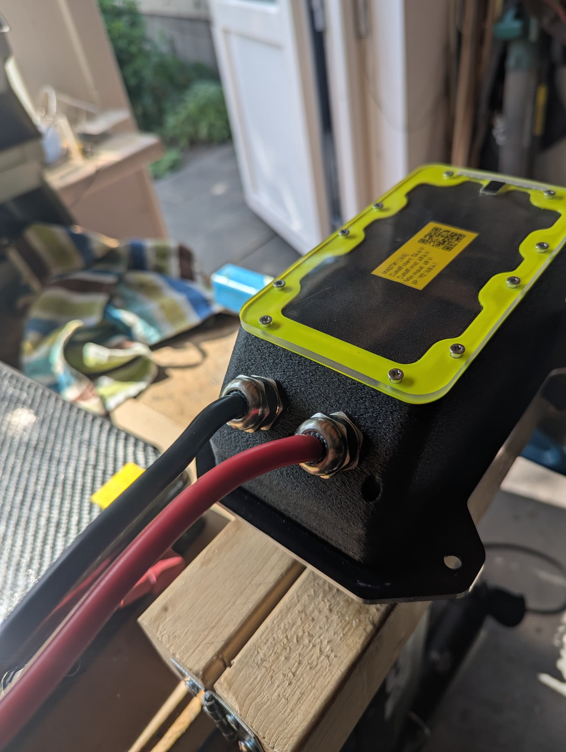
I got the mast mount from Kian, and it is very, very nice. I’m not sure about the rear entrance, but I do plan on keeping a service coil inside the esc box. Millimeters are starting to really matter. On that end inside the box i will use 8 awg, little to no need for the bigger wires on this application.
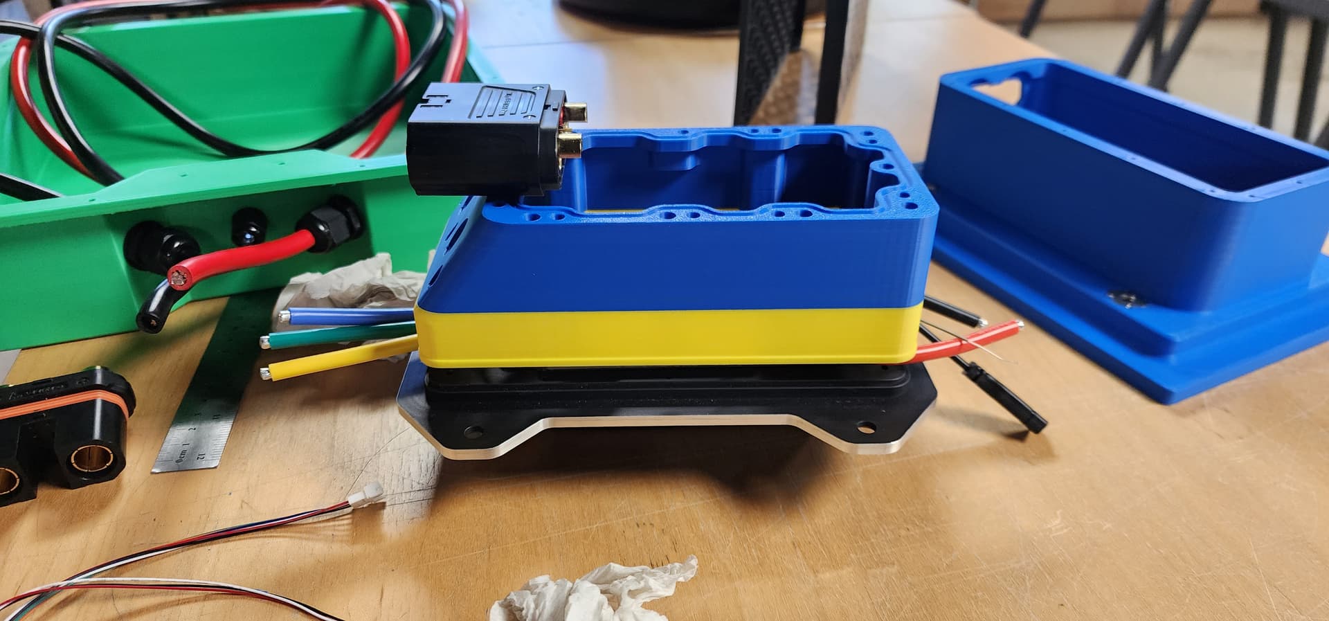
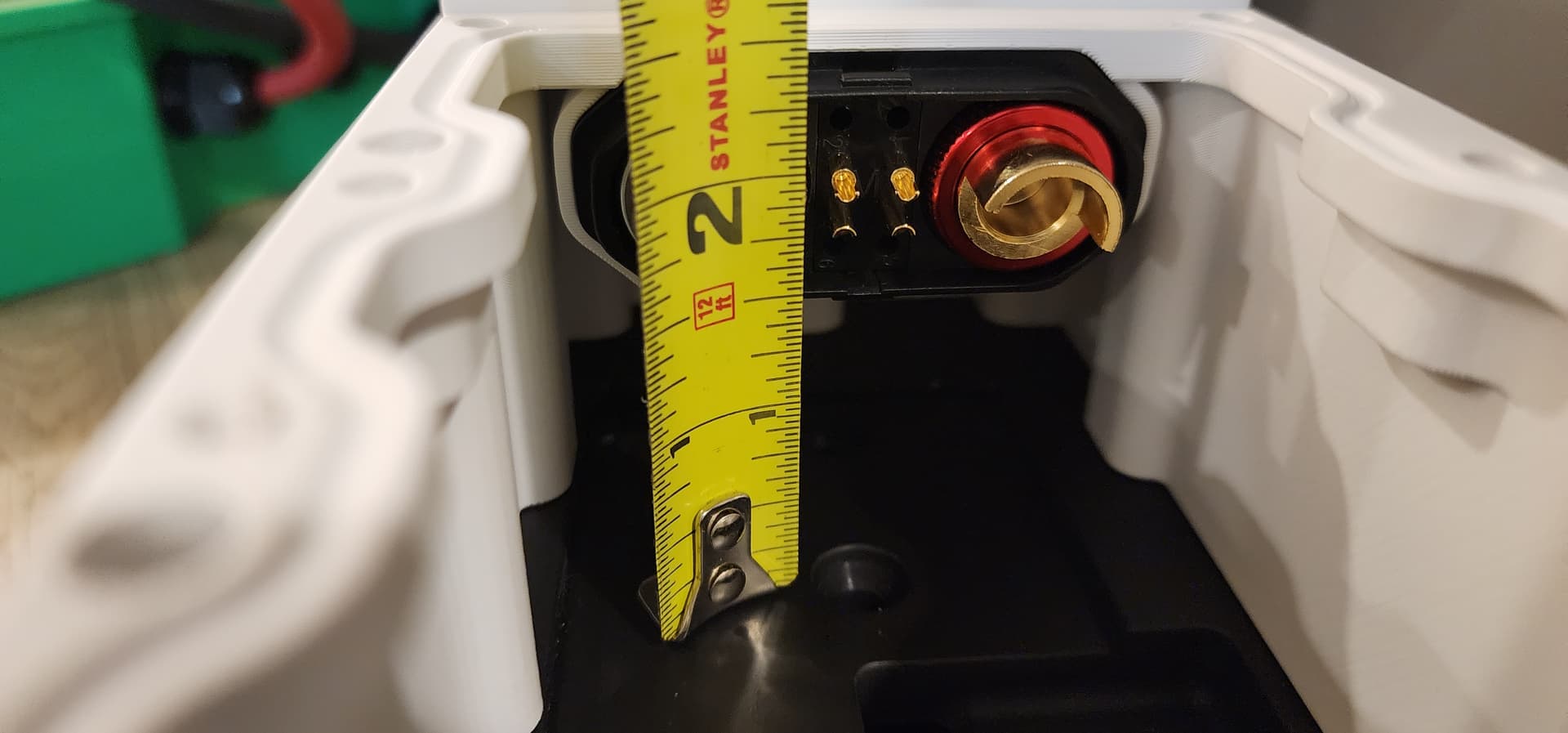
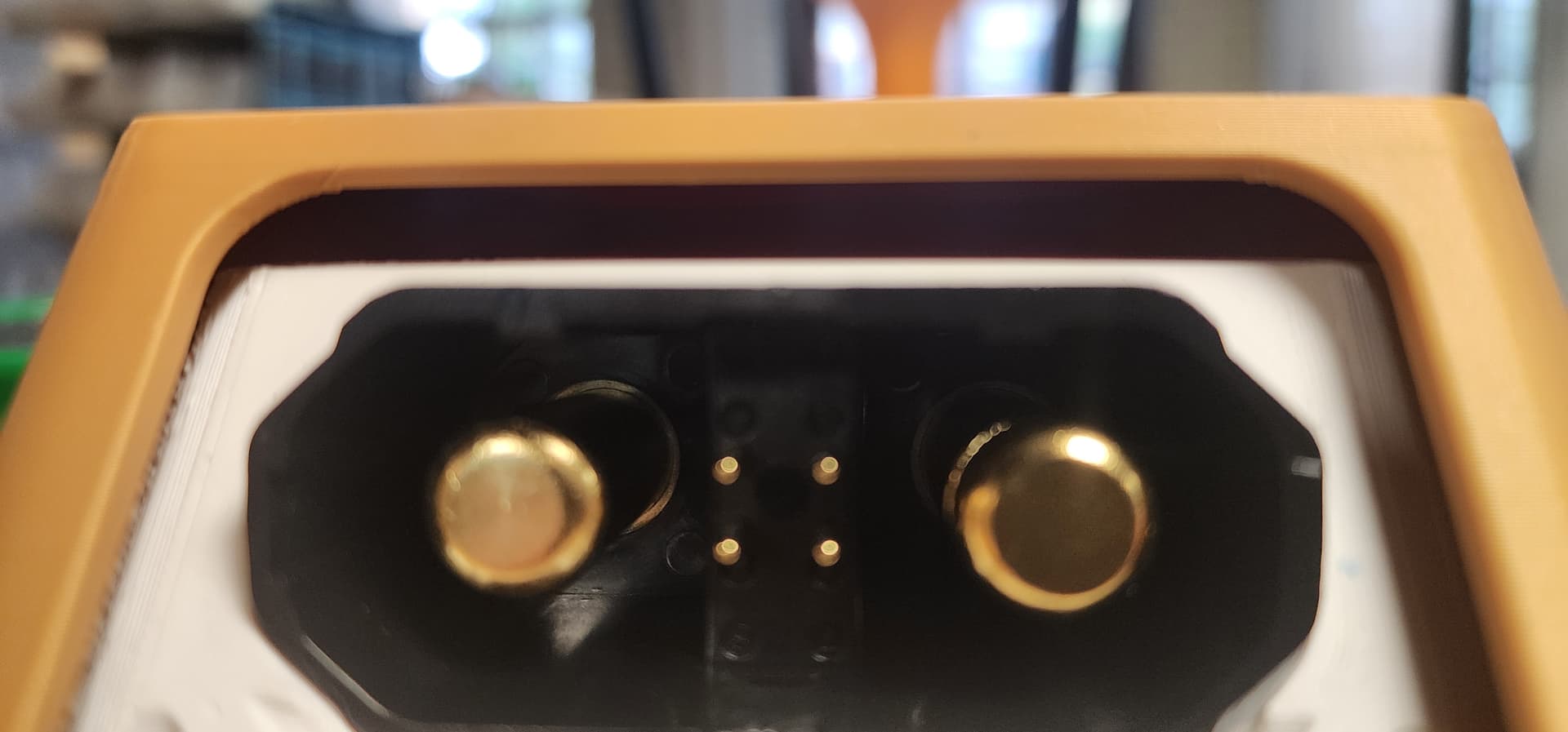
Anyway, here’s what I’ve come up with. I need 23mm of height to clear the Comm port on the ESC with the cables plugged in. I just made it, but I would like to make it a bit better. I need to know how much space is available on a fliteboard, as I want to continue to try and make this compatible for the challenge. I know @Kian made his with space to account for the top, but with the connector, I will be shrinking the opening to the area behind the connector and shifting the entire thing up to reclaim as much space as possible.
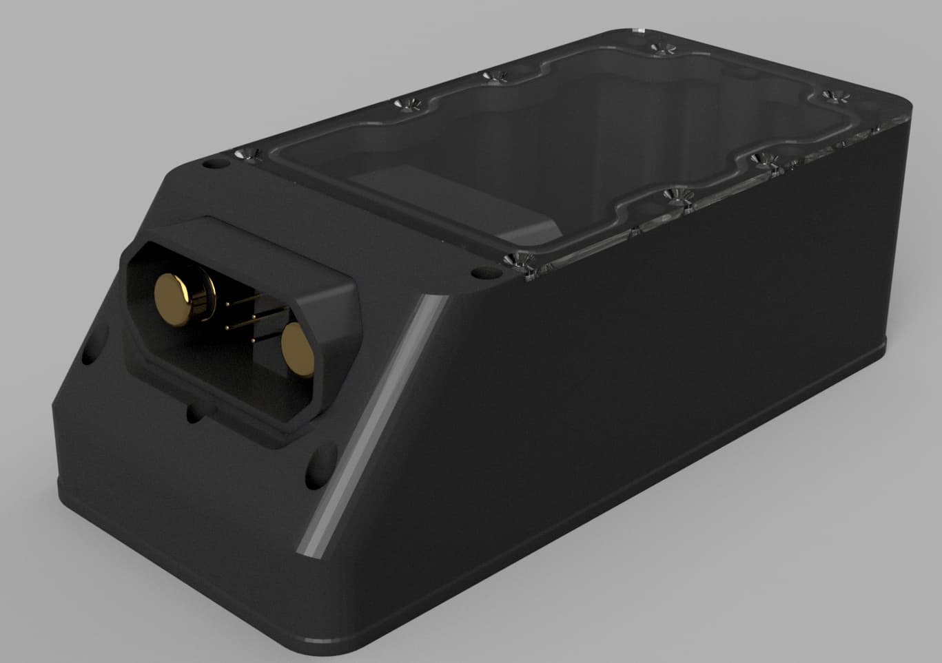
So, a little fine-tuning and some optimization, and I think I have a new test print. Hopefully, this gives me what I need so I can start to actually build the battery side. Going with a clear acrylic top, because why not? I will likely be abandoning the on-off switch on the 75200 Pro V2; there’s just no space for it, which is a bummer.
Looks nice.
We tried this some time ago but opted for the simpler solution: 2 waterproof glands.
The problem with this setup is that the soldering connectors are too close to the VESC (75200) capacitors.
Another “problem” is that it’s hard to reach when the box/mount is inside the Fliteboard.
Also, the strength of the box itself might be an issue too. Forcing the connector in and out many times won’t do it any good.
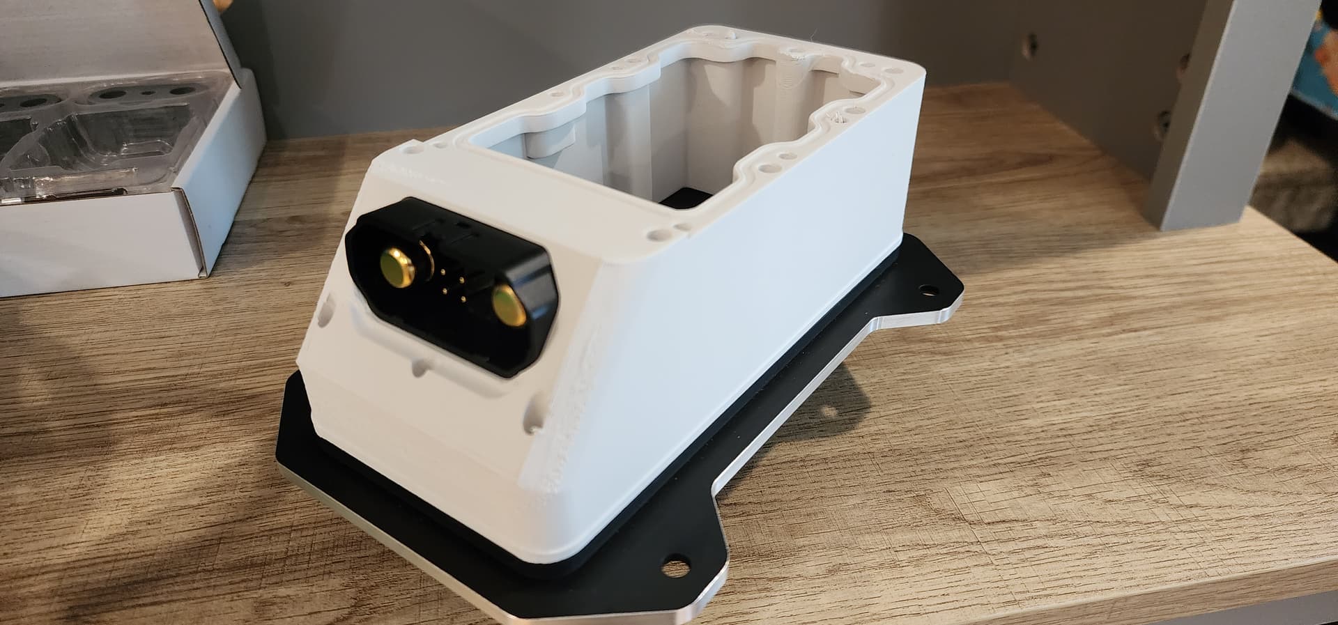
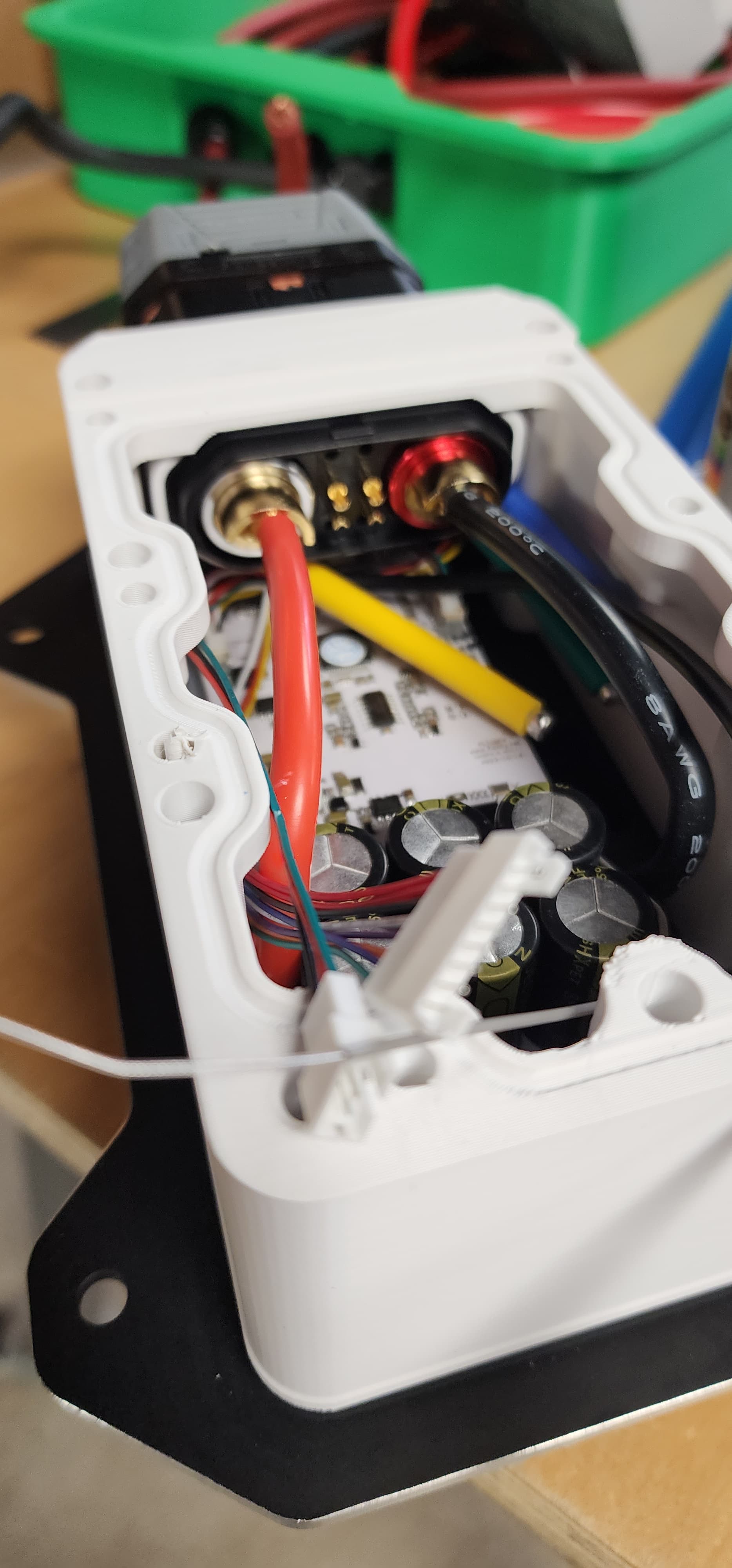
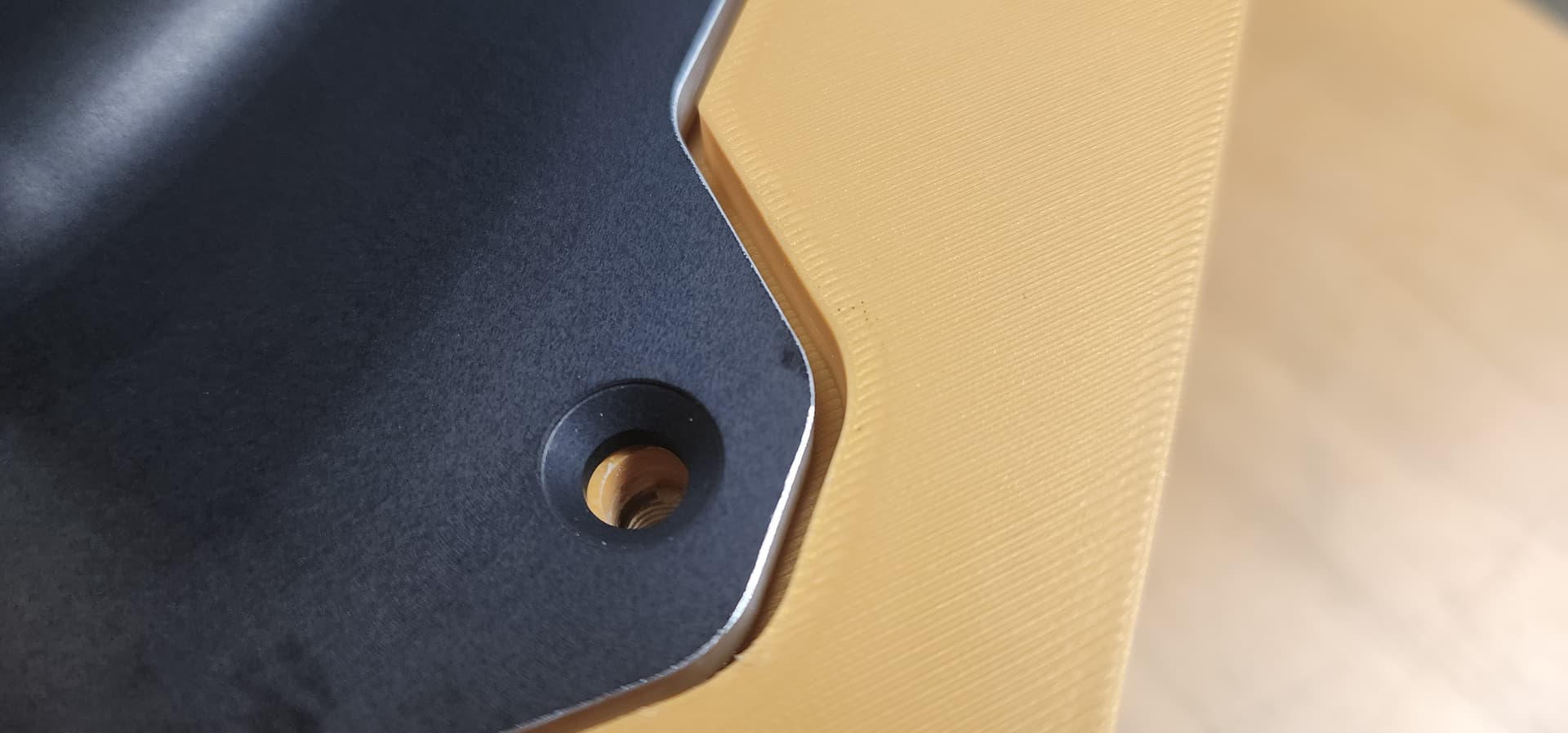
Great insights, I’ll add some reinforcements or maybe print it in ppa-cf. As I currently have it, this will be epoxy in and there is an internal socket to spread forces. I’m also using the male side on the escbox, i don’t want exposed power poles on the battery side and it makes it much easier to glue it in. Since it’s nylon I’ll hit it with an oxygenated flame first to enhance bonding like i do with ski bases. I am concerned about the amount of space in the box so I’m printing a test peice. I did move the roof up 3mm to make some more room. I have 26mm in the worst case scenario to the surface which should be enough as I needed 22mm.
I have some thoughts about access to. Thinking of adding a pull to the back of the connector. There are also some dedents on the connection to lock it, those will be ground off. As for the access hole in the board, I think it will work…ish. I’ve based that off my percision calibrated eyes so it’ll probably be off by a milimeter.
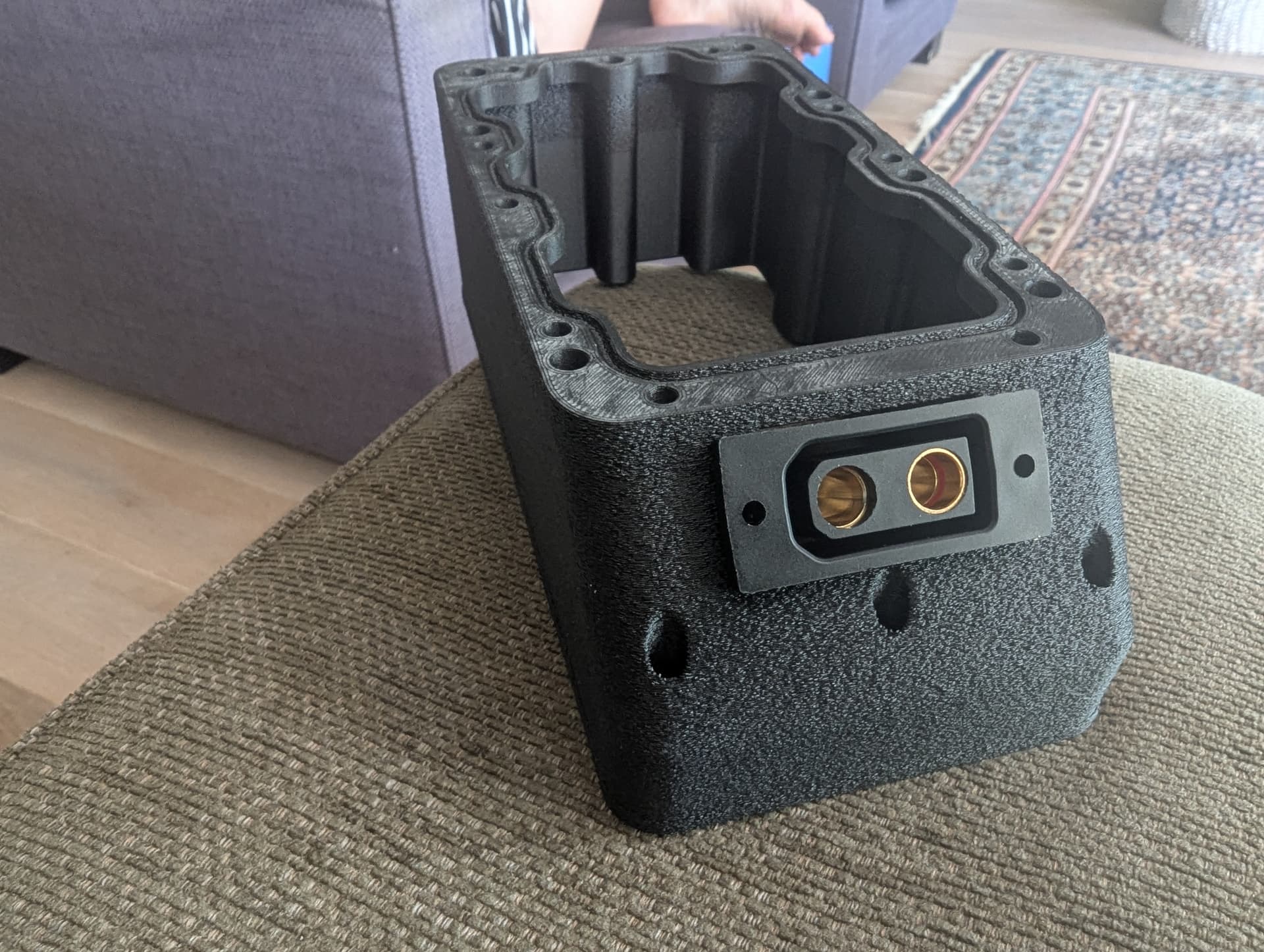
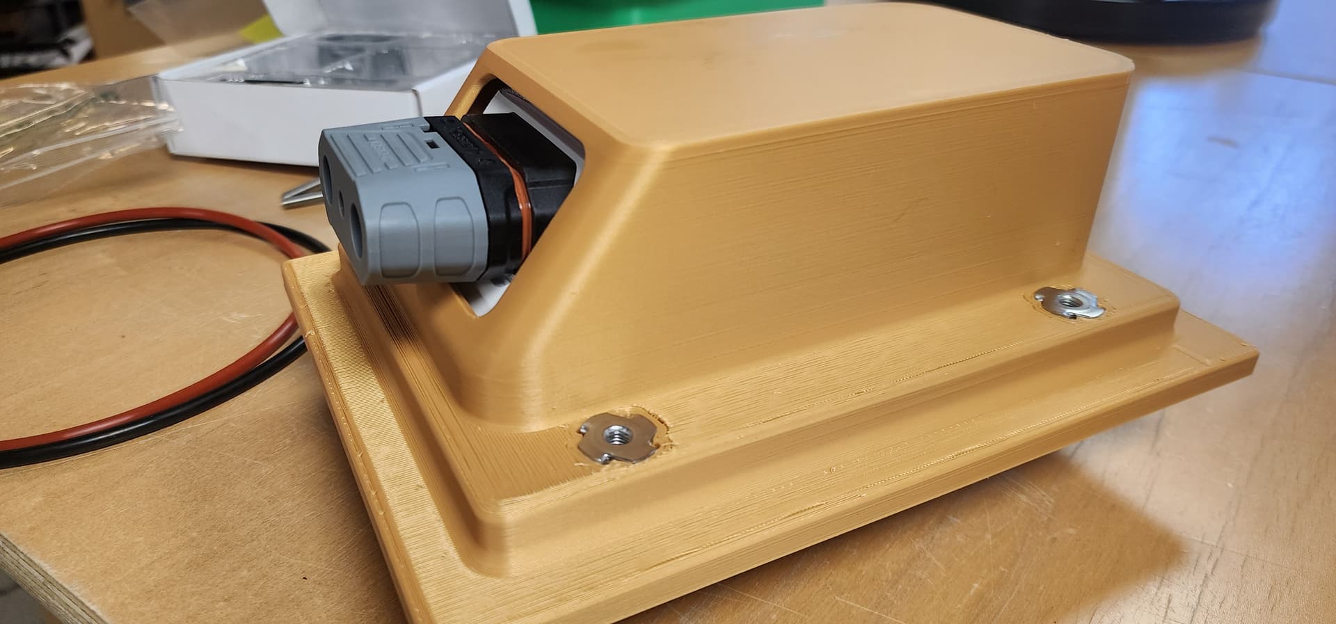
Test print is done, looks good. Printed it out of ASA and it easily strong enough with the extra reinforcements. Its a little tight inside but should be doable. But due to a ridge on the qs12 the connector had to be inserted from the inside which isn’t a huge issue.
I will be putting a screw together lug set inside to make it easier to service. Just need to fit my phase wires in here now… and a receiver… It’s getting tight but still feels doable.
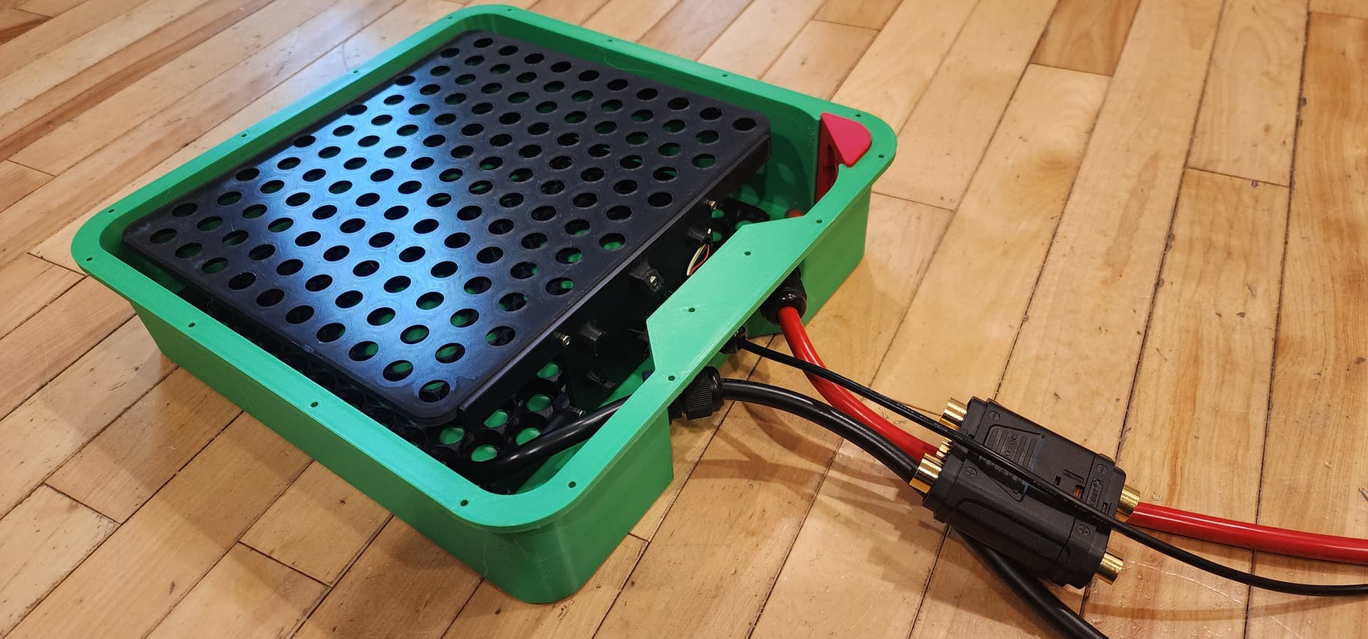
Started to finally assemble the battery. First timing using a flpsky sw-1 and it doesn’t seem terrible. The foot pedal needs a longer wire and the single hand one that came in my kit is a bit busted. However the core of the unit seems to work well when paired with the correct battery. So wish i would have gotten the plug in model but i bought this over a year ago so… its super good enough.
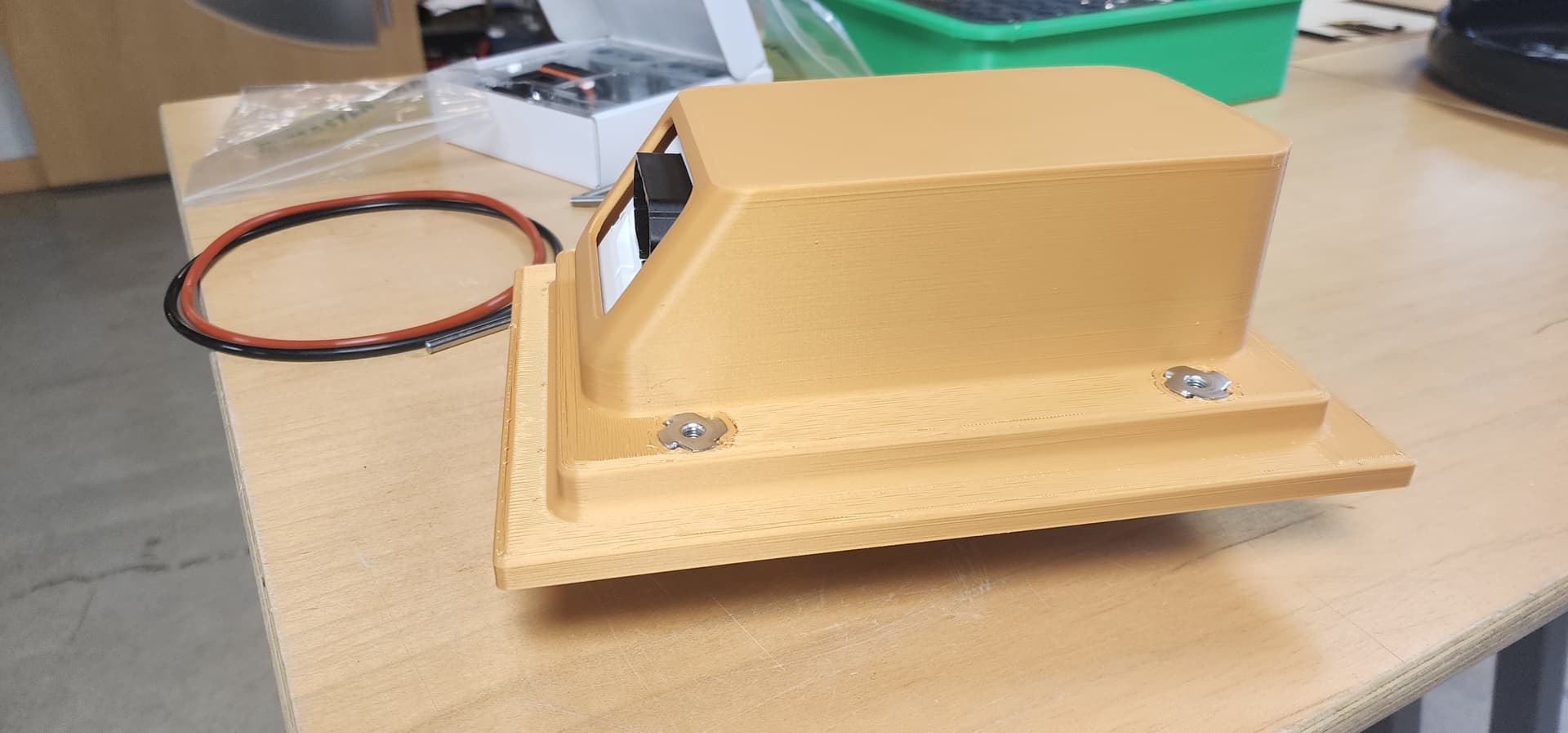
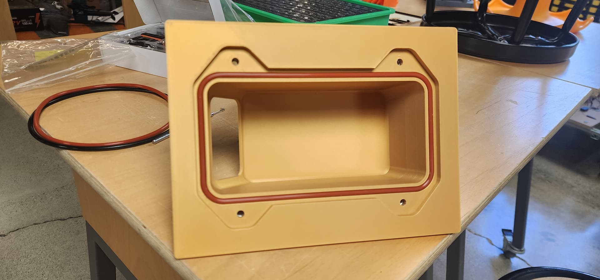
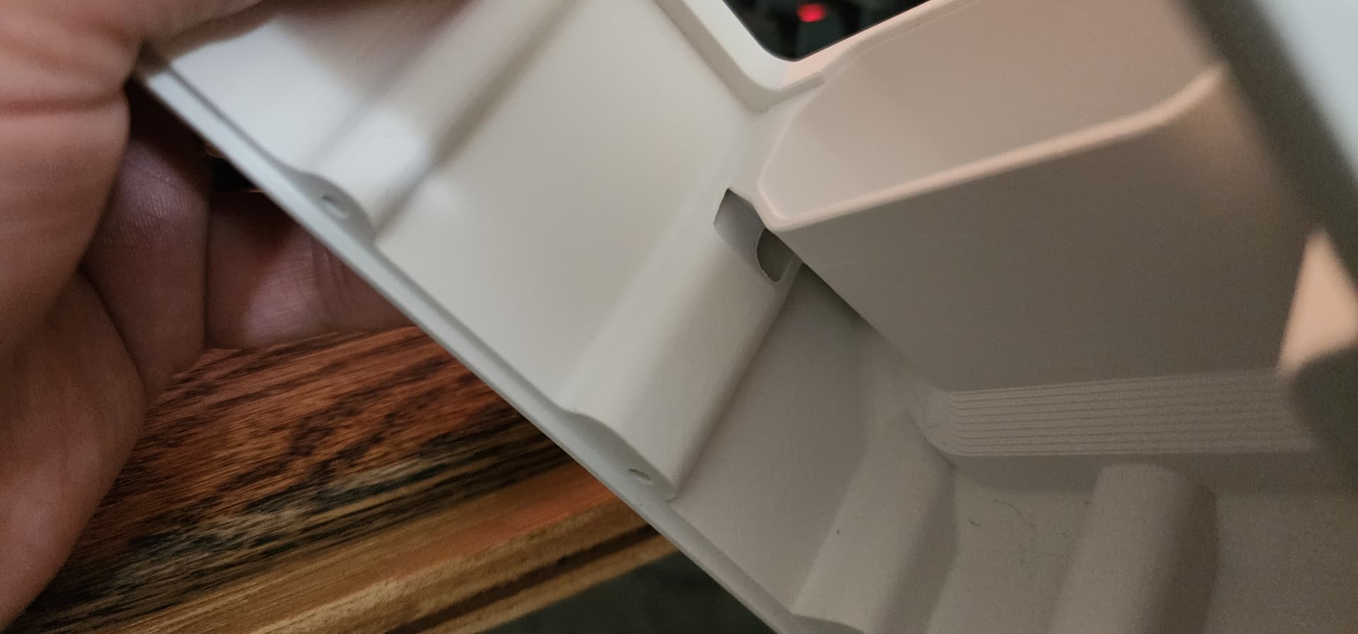
Test fit the new tuttlebox. Looks good. I went with a half dovetail to retain the oring. Soft silicone high temp seems to mount up well. I need to tighten up some tolerances around the edge of the adapter. I’ll seal this with a 2k clear when finishing the board itself. Its a really easy way to seal prints which i learned building skin on frame kayaks. I done have aquestion on carbon thickness, i with ski/snowboards. How much extra thickness should i account for if i want the adapter plate surfaces to be level with the board when finished, ballpark?
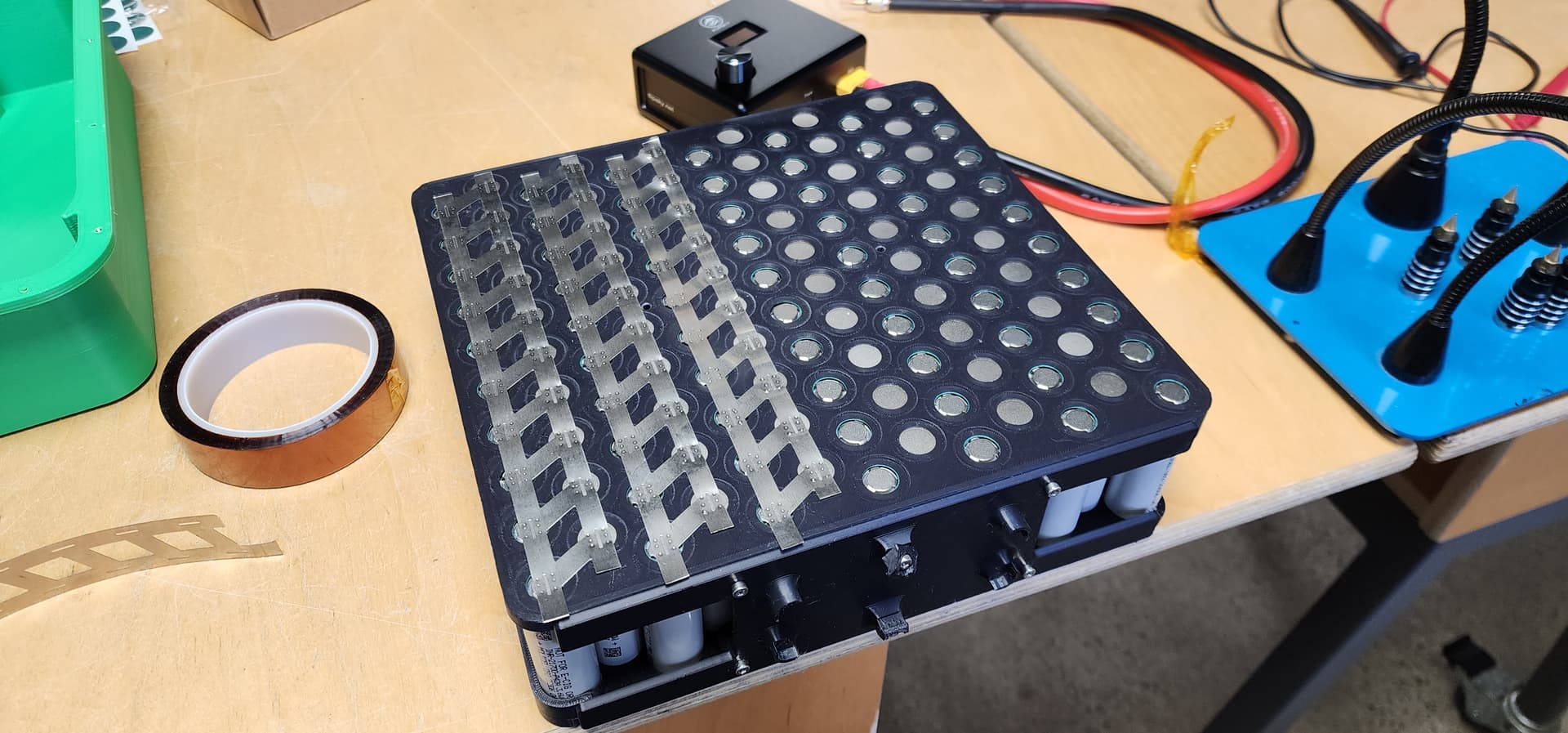
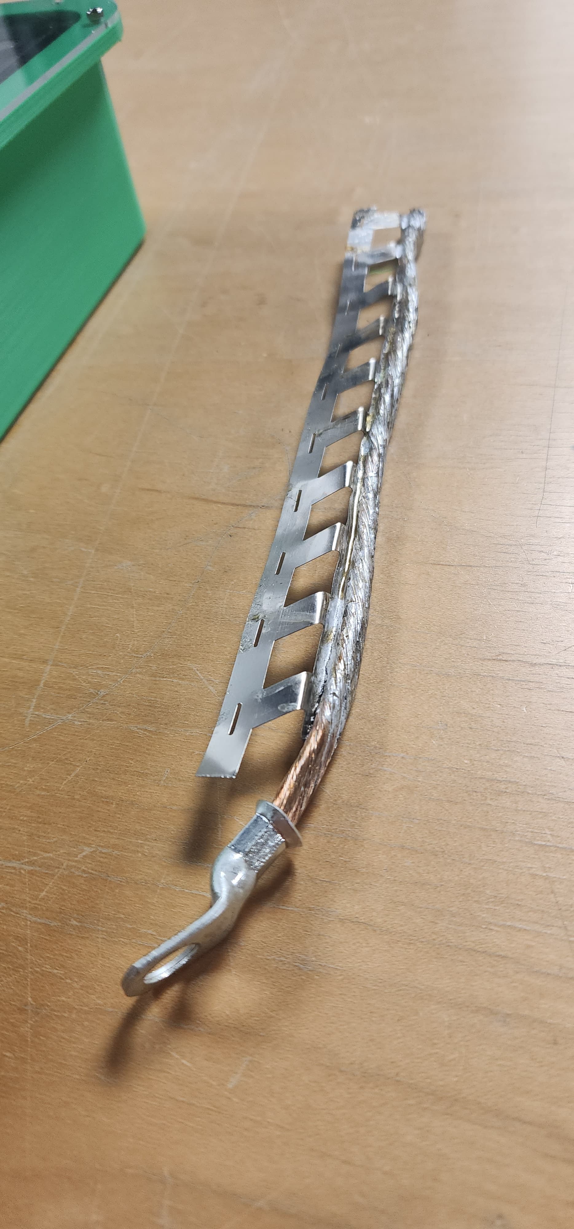
So, i need to rethink the bus bar design. I was going to use copper cable but i wholly underestimated the amount of heat a 4awg cam can sink. I had to break out a torch and the results are… meh.
I think i have some copper bussbar stock kicking around but given my new found respect for coppers ability to sink heat i suspect i won’t be able to spot weld or solder to it. I’m also concerned about the weight of the bussbar being supported by just the nickel strips as these will be cartoonishly oversized and will make the pack much heavier if i have them.
Normally we would bolt to this so i was thinking about doubling the strips, drilling thru both of them and taping some m3 or m2 threads. I was trying to avoid ridged busses due to the bend needed to reach the t-class fuse but i can insert then together now in this design. Any thoughts?
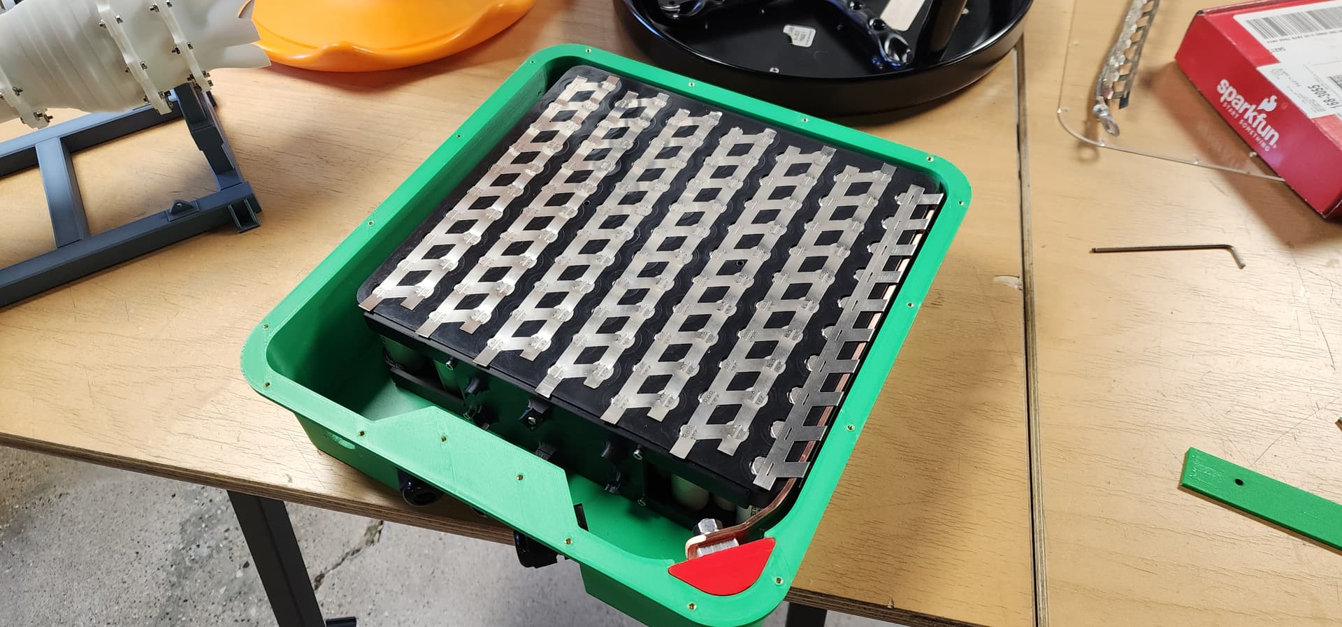
Ok, divided to order some bus bar stock. 1/8" x 1". Still massively oversized, but it fits. I’m going to drill into the isolator lips and install some heat-set inserts. I’m trying to keep with the same Ruthex inserts I’ve been using, but the clearance to the cells isn’t great. I might swap to Voron spec ones and add a backer block too. I also have a small issue with the length of my strips, which means I will likely be welding a backer strip on top of the cell tops. On the busbar side, I plan on using a button head M3 or M2 if I can find a tap for it.
On the upside. I think this time the file is finally ready, and I have had plenty of time to perform destructive tests on ASA. I just need to figure out how far up the mast I want to have the motor and get to mounting the power unit. I have a FR folding prop, but I heard that the shrouds make the foil a bit more stable and safer. Before i go model a new duct i looked around but i didn’t see any sort of standard for prop height realitive to the foil. Is there a recommended shroud and related spacing associated with that?
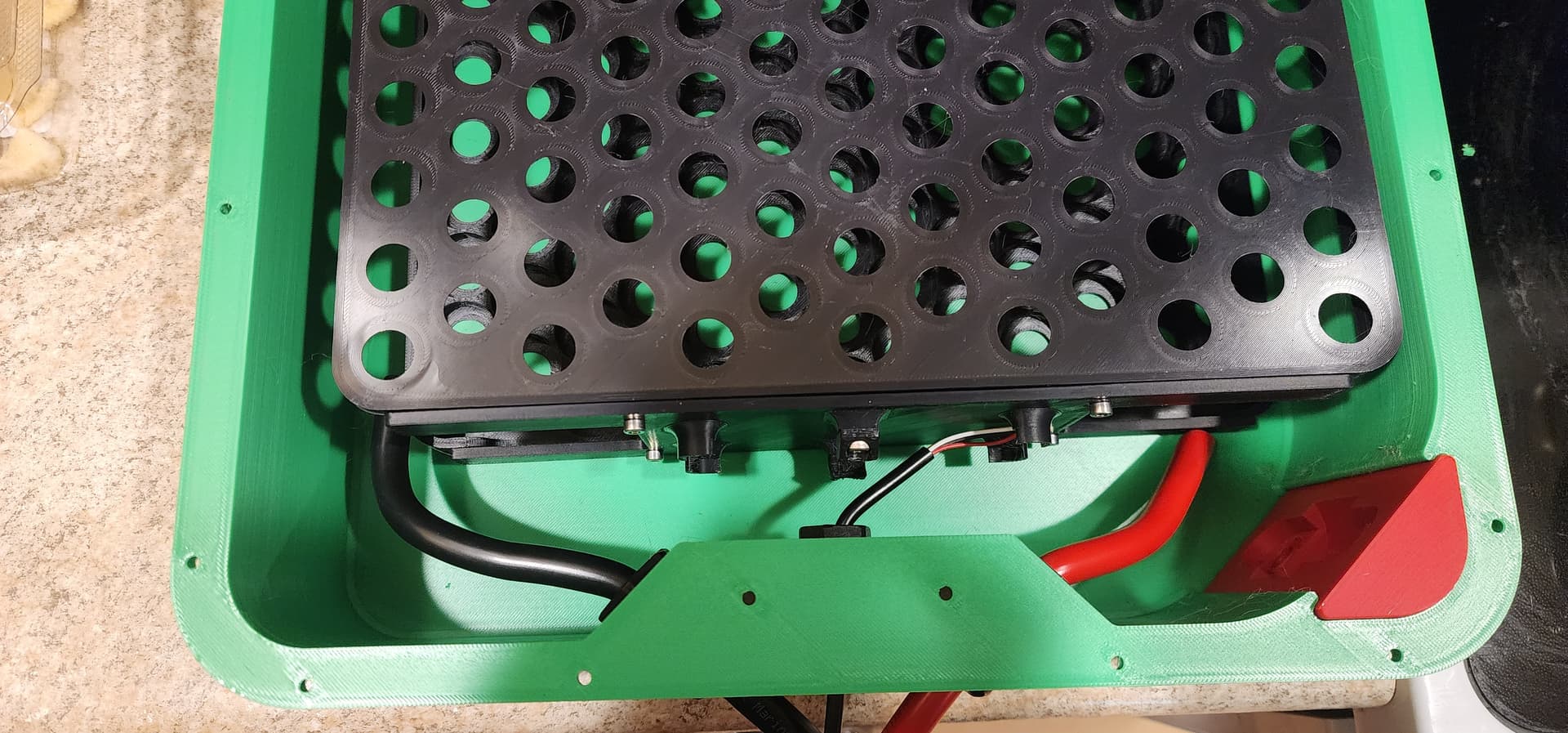
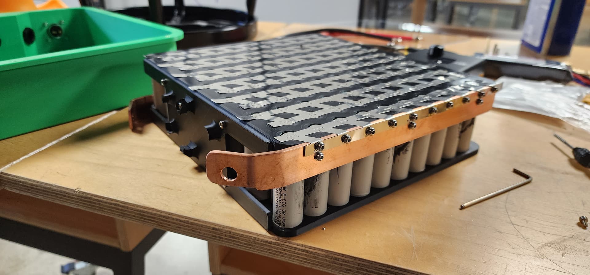
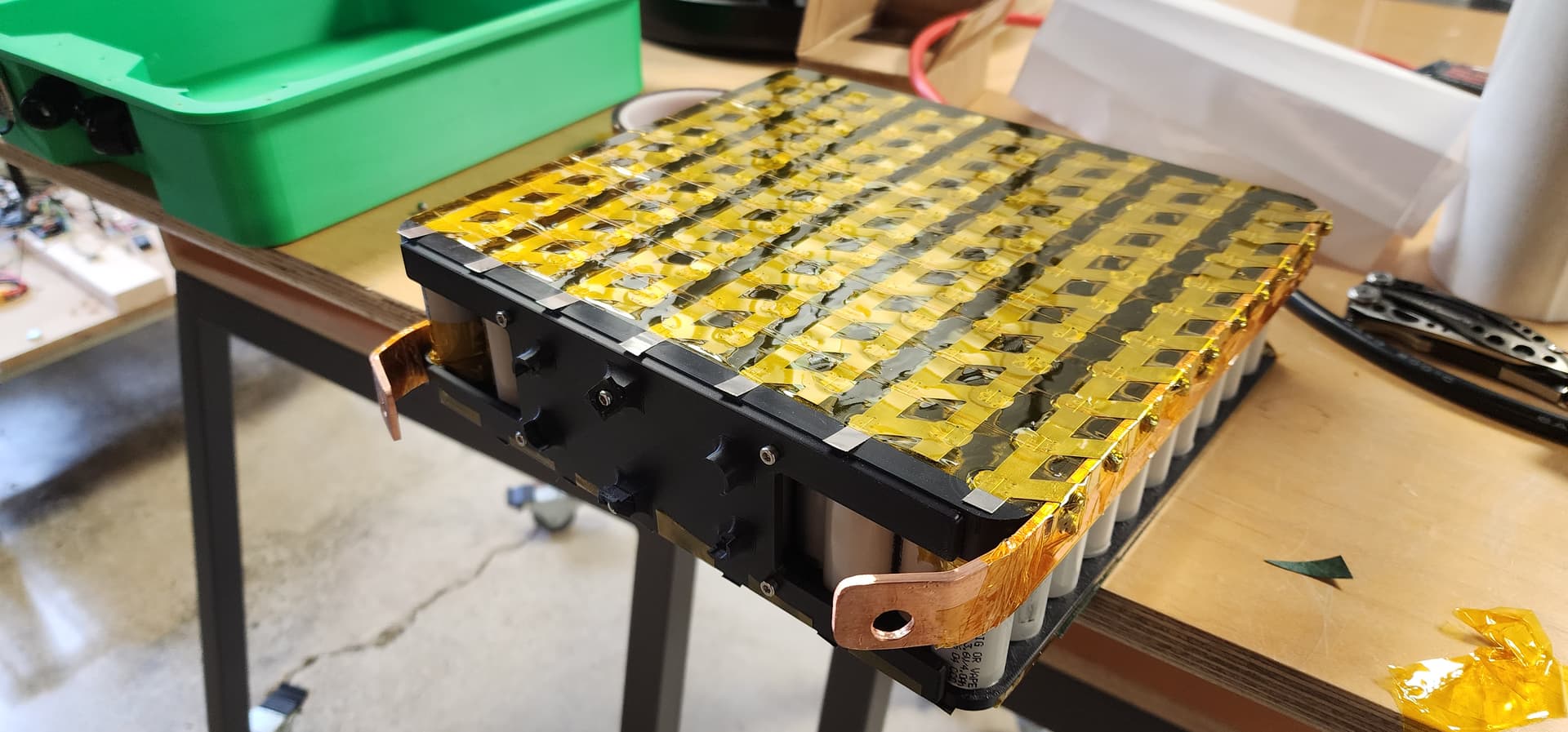
I also made some bus bars and screwed them all together. In hindsight, I should have made the fuse holder part of the battery tray, but it still works. Got it all wrapped up with fish paper on the bottom. Just need to make some spacers. To ensure it doesn’t wiggle around in the case.
The choice is, of course, yours. However, I recently switched to PPA-CF printing because my ASA and ABS+PC battery cases started to crack along the layer line after a year.
Looking really nice!
Not sure if you did this already, but you may want to add some fish paper between the bus bars and the side of the cells where the bus bar is folded down. Particularly on the batt + side. The outside of all the cells is negative and only has a thin plastic sleeve covering it. I wouldn’t want the bus bar to have any possibility of touching the side of a cell!