Hello high speed prop…
13 Likes
I was easily able to get an H105 profile on my 8cm chord 3D printed propeller without increasing the thickness. If I went any thinner i would be losing L/D.
Maybe it flexes under load, but why is this bad? Don’t you want to get as close to an elliptical loading profile as possible? i.e.decreased tip loading. (look up oswald efficiency in your aero text book).
Or just look at the wing of a 787 while it is flying.
Surface roughness: would like to see some data for this claim as well. How do you know you aren’t renergizing the turbulent boundary layer and preventing separation or a laminar separation bubble?
Are we not operating at a totally different reynolds number than your race boat? Why does it matter if the propellers dont look identical.
1 Like
Did you tested the 150 model ?, I looking for a good alu prop, since now all the one found are too large diameter, any suggestions ?
Do you still have it ?
I just wanted to ask for a bit of help with JavaProp if anyone here can help.
- there are now new value fields for Shroud Chord and Shroud Angle. I can guess what these refer to, but what are the units here? Can anyone confirm values for that?
- Regarding how to apply the generated models to the spinner: I know it has been discussed how do close these geometries. As far as how to join them to the spinner, what is the intended method there? It seems that the width of the blade is what follows the chosen diameter. But then what is the best way to join the rest of the surface to the rotor other than the midpoint? I assume it’s not intended to be “warped to fit” so as not to change the profile. Or is it? Do we continue a rough estimation towards the spinner and not worry about being accurate? Sorry for all the what-ifs.
Thanks to anyone for their input on either factor.
Just thought I’d update here with the JavaProp shroud settings after speaking with Martin. Most importantly, it’s important to remember that the “shrouded rotor” option is still experimental and probably not very accurate because one would need a 3D shape and more details for an accurate model. So it can only give a “feeling” for the main effects. Among other factors.
But here’s what he wrote about the settings since they’re not in the manual:
The shroud is input as a dimensionless chord length ratio c_shroud_profile / propeller_radius. The angle is given in degrees and defines the inclination of the shroud profile like on a wing section. A positive angle opens the shroud at the front and closes it towards the rear, as one would use for a propulsor. A negative angle is useful for modeling a shrouded wind-turbine where the shroud opens towards the rear. The shroud profile is assumed to be aerodynamically symmetric usually one would use a negatively cambered airfoil (like an inverted Clark-Y like section) which can be taken into account by adjusting the shroud angle according to the zero lift angle of the asymmetrical section.
I’m not quite fully getting the chord length value, but I’ll play around with it to see if I can give myself a mental picture of what’s going on.
Anyhow…hope this helps and maybe someone else has played around with this here.
Hey mate. Would you mind giving me access to your CAD files? My email is michael@guldsteen.dk.
Thanks!
Hello FR, can you sell your folding prop to the european members of this forum? instead of going to Lift: prop goes from your factory to USA back to europe… not really the best solution to reduce CO2 emission. And I don’t even talk about taxes and transport cost. thanks a lot for your answer
I would like to take this opportunity to ask you for your opinion on carbon lamination of a 3D printed helix in PETG OR ASA-X? Is this good or does it make the helix too rigid? Have you already done any tests?
Does he want to laminate better in carbon or fiberglass?
Thank you
Hi there I’m about to do a prop design with onshape, wondering if you could share yours? I’ve done a bunch of basic stuff in it, but never surface modeling, so a bit stumped in terms of how to best make each prop have an aerofoil shape in profile. Thanks!
Hi Jezza
Where would I get one of these from?
Thanks.
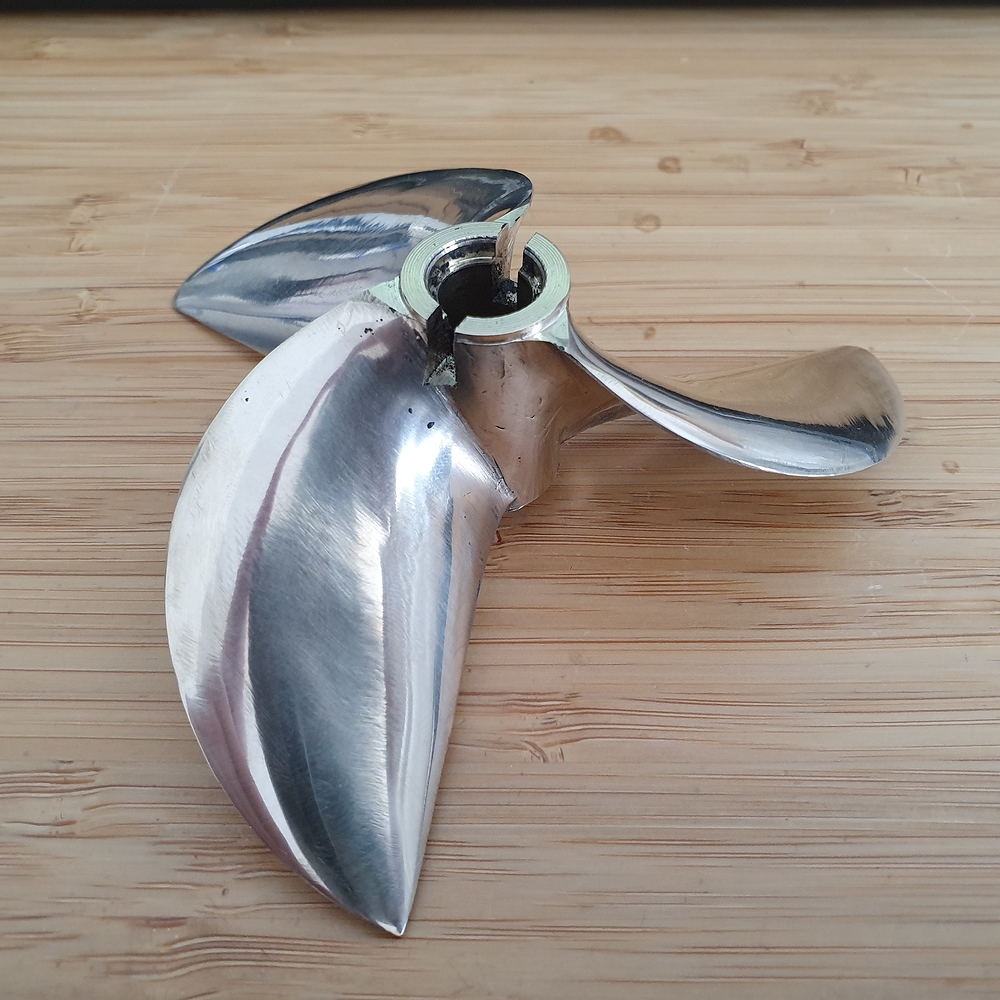
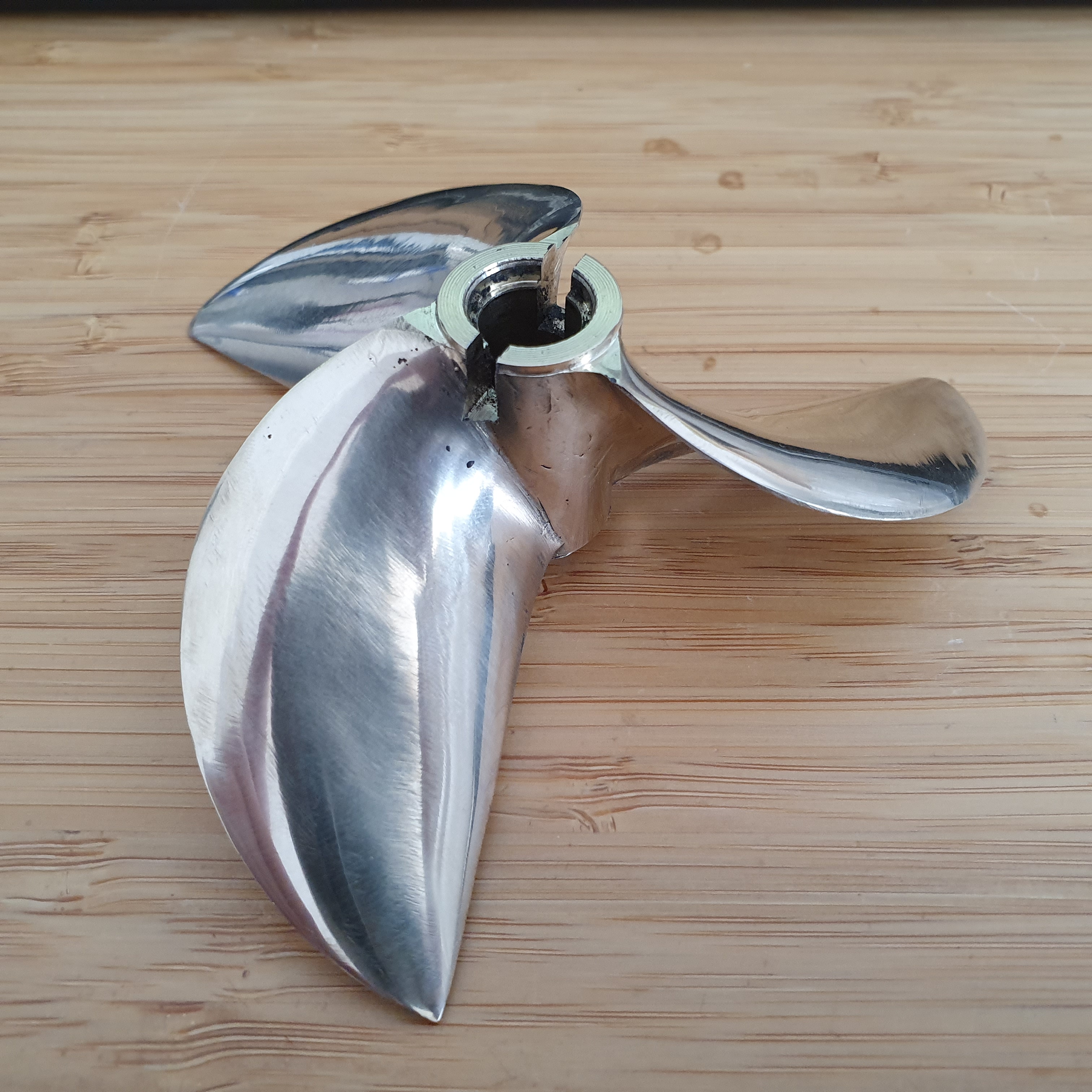
I got that from a prop shop in the UK. Can’t remember the name now.
That’s the place. They make some awesome props.
Ordered one of those cleaver props from prop-shop (CRC/11013/3/LH/BR), thanks for the tip.
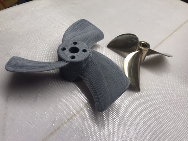
I only have 3d printed ones now so this’ll be my first real prop. Will hopefully arrive next week. will try it out and let you know if it’s any good for my setup.
1 Like
What motor you running? They designed to run between 7500-10000rpm. I know that bazaki on endless sphere managed to get 55kph on a surfboard with one so on an efoil it could be very interesting!
I’ve been too busy with other work over the last 4 months, but got some good stuff coming soon I hope.
I am interested in this also. How to mount? You use Flipsky 100kv? Looking forward to see some assembled pics and logs.
Regards!
80100 setup. Asked them to match it with my 12 mm axle. I have 130kV at 10s so only 5000rpm noload, guessing 4000 loaded…
Planning for 16s for next build so it’ll be a bit snappier then.
Got cleaver prop today, it’s beautiful but really small! I understand the rpm recommendation 
I’ll try it on 10s and see.
2 Likes
This prop might be good to try on SSS56114 360kv direct drive 12S setup, resulting about 15K rpm with this prop (if torque will be enough) .
Check out this guy running high speed kayak on similar setup:

2 Likes