I’m still working on this post but I wanted to post it to save my progress incase something goes wrong. I will remove this message once the post is complete. You are welcome to still post on this thread but I might already answer a bunch of your questions once I finish writing. It might be another day to two… sorry I got a ton of info and want to make sure I do it right
Hi Guys, I have been on this form for a few years now and I finished building my first hydrofoil just over a year ago. I thought I should give something back to the community and show how I made my efoil and explain some of my design decisions. I have only had about a dozen rids on it until my control died a month ago. I’ll be buying a new controller soon and I’m already looking into design my next efoil that will hopefully be air plane save!!! I hope you are ready to read because this is going to be a long ass post with a bunch of pictures. I’ll try to break it down into sections though.
Quick Specs:
- Samsung 40T (version 3) 21700 Cells 4.0Ah 3.6v Nom 168 cells total
- Battery Arrangement: 14s12p
- Battery capacity 48Ah, 2.53 KWh
- Max Battery Voltage 58.8v
- Battery Weight 36.2lbs or 16.45kg
- Discharge Fuse Size 200A
- Charge Fuse Size 40A
- 14s 50A Daly BMS (Charging only)
- Flipsky 65161 120kv Motor
- Standard Flite 3 blade 143mm Propeller
- Flipsky VX3 Remote (Don’t buy it! Soon to be new Volt 4 or Surge/Felix Remote)
- VESC 75/300 from Trampa
- Mast Length 85cm
- Random Chinees Wing 1240cm^2 Front wing area
- Rifle Case Size:
Length: 53.9in or 137cm
Width: 15.5in or 39cm
Length: 5.8in or 150cm - Rifle Case Approximate Volume 79 Liters
- Fully weight of entire board 82.6lbs or 37.5kg : (( heavy boi
- My Weight 165lbs or 75kg
Battery Section:
The Battery was by far the hardest and most time consuming part of this entire build. I did months of research and design work to figure out how to build a safe and efficient battery. Its far from perfect but I will say I think it is one of the safest and sexiest battery’s on the forum.
Why 14s?
I chose to use 14 cells in series for the battery giving me a fully charged voltage of 58.8. I would have loved to go even higher to like 20s since that’s the max the voltage the motor can take and I could have switched from the VESC 75/300 to the VESC 100/250. Higher voltage would allow the motor spin at a higher RPM which could be helpful when your battery starts to run out of juice and the voltage starts to sag. Although with my 14s system low end voltage drop is not too noticeable and the VESC starts limiting power first. Most notably the largest benefit to higher voltage means less current for the same amount of power. Less current means less heat and higher efficiency. You can also start to downsize some components like wire, fuse size, Nickle strip size to safe some weight because everything is seeing less current. Sadly the biggest downside to higher voltage is safety : (. At 20s the voltage can get up to 84 volts and in a wet and salt water environment this can get pretty dangerous. Many major efoil brands and most people on this forum agree that the max save voltage for an efoil is 60 volts or about 14s. So I decided to get the max voltage posable while stay safe and go with a 14s battery. As of right now I would suggest all other builders to go with a 14s battery if using standard lithium ion cells.
Why Samsung 40T?
This battery is made out of 168 Samsung 40T version 3 cells (all new cells on the market should be version 3 since they came out around 2020) I think these are some of the best cells on the market for the price. They are 21700 cells which are a bit bigger then the old standard 18650 cells but they are better in almost every way. I think there is really no reason to be using 18650 cells in 2024. These cells have higher capacity higher discharge current and you need less cells for the equivalent pack size so less labor during assembly. Another contender was of course the Molicel P42A cell which on paper looks better then the 40T in almost every way. However, the spec sheets are not apples to apples and I think the capacity, discharge and live span of the 40T should be similar maybe even better then the P42A. I’m going to do some cycle testing between these cells soon and we will see who the winner is. Also, in the future I might look at making a smaller lighter battery using some more expensive higher capacity cells like the Samsung 50S but we will see.
Samsung 40T Link (They go on sale often I got mine for under $4.00 a cell)
Why 12p?
After choosing a pack voltage and what cell to use I needed to figure out how many cells I want in parallel to determined my pack capacity. The largest driving factor was weight vs ride time. This is my first efoil and I wanted to be able to use it with my friends and have long ride times so I was leaning towards larger capacity. Higher capacity also means the power demand is split up between more cells which should give those cells a longer life. I was also worried about how efficient my first foil would be so I wanted to make sure no matter how bad it is I would still be able to use it for over an hour. At the time of designing the battery one of the largest batteries I knew of were the 2.1KWh ones that Lift and Flite have. I wanted to go a bit bigger then that since I was worried about efficiency so I landed at 2.5KWh which would be 12p. Since then a newer efoil battery has come to the market, the Volt 4 with a 2.5KWh battery with very similar specs to mine. I am pretty happy with my battery the only complaint I have is that it is a bit heavy in the future I might look into making 2 lighter weight batteries that I can swap half way.
Let the battery build begin!!!
Battery Base Plate:
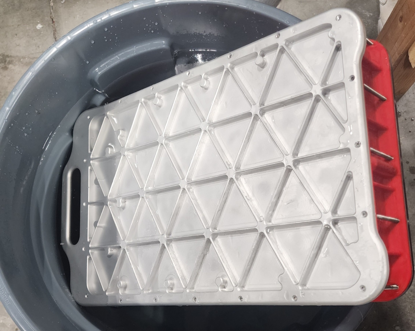
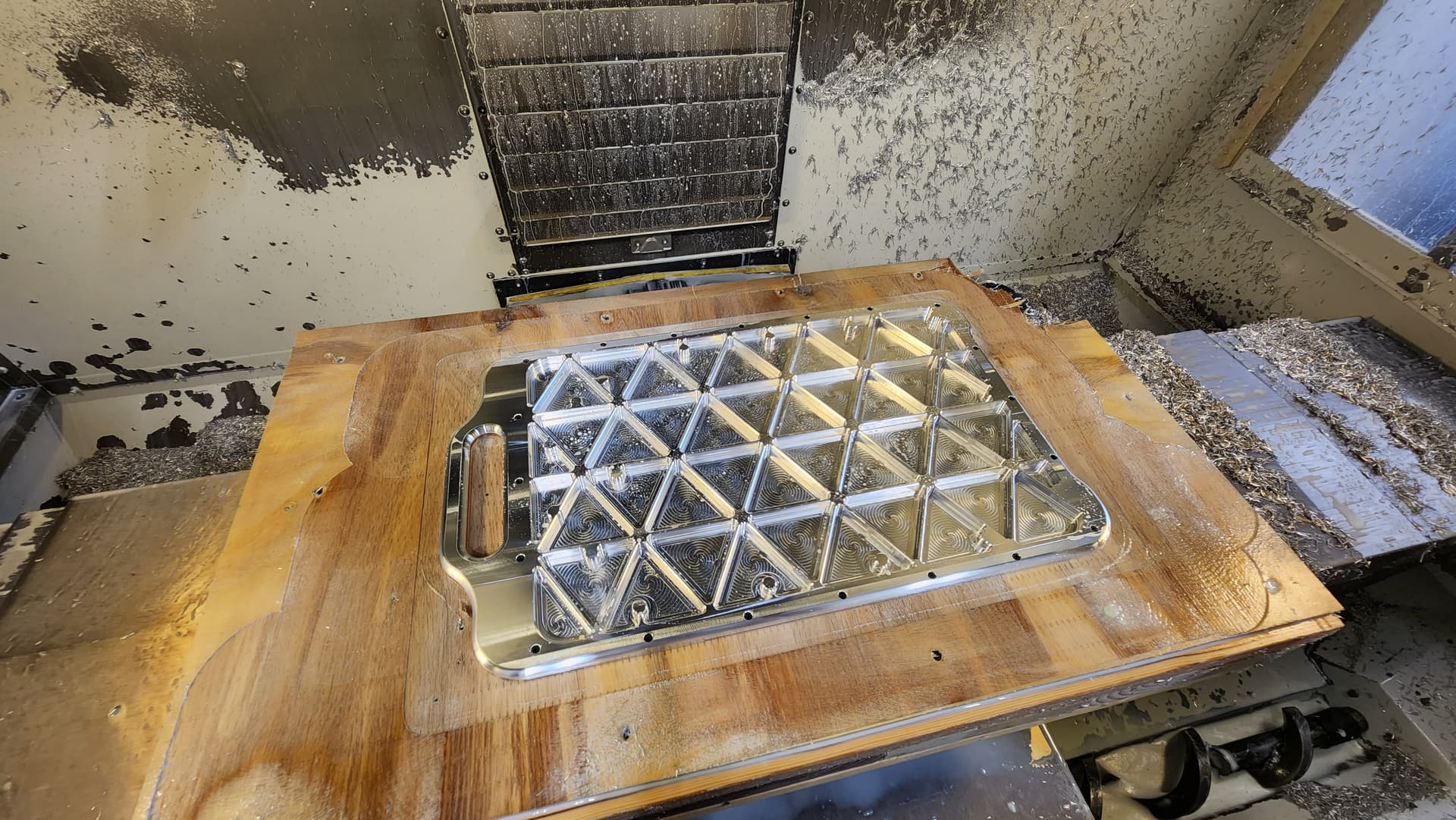
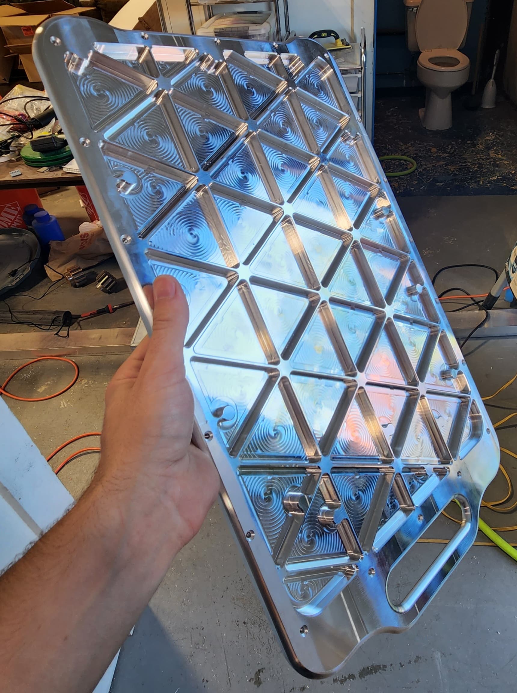
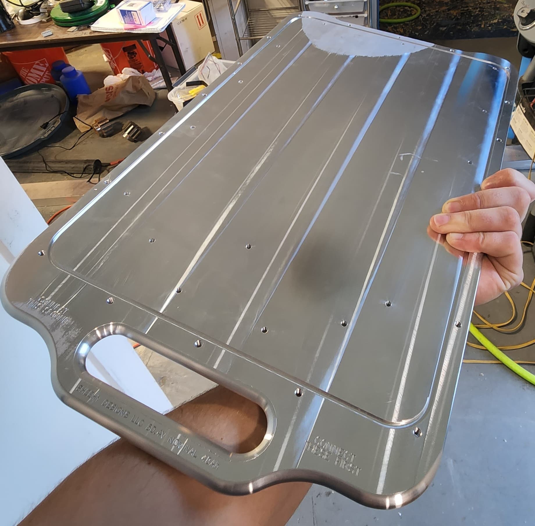
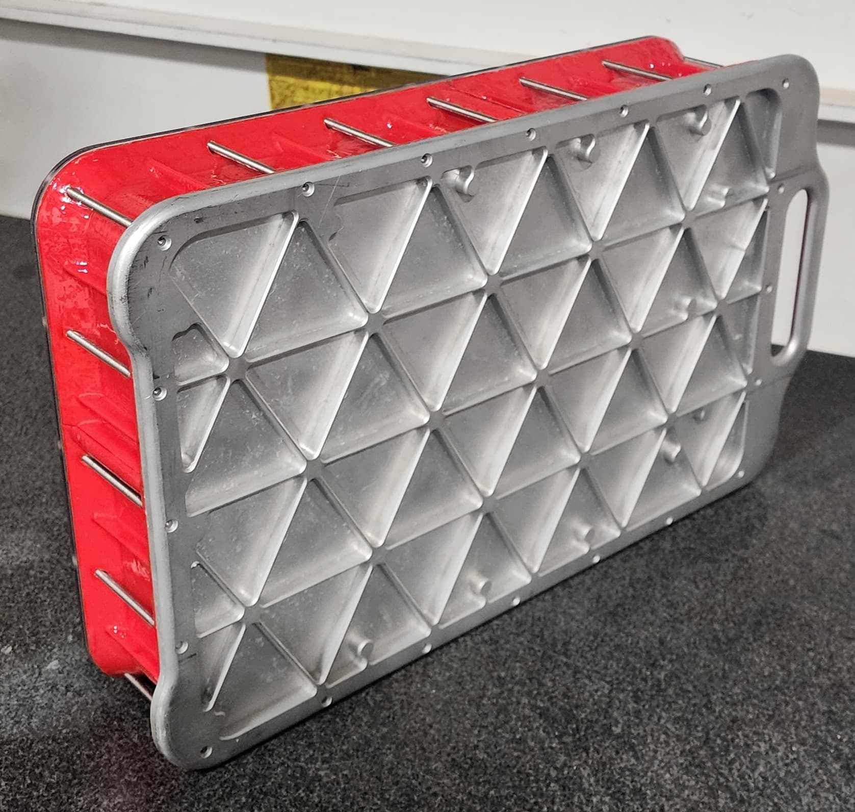
Building the battery started with machining one of the coolest parts I have ever made the battery bottom. I started out with 3/8 aluminum plate stock that weighed over 9 lbs and machined an Iso Grid into it. The Iso Grid allowed me to remove as much material as possible while maintaining some strength and rigidity. It also works as a heat sink to dissipate heat and most impotently I think it looks cool as Hell! After all the subtractive processes I got the weight of the plate down to 3lbs a 66% weight savings. I probably could have gone lighter because it feels rock solid but this was my first ever Iso Grid. For anyone curious the floor thickness of the gird is 0.05", web thickness 0.1" and the unfillet triangle leg length is 2.94". I also bead blasted the finished part to make it look more uniform and so you can read the engraving better.
Cell Holders:
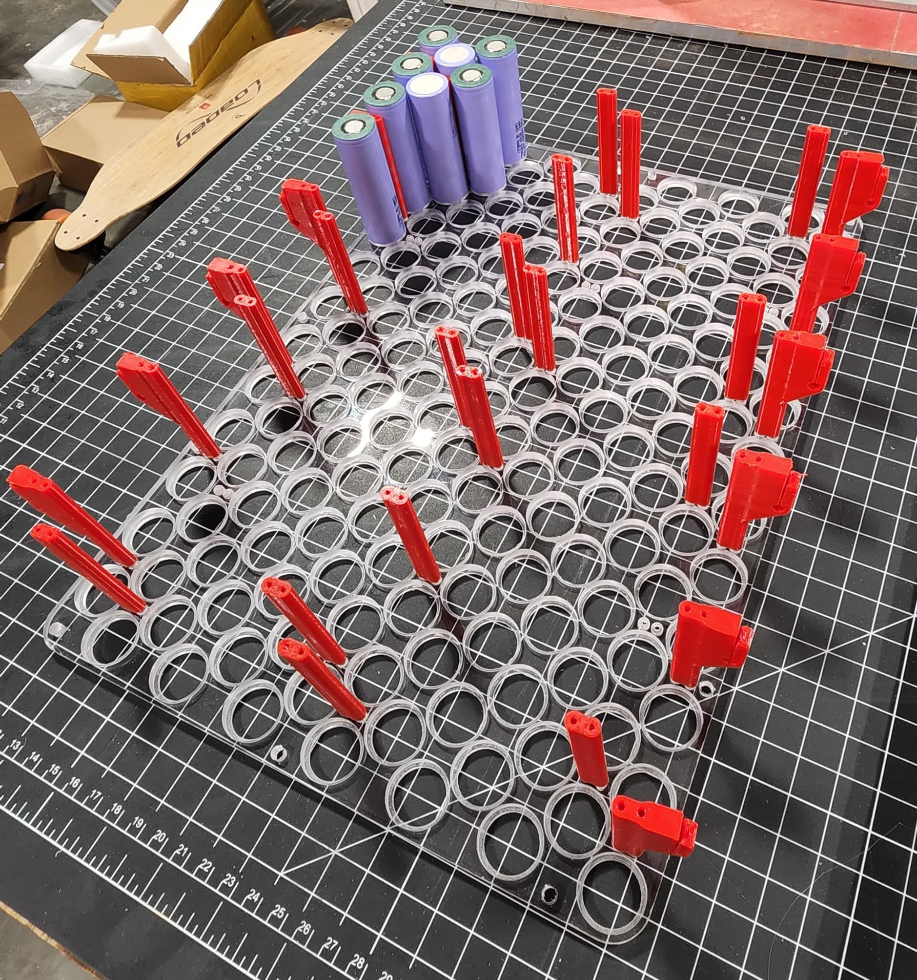
The next step was to make custom cell holders. I was originally going to 3D print them but I was worried about them melting if one of the cells has an issue, causing more shorts and making the problem even worse. Instead I decided to machine them out of polycarbonate sheets. Yes, you can 3D print them out of PC but it would be a bit rough dealing with all the warping also mine are clear which looks cool. PC has a melting point of 300C so it will still melt if something terrible goes wrong but hopefully the aluminum heat sink would take up a lot of the heat and the Nickle strip should hold the cells in place. Another even safer option would be to machine them out of some kind of fiber board like G-10 so they would be super heat resistant but it wouldn’t be clear. These were machined out of 0.25" (0.212" Actual) Polycarbonate sheets with a cell hole diameter of 0.835" or 21.21mm and a depth of 0.173" or 4.39mm leaving a 0.039" or 1.00mm thick flange. There are also mounting holes in the sheet so the two sheets can squeeze the cells together and for attaching the whole cell assembly to the aluminum base plate.
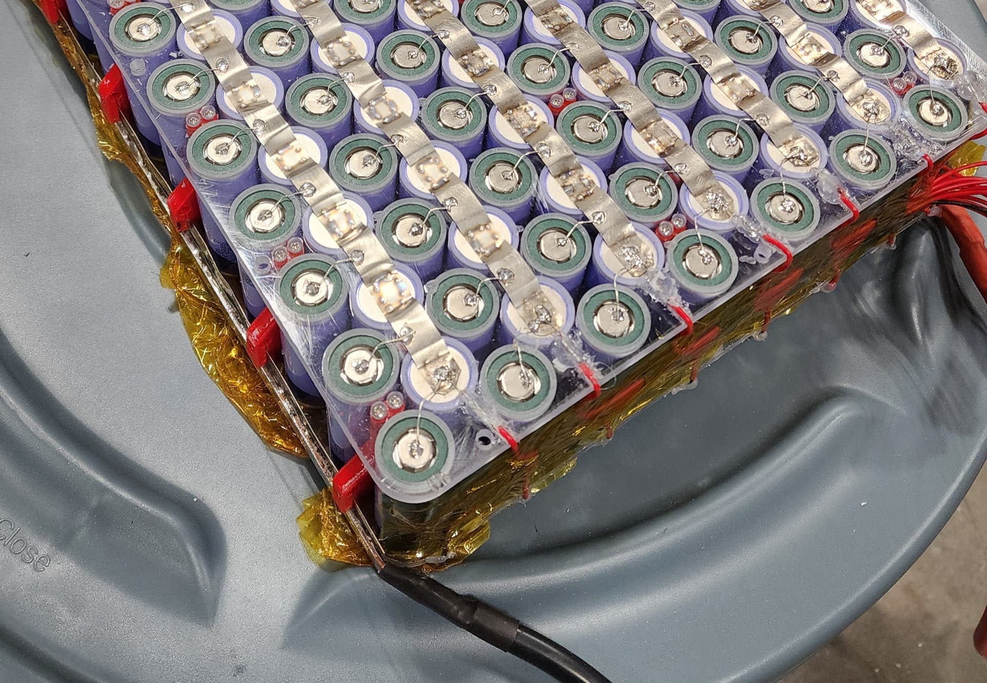
Cell Holder Assembly:
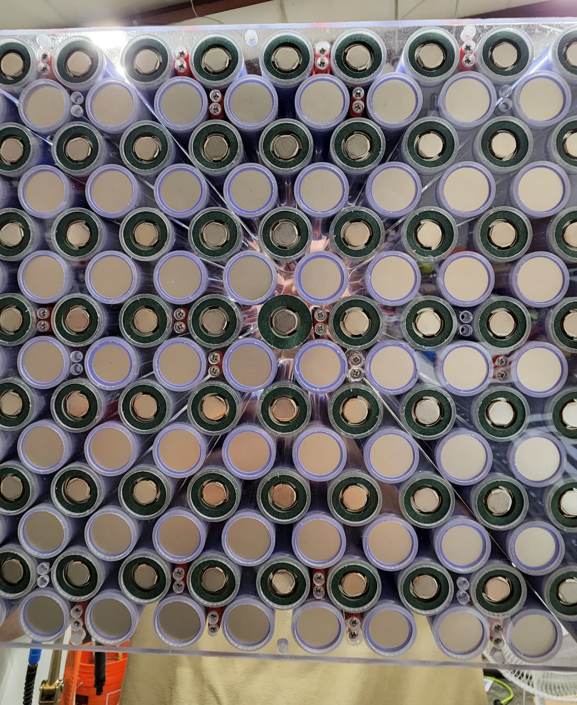
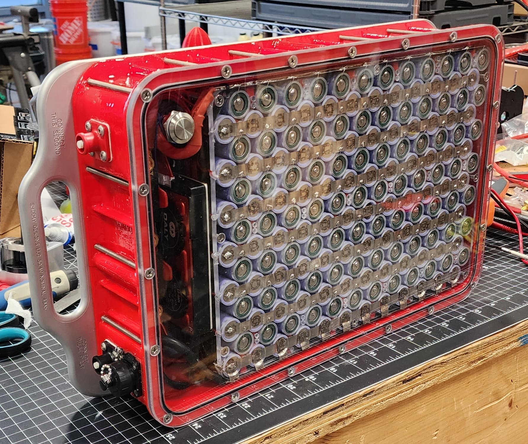
The red 3D printed parts are mostly there to aid in assembly. Once the pack is assembly they will see pretty much no load. They hold the two sheets of acrylic together keeping all the cells in place for welding and wiring. The larger ones on either side also hold the main positive and negative bus bars. You can also see I’m using fish paper rings on each of the positive terminals of the batteries to prevent shoring with the Nickle strips once welded. This is probably totally overkill because the PC cell holders are already doing this but it doesn’t hurt. Once all the cells are installed I snapped the second PC cell holder on top and screwed both halves together. Also I should mention I chose this some what weird spacing of cells to make the battery the right size to fit into the rifle case since it is pretty skinny. That’s why there is so much space between the cells in some spots.
Nickle Strip:
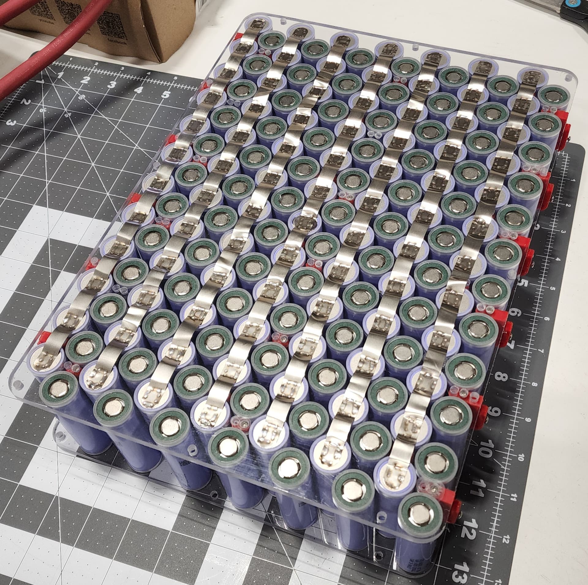
I then convinced my girlfriend to weld all the Nickle strips on the Negative parallel connections of the cells. We tried out best not to weld near the center of the negative cell because I have heard this can damage cell the internals. We used 10 x 0.1mm 100% Nickle strip which should be more then thick enough to handle the amps since the fuses are the bottle neck. Also I find 0.1mm Nickle Strip way easy to spot weld then 0.15mm. With 25 amps while foiling you would only be generating 1.5 watts of waste heat from the Nickle strip if I did my math right.
Why Fuse Cells?
After further convincing I got my girlfriend to solder on all the fuse wire for each of the cells. I decided to fuse each cell to mitigate any issues that could be caused by a defective cell. From my understanding in a prefect world were every cell has no defects, there would be no need for cell fusing. However, although extremely rare you can get a bad cell in your pack. Especially in larger packs like foils with 168 cells or EV’s with thousands of cells that chance gets larger. If a cell does go bad it can cause an internal short which without a fuse will pull a ton of power from all the other cells in parallel adding to more heat and more bad! By having a fuse on each cell, the bad cell’s fuse will blow when it starts pulling tons of power from the other parallel cells. The cell with the issues could still cause a fire on its own but the risk is substantially reduced.
Solder vs Spot Weld Fuses?
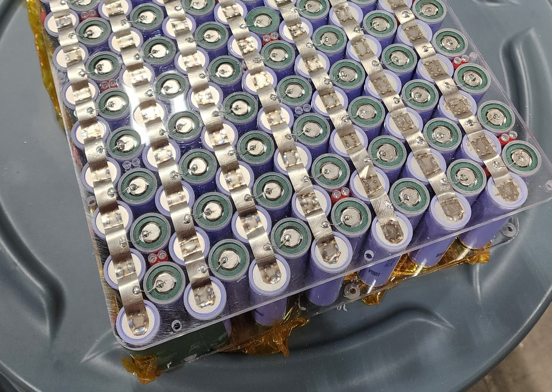
I’m a big fan of spot welding cell to reduce the heat they see during something like soldering. I tried a few time to get my spot welder dialed in enough to spot weld the fuse wire consistently but I couldn’t get constant results that I felt comfortable trusting. If one one these fuse wires did fall off it would be really bad since it would reduce the pack capacity almost 10% and put a ton of strain on the BMS during balancing. It would be possible to fix but it wouldn’t be fun and it might be hard to identify it even happened without watching the BMS data. Since these fuses are critical I decided to go with soldering which should be a bit more robust. After a light sanding and degrease on each cell and Nickle strip and using a high power soldering iron the fuses were soldered. Unlike soldering Nickle strip the fuse wire is quite small and can be soldered in about a second so very little heat is transferred to the cell. Also the cell is being soldered only on the positive terminal for all but a few cells which is far less susceptible to damage from heat. To reduce strain on the fuse wire we made it a little longer then it needed to be which is why each one has a little bend in it.
Sizing Cell Fuse Wire:
Sizing fuse wire can be a little tricky because the thinner the fuse wire the more safe the battery is because it will blow faster. But the thinner the fuse wire the more heat will be generated and the battery pack will become less efficient. I ended up picking 26AWG tinned copper wire. If you check online most sites will give it a failure current of around 20.5 amps. After doing some research I think most of theses sites underestimate the value. I think the 26AWG wire will fail more around 41 amps but I don’t currently have the ability to test it. Since the Samsung 40T Cell has a max rated discharge rate of 35A if its pulling more then that something bad is happening and the fuse should fail. Since this is a 12p pack in order to blow all the fuses you would need 492 amps and at that point the 200 amp battery discharge fuse should blow first. As of right now I have not blown any fuses from normal operation. At a foiling current of 25amps each fuse wire should be only seeing 2.08 amps of current if you multiply this by all 168 connections and a fuse length of 13mm you are only loosing 1.38 watts of heat. I think that extremely low efficiency loss is worth the added safety.
Battery Fuse Wire Link
Main Battery Bus Bars:
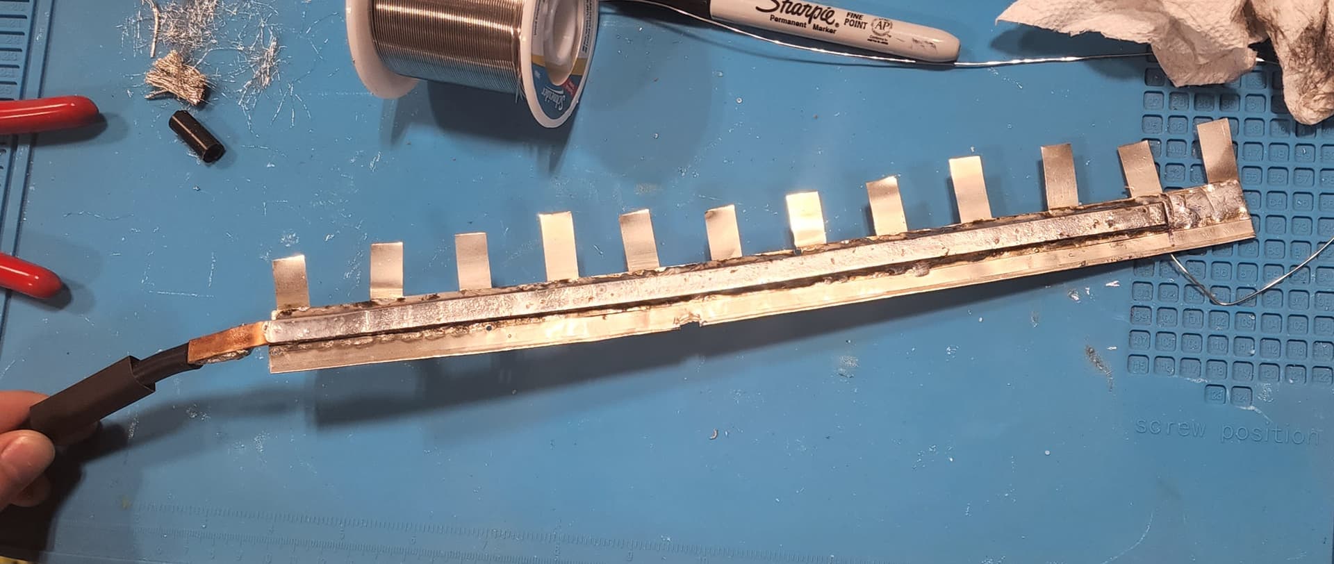
My bus bar solution is a little bit janky because I didn’t have much space to work with. I wanted a bus bar with a pretty thick cross sectional area so I wouldn’t have any efficiency losses. I originally was going to solder a 6AWG wire to Nickle strip but it turned out to be difficult to do and it would take up too much space. Instead I Decided to solder a 8x2mm copper bar to 20x0.1mm Nickle strip. If you count all the solder I used this bus bar would be equivalent to 4AWG wire. I then spot welded welded more taps the the Nickle strip side of the bus bar so they can get bent and welded to the first line of cells. The other bus bar just connect to the first line of cells with the fuse wire. To make the other connections in the battery I soldered on a 6AWG wire to the end of the bus bar. When installed the 3D printed red parts have a screw to clamp onto the Nickle strip part of the bus bar and hold it in place.
BMS Balance Fuses:
To keep my BMS from doing anything stupid and to mitigate the issues from a balance lead shorting out I put a fuse on each one. The Daly BMS 50A version that I picked out can only balance at 35 mA max which means I can get away with a really small fuse wire. I ended up going with the smallest wire I had on hand 30AWG which I predict should fail at 20 amps. I would probably have wanted to go with a smaller fuse then that but soldering wire that small can get hard and fragile. A better option may be to go with something like a 5amp Pico fuse which should have thicker legs for solder and would blow at a lower amperage. I would love to go even lower with a 1amp Pico fuse but the resistance is 0.128 ohms which I thought was a little high but it probably wont effect anything though. I forgot to cut out channels for the balance wires on the bottom side of the battery so I had to use my soldering iron. It looks a little bad but you wont see it when the battery is assembled. Also added a glob of hot glue to ack as a strain relief for the fragile fuse wire.
Balance Fuse Wire Link
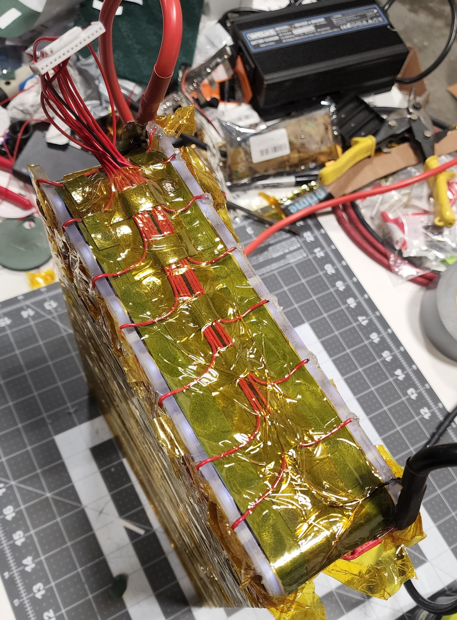
Balance Lead Routing:
One rule I have heard a lot on this forum is only attach your balance leads to the negative side of the cell. This is because the negative terminal of the cell is pretty much the whole body of the cell. Since you usually run the balance leads at least partially along the side of the cell it will reduce the chance of a short if the insulation wares through. I also made sure to put fish paper between the cells and the balance leads to again reduce the chance of shorts due to fraying insulation. Lastly I made sure to not let any of the balance leads cross when they are Kapon taped to the side of the battery to again stop any shorts from forming. The loose Kapton tap on the top and bottom of the cell pack is just to prevent shorts while its being made it will be removed once the pack is about to be assembled.
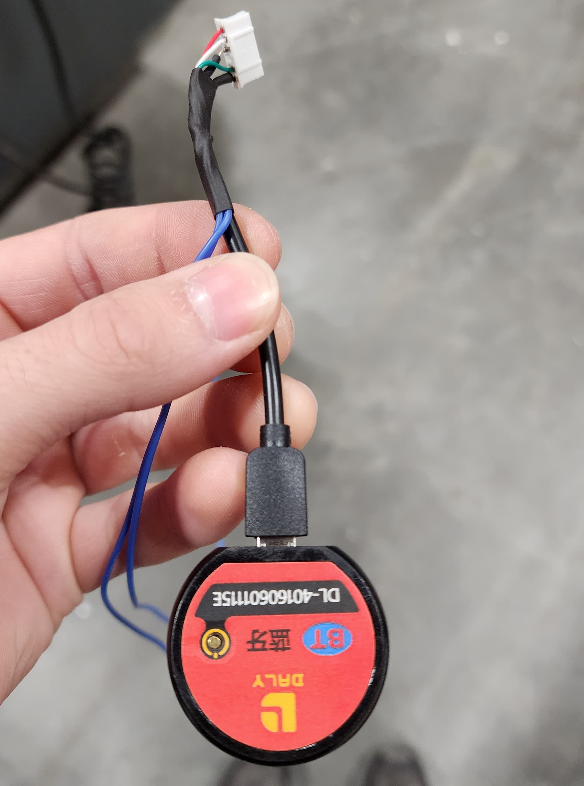
BMS:
Weather or not to use a BMS is a topic I have seen countless times on the forum. I am very much pro discharge only BMS. Not having to deal with balance leads when charging you battery is so nice. Also the less water ingress points you have in your battery the better. My battery only has 2 main discharge ports and a multi poupous 2 conductor charge port that is also used as an anti spark port. The biggest argument I hear for not having a BMS is that you are trusting a cheap Chinese electronic to keep you battery safe and not burning down your house. This is a very fair point but I have a few methods to mitigate this risk. I think your BMS is most likely to fail during charging. I only change the battery in a safe area under supervision. The battery is trusting the BMS the most during charging since its the one telling the power supply when to stop the charge. If you significantly overcharge your cells they will catch on fire. I never leave my battery at a state of charge over 50% for more then a few hours. This will reduce the amount of energy in the battery during storage so that if the BMS does act up it will have less energy to play with. Also this is a good state of charge to keep your batteries healthy for storage. Every time end a ride with my efoil or finish charging the battery I check the voltage of the 14 parallel cell packs to make sure they are all balanced and at a healthy voltage. I picked a Daly 50A BMS which is a some what repeatable brand of BMS and it comes with a Bluetooth module which makes checking on the battery and changing values easy. Most importantly I fused all the balance leads from the battery to the BMS so if it does do something stupid they will blow. I’d like to think these risk mitigation tactics will help to keep my battery safe while making it easy to use. I would have loved to use a Discharge BMS, I even bought one but they are just so big. If you battery is made well and you are using all new cells the battery should discharge evenly and the VESC should know when to shut the power off before the voltage gets too low.
14s 50A Daly BMS Link
My Next BMS:
For my next pack I’m thinking of using the the Trampa VESC BMS which is a charge only BMS but it can communicate through CAN to the VESC and tell it to shut off if it thinks something is wrong. Its also super small, light weight and made buy a super reputable brand. Just wish it was a little cheaper and could charge with more then 12 amps.
Trampa VESC BMS Link
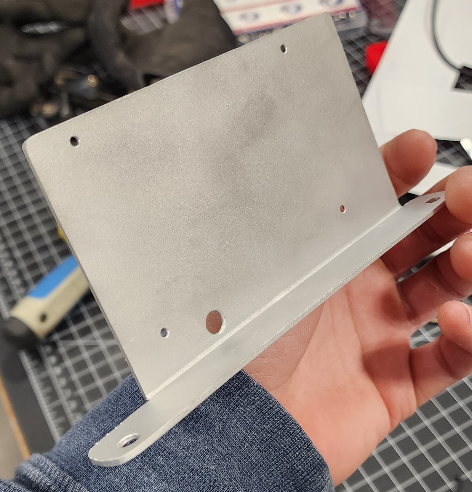
BMS Mount:
I made a sheet metal mount for the BMS out of aluminum to hold it in place and to transfer heat from the BMS during charging to the main aluminum base plate. I made sur to use thermal paste between the BMS and the Mount and between the mount and the battery base plate. I also put some Kapton tape on the back of the mount that will face the battery to mitigate any potential shorting. The larger hole on the mount is to pass through the temperature sensor on the BMS if your are curious.
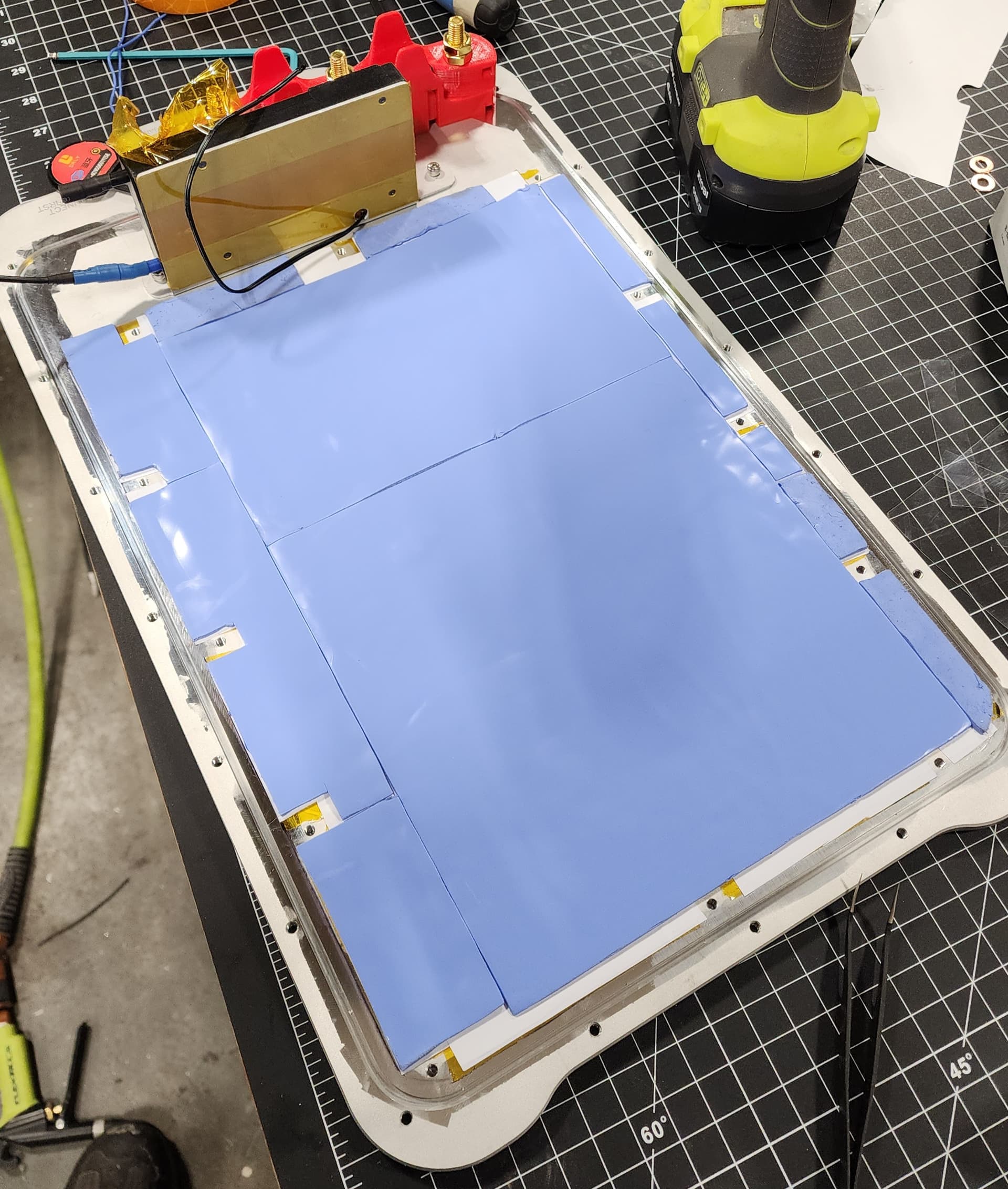
Cell Cooling:
One of the best ways to keep your battery healthy is to make sure it is at a good temperature when discharging and charging. To help with this I wanted to make sure the cells had good contact with the aluminum base plate but they also can’t touch it directly because they will obviously short out. The bottom part of the battery has a lot of uneven surfaces from the Nickle strips and fuses so I decided to use 2mm Silicone Thermal Pads to fill some of this gap. These conduct heat fairly well but they are really fragile and I was worried about the sharp Nickle strips eventually digging there way through to the aluminum and causing shorts. To mitigate this I used some Permanent Adhesive Vinyl that I stuck down before the thermal pads.
The Vinyl is only 0.004" thick so it should have pretty good heat transfer and despite its thin size it was vary abrasion resistant. The vinyl is the white stuff that you can see sticking out around the thermal pats in some spots. Make sure you peel off the backing on the thermal pad before installation we almost forgot. I will say this was almost certainly complete overkill for my size battery. With so many cell not even close to there peak discharge rating the pack barely gets warm. I did want to test some of these methods though because I will probably build some smaller packs soon that will produce a lot more heat.
2mm Thermal Pad Link
Adhesive Vinyl Link
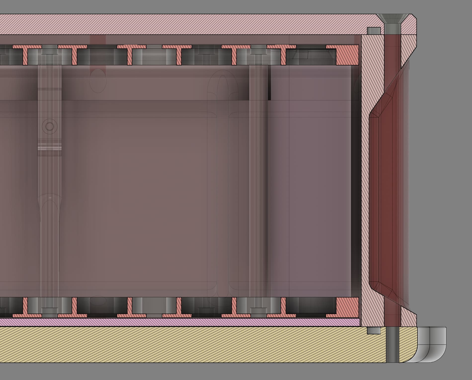
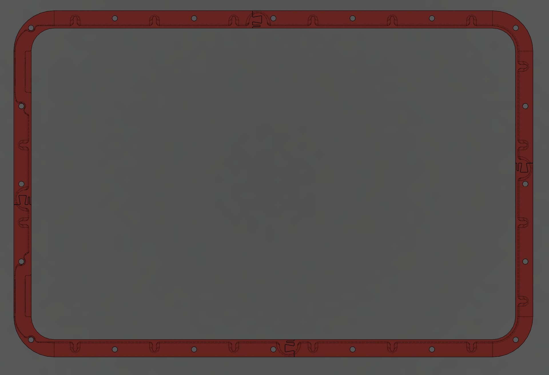
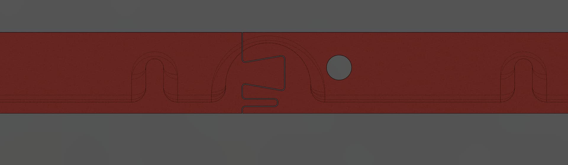
Battery Side Walls:
I took me a while to figure out how I wanted to build the side walls of my battery pack. I would have loved to machine them out of aluminum but that would be an expensive piece of stock and even after turning it into swiss cheese it will still be pretty heavy. The best choice would probably be to make it out of glass or carbon fiber but I lack those skills especially for a relatively complex shape like this involving O-ring seals and thin walls. I will probably look at this option more closely for my next battery though. Since I was out of options I decided to 3D print the side walls. I designed the part to keep 3D printing in mind so a lot of the weird angles are to avoid using support material. Also there needs to be large flanges on the top and bottom to make room for the O-ring seals and screws. I wanted to make this part as light as possible so I used very thin walls where I could (0.08") and added some ribs for strength. The largest printer I have that I can trust to print with decent quality is a Prusa MK3s so in order to fit I needed to break the part up into 4 pieces. To make the glue joints stronger I designed a weird joint to allow for more surface area. The parts were not printed solid to save weight. The wall thickness of the print was about 0.04" so that the thinnest portion of the walls were solid. Also PETG was used for almost every printed part in the project. Its prints pretty easy and has higher heat and impact resistance then PLA. Also the O-ring groves and bolt spacing were calculated to make the correct gland squeeze and fill. I could have gotten away with a lot less screws if the PC top plate was stiffer.
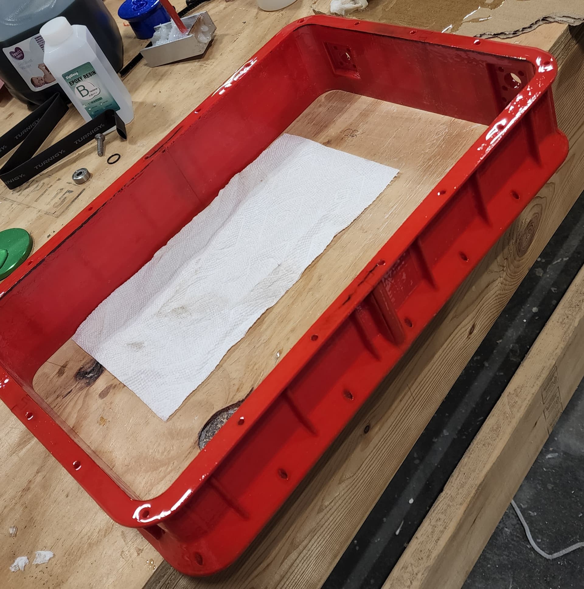
3D print sealing:
Since its pretty hard to get water tight prints right off the printer I needed to seal the battery side wall. PETG can be a little hard to bond to for some epoxies so I decided to go with one that is designed for 3D printing XTC-3D. I convinced my girlfriend to degrease and then put multiple coats of epoxy over every surface of the print including the thru holes. The thru holes were especially hard to coat so in a future design I would have probably made them open ended slots. The O-ring surfaces were coated with an extra thick layer of epoxy because during 3D printed the base warped a bit at the edges. XTC-3D was also used to glue the 4 parts together.
XTC-3D Link
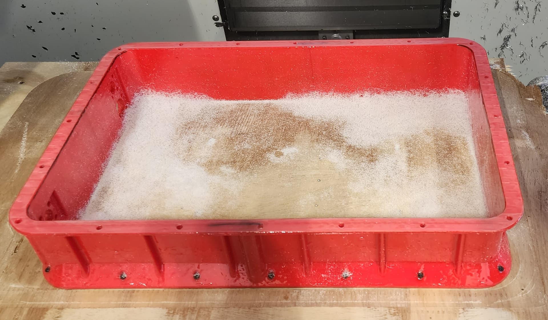
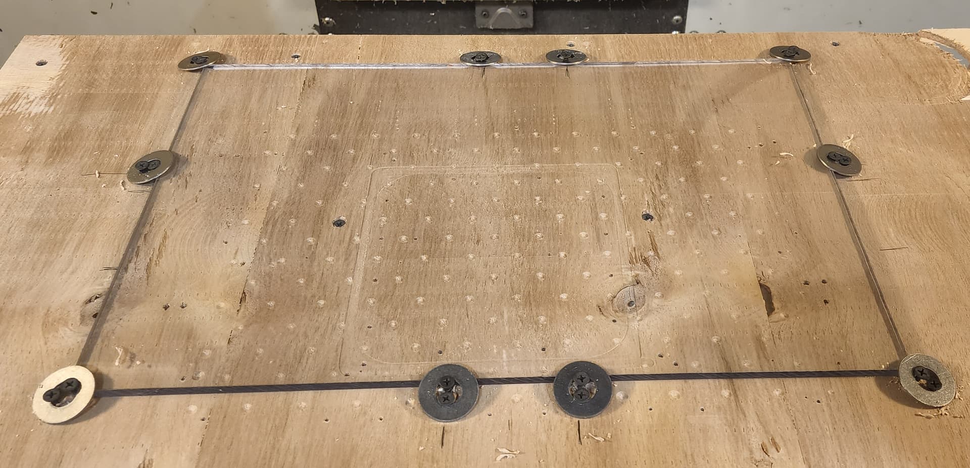
O-ring Surfaces:
For good sealing it was critical to get the O-ring surfaces fairly flat. We originally tried using sand paper on a piece of aluminum plate but after a few hours or sanding and recoating with epoxy we gave up. I ended up having to machine them flat in the Haas which still took a couple tries because of uneven coating of the epoxy. This process was probably the most time consuming and frustrated part of the whole efoil build. I the end we were able to get them very flat without any uncoated plastic showing through.
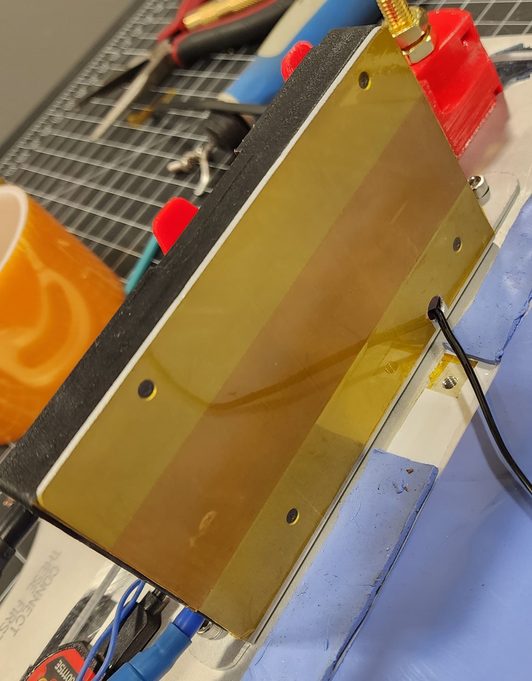
Battery Top Plate:
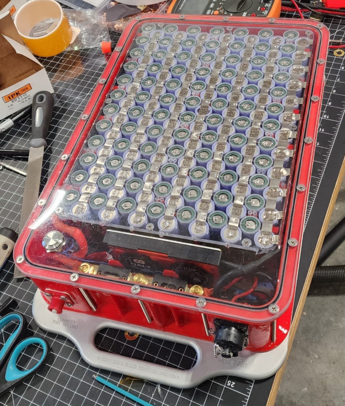
For the top plate of the battery I decided use a machined piece of PC. This part was pretty easy to make since it only needed an O-ring groove, mounting holes and the wake up button for the BMS Bluetooth. I wanted this piece to be clear so I could check for any water ingress, blown fuses and the battery just looks so cool so I wanted to be able to see in.
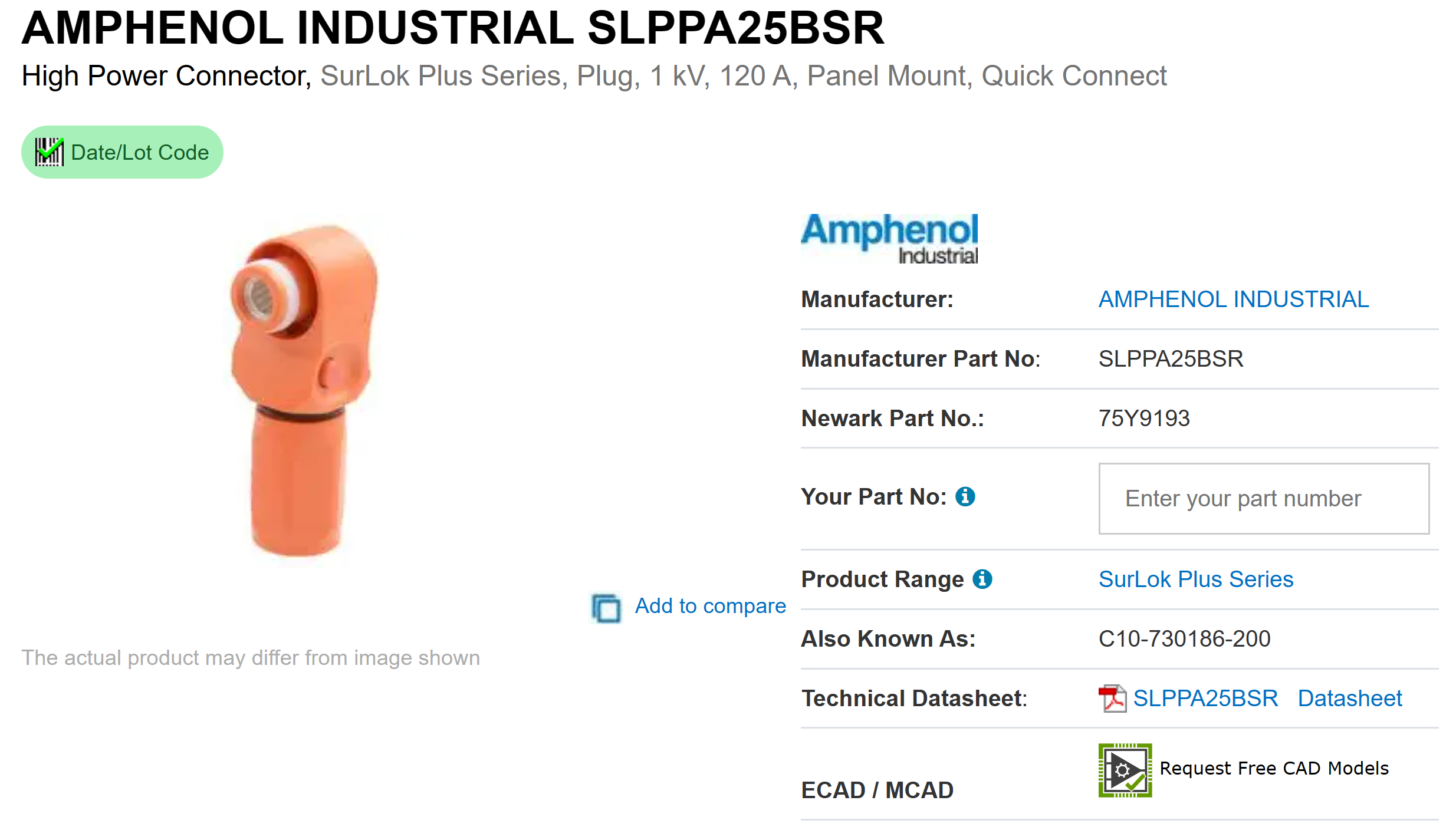
Battery Connectors:
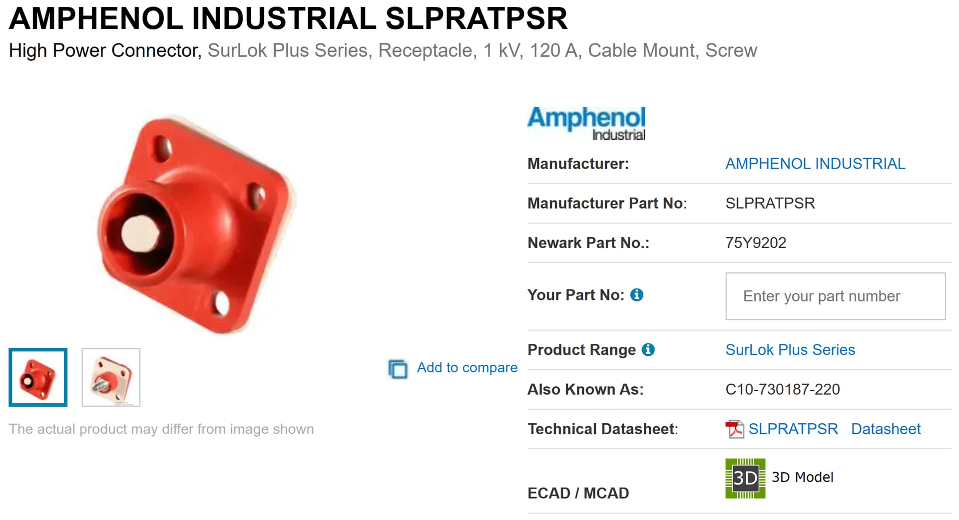
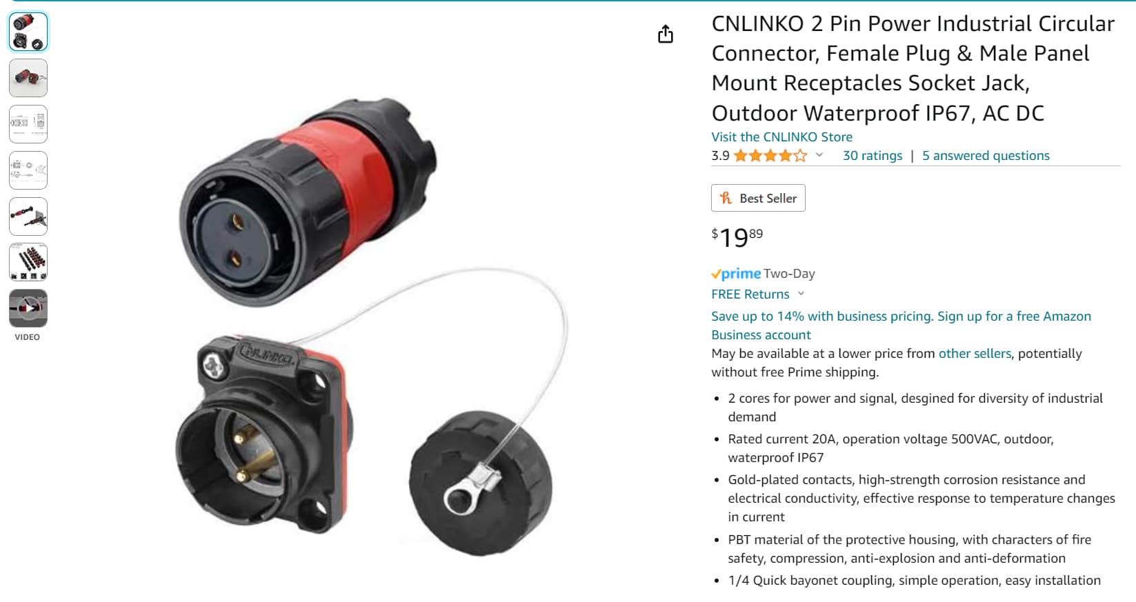
Connectors were also something this forum helped me with a lot. The best connectors I found for the main discharge leads were the Amphenol Industrial ShrLok Plus connector. They are rated for 120A continuous which seems a little low but I’m sure they can do a lot more then that for short periods. I’m also pretty sure they are the same connectors Flite uses on there batteries. They are IP67 rated thanks to the little gasket on the wire side connector and they lock together with a little push button on the side of the connector. There is another connector out there that looks similar to this one but it uses a little fish hook thing to lock together instead of the push button. These are not rated for many mating cycles so I would not buy them. For the Charge/Anti spark connector I used a half turn two conductor waterproof connector I found on amazon. It works well but I don’t think its the most waterproof. All the connector body’s that mount to the battery came with a rubber gasket but none of the screws had seals on them so I used some marine silicone sealant under the bolt heads and nuts to make sure they stay waterproof.
Discharge Connector Red Wire Side Link
Discharge Connector Black Wire Side Link (The Site Picture Color is Wrong)
Discharge Connector Red Battery Side Link
Discharge Connector Black Battery Side Link
Charge and Anti Spark Connector Link
Marine Silicone Sealant Link
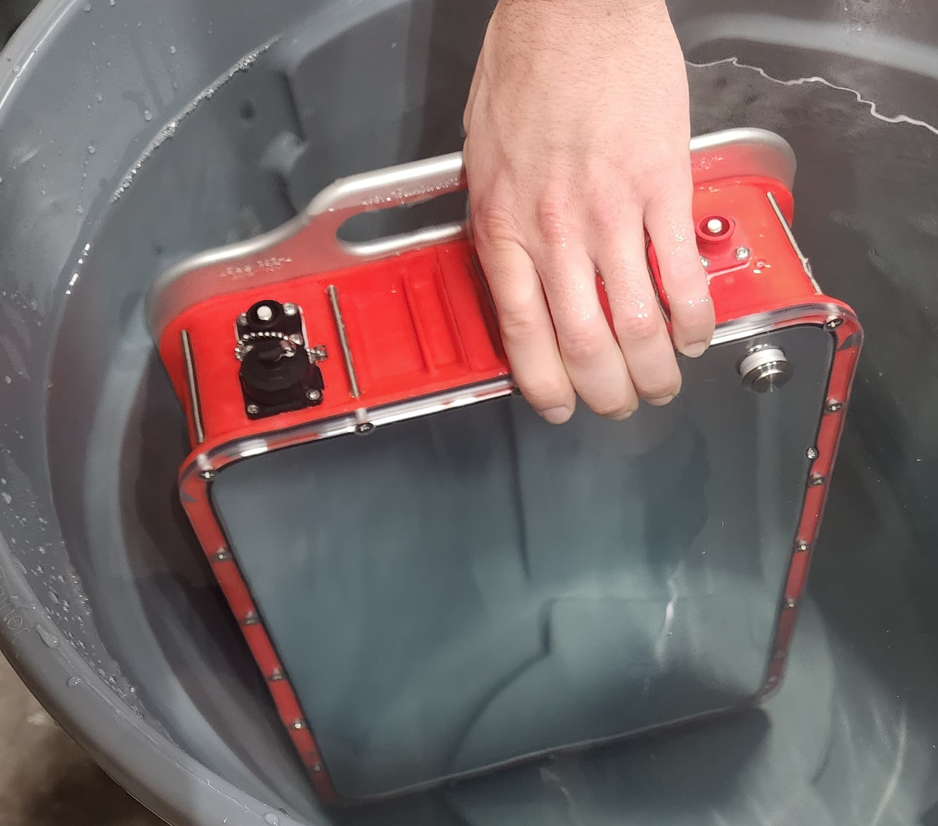
Hydro Testing:
Since its pretty critical to make sure my battery stays dry I wanted to test the housing before I put the whole cell assembly inside. I filled up a big trashcan with water and held the housing at the bottom for a few minutes and not a single drop of water came in. Even the push button switch didn’t let any through. I wish I could have tested it at the bottom of a pool but it was winter and at that depth it might have imploded haha. I stand by this water proofing technique because the first 3 times I used my foil the rife case almost completely filled up with salt water and my battery was submerged in it for almost and hour and not even any humidity got in.
Bluetooth Push Button Link
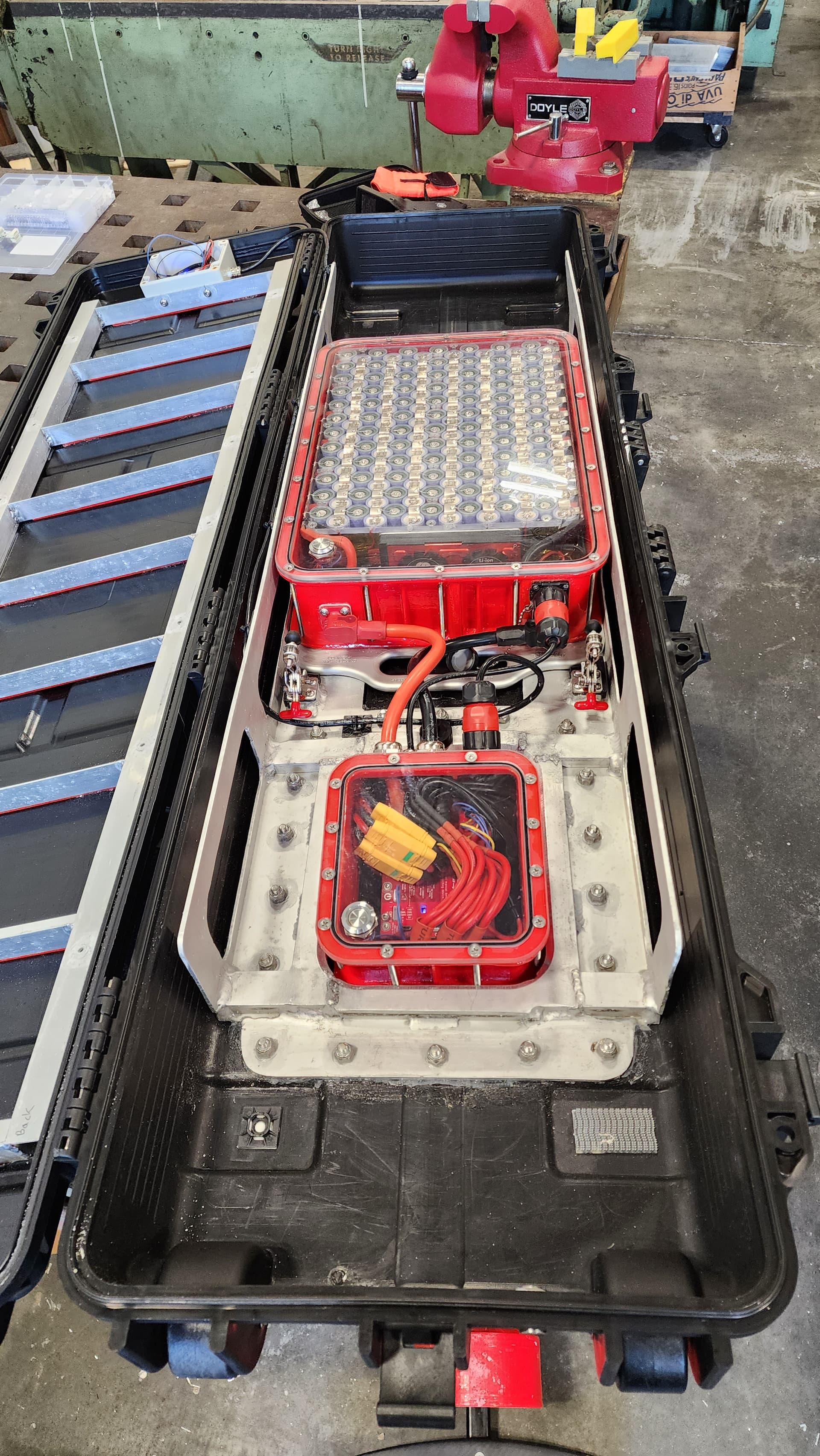
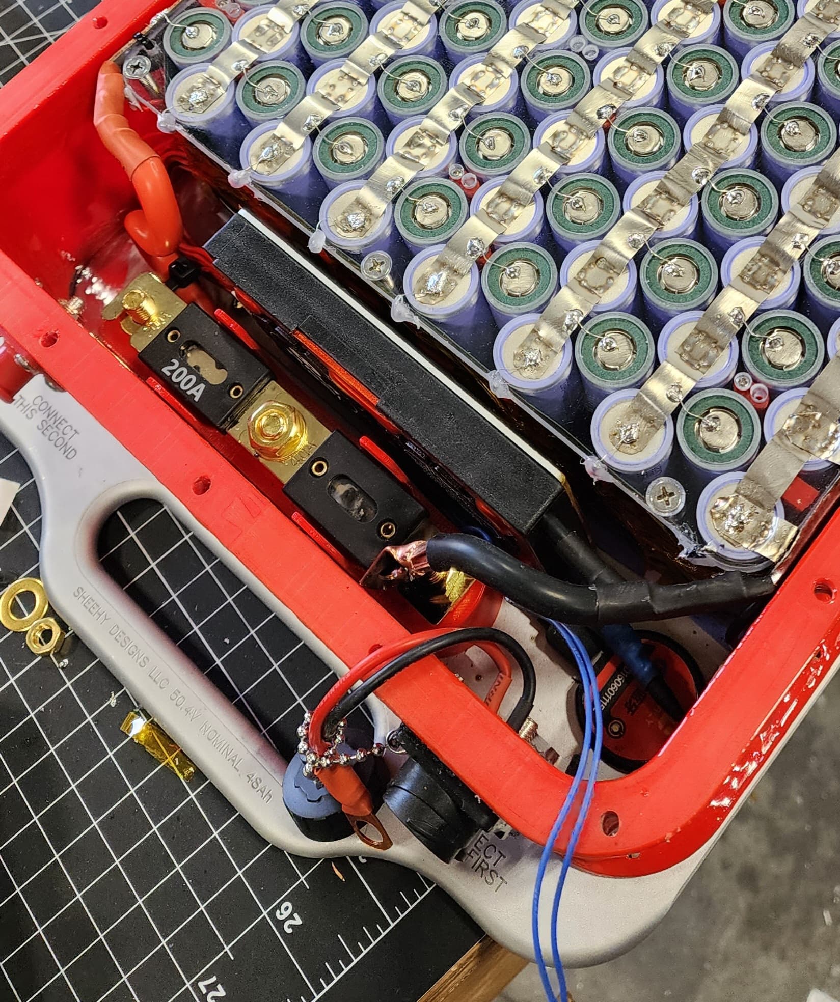
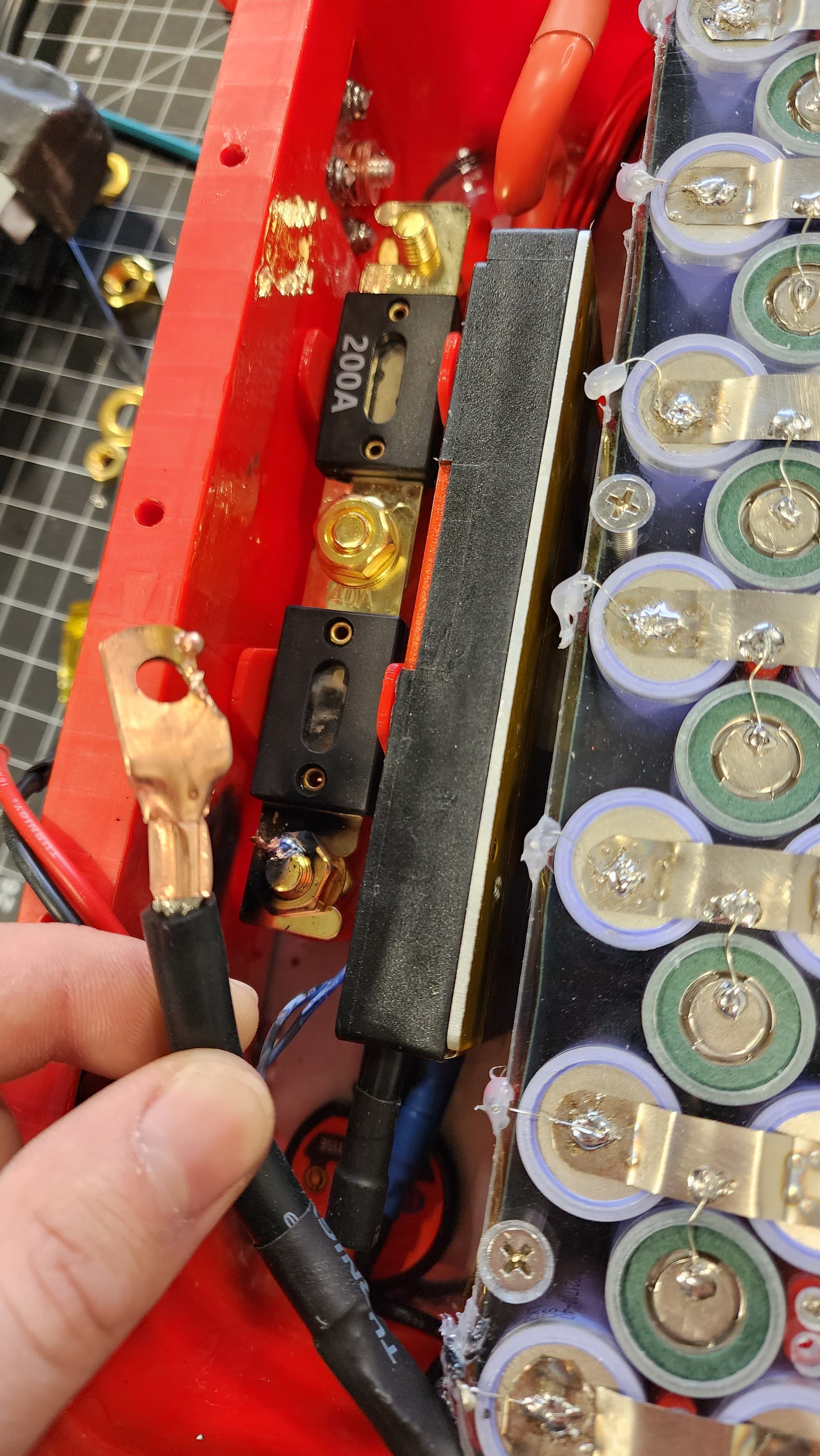
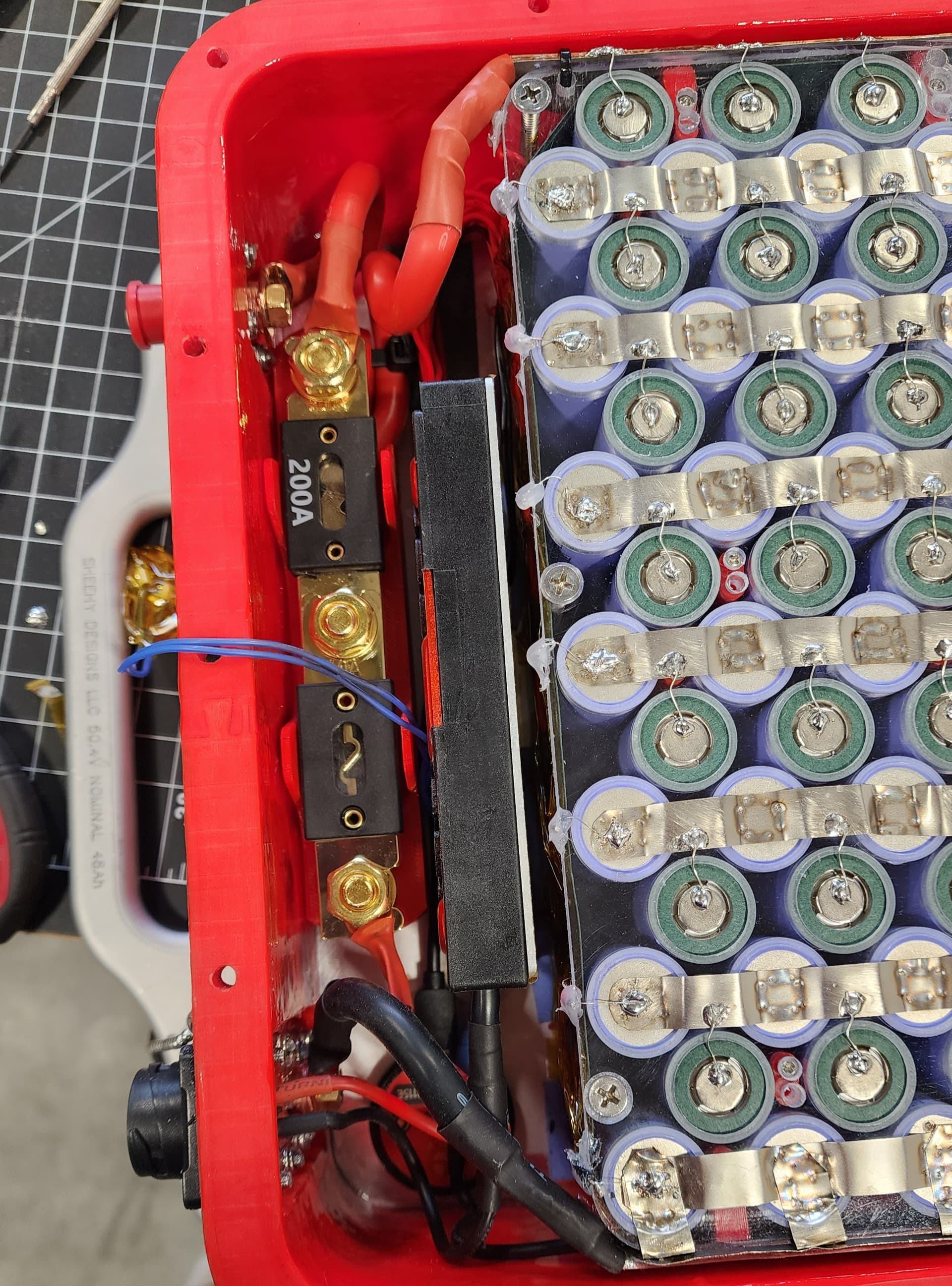
Final Battery Assembly:
The cell assembly was placed on top of the thermal pads and screwed down with 8 long #8 screws to hold it to the aluminum base plate. To protect agents shorts on the main discharge and charge connectors I added fuses on both. I used a 200A fuse on the discharge and a 40A fuse on the charge side. I 3D printed a custom fuse holder to save space and help with wire routing. I used VHB tape to hold down the BMS Bluetooth module. The Bluetooth module turns off after a little bit if the battery is not being charged or discharged but there is a button on the module for waking it up. Since there is no way to access this button when the battery is sealed I spliced into the Bluetooth connector so I could use an external button. The thin blue wires go to the external button that I mounted on the PC top plate. All the high power wiring in the battery is 6AWG. The BMS temperature sensor was routed around the left side of the battery till about halfway down and it is Kapton taped in place. I would have loved to get this into the center of the battery for battery readings but it wasn’t really practical. Don’t forget to test the voltage of your BMS balance connector before you plug it in!
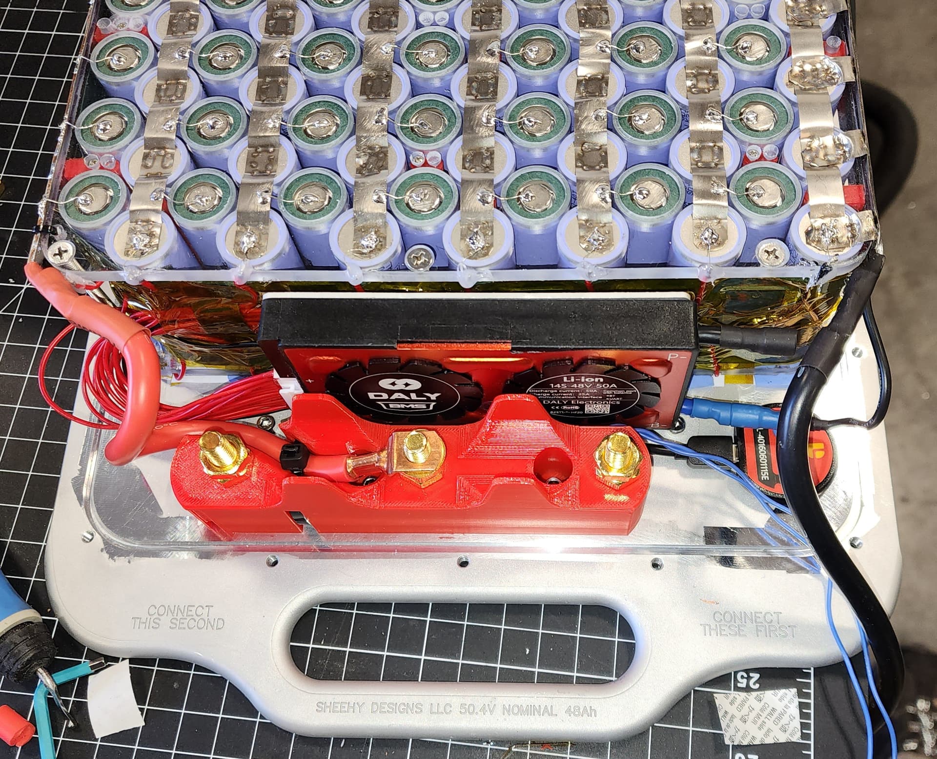
Wiring Mishap!!!
It is a little difficult to get the thick 6awg discharge wirers attached to the studs of the ShrLok connectors. When I went to attach the negative cable I accidently touched the positive battery charge fuse this shorted out the battery!!! Luckily the 40 amp fuse blew instantly and saved me from possibly blowing a ton of the individual cell fuses. To stop this from happening in the future I would probably suggest putting the fuses in last. It did make for some cool pictures though because the wire lug welded its self to the fuse stud and evaporated a bunch of metal hence the black scar on the wall. This was an easy fix and I was able to replace the fuse and lug.
The Battery is Finally Done:
After installing some cut to length O-rings and screwing in all 20 #8 Compression screws the toughest component of the efoil was complete. Here are some finished shots.
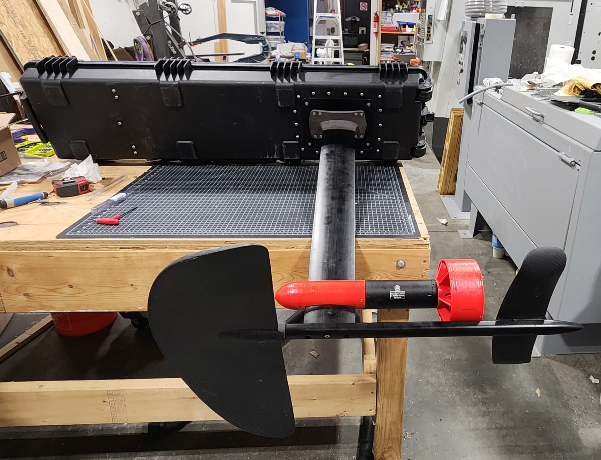
ESC, Mast, Motor, Wings Section: up next stay tuned…