I think that with a component like this it is not possible because at the moment of contact the current is beastly. I have the BMS only for charging, not for discharging
These anti-spark switches that you linked are rated for a maximum continuous current of 100A, which is the only limitation in this context.
They are designed to limit the inrush current when powering on the system, regardless of the battery you’re using. At least that is how they are supposed to work.
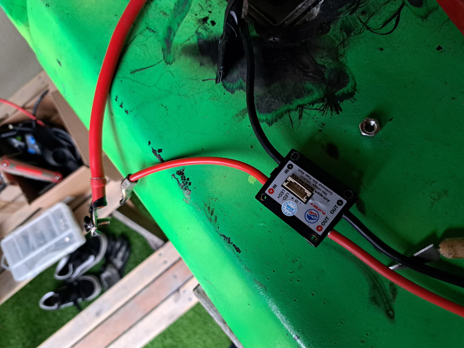
Hello again. I have a DIY Foil assist with a 12S3P battery. Between the battery and the VESC I have an anti-spark switch. When I enter the water, I enter with everything turned off, and when I am in a little deep water (1.5 meters) in the Battery + VESC box I have an external IP69 switch to close the circuit and start the equipment working.
I want to do something exactly the same but with an efoil. The battery is 12S12P and I had put a mechanical switch that I think met the voltage and power requirements, but it burned out in a matter of seconds.
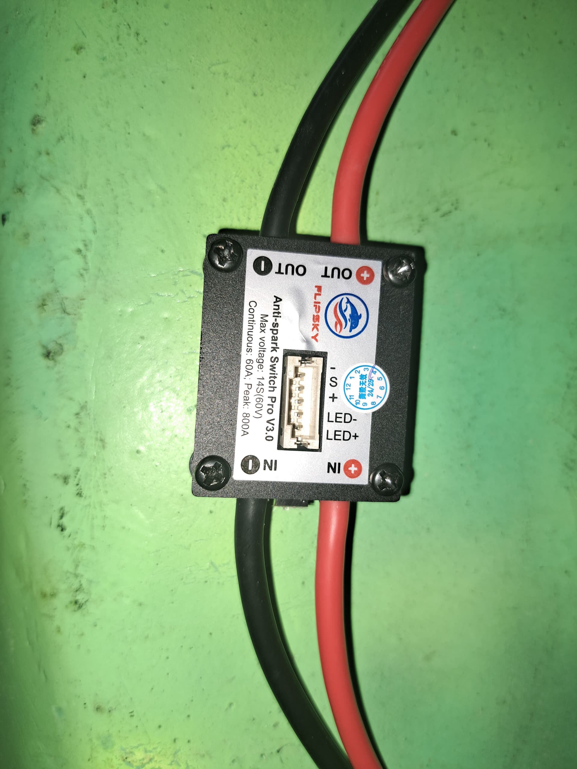
Now I have a flipsky 200A 14S anti-spark switch. This anti-spark switch has 12 awg wires, and my battery is 6 awg.
My fear is if this is going to explode? 12P with the mechanical switch were more than 300A instantaneous. With this switch…will I burn it immediately? I’m a little lost.
I think what you want is some kind of pre-charge circuit. You can try searching the forum for more details. I’ve never made one myself and don’t have any specific to share, but I know there are builds that have incorporated one.
Maybe if you can find some kind of two stage switch (or 3 stage?) like the one you had above where you turn to a first position that connects the pre charge path. Basically battery to vesc through a resister of appropriate size, hold there for some number of seconds (inrush current, but much lower), then turn to the final switch position that just connects the battery normally. Of course this would not be foolproof, but it would be simple.
I make the battery connection on shore, enter the water and then power on remote to go. When I finish I power off remote, carry board to land and after things dry off I disconnect the battery.
The problem is that no matter how I make the connection, it ends up causing a semi-explosion. These last few months I have changed everything and I prefer to leave the surlocks connected and make the connection through antisaprk switch. The truth is that I only have to do what you tell me but it was my last intention, I know that I am going to burn the surlock. I must have some battery problem.
The problem is that no matter how I make the connection, it ends up causing a semi-explosion. These last few months I have changed everything and I prefer to leave the surlocks connected and make the connection through antisaprk switch. The truth is that I only have to do what you tell me but it was my last intention, I know that I am going to burn the surlock. I must have some battery problem.
I don’t know…
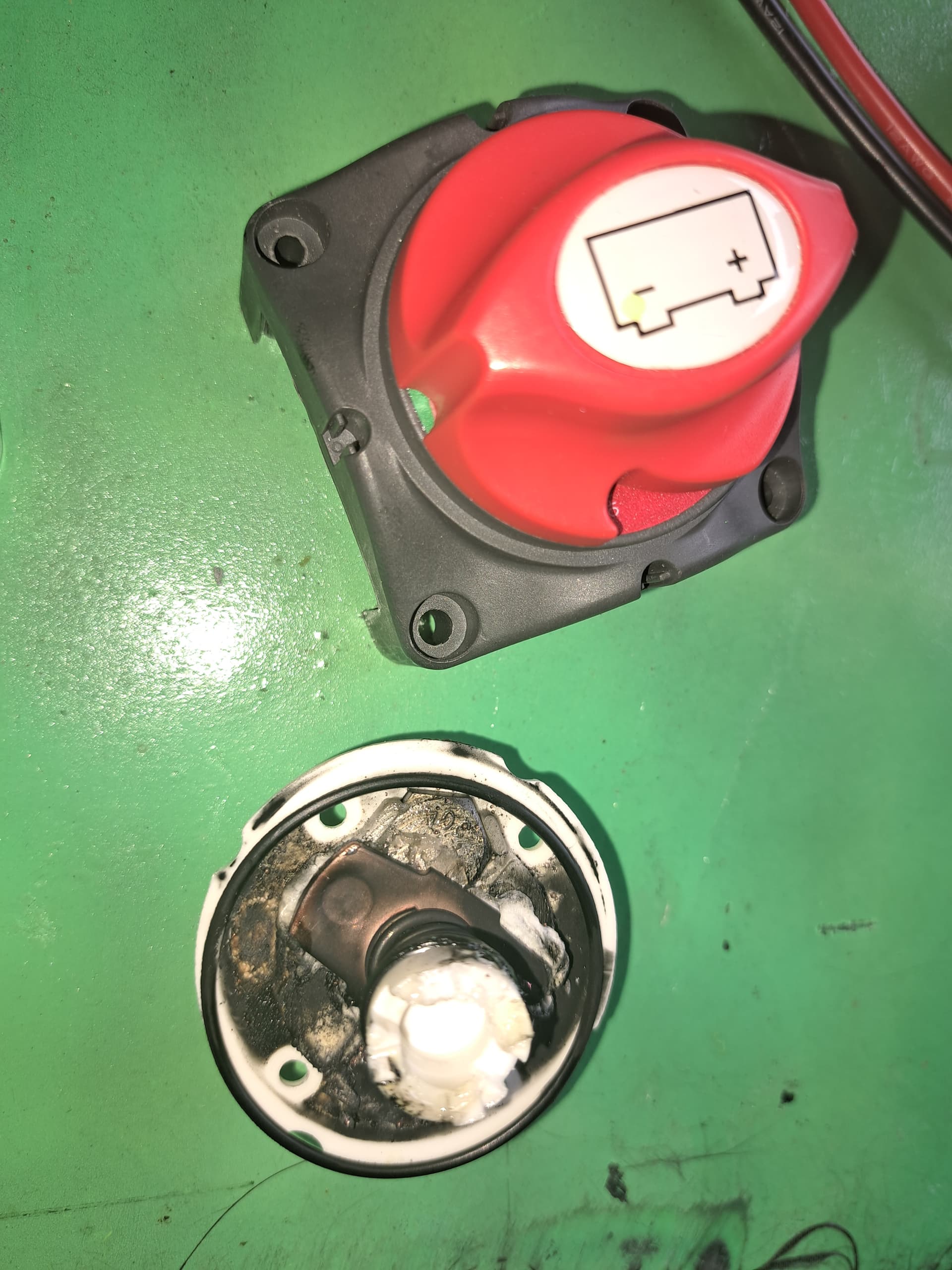
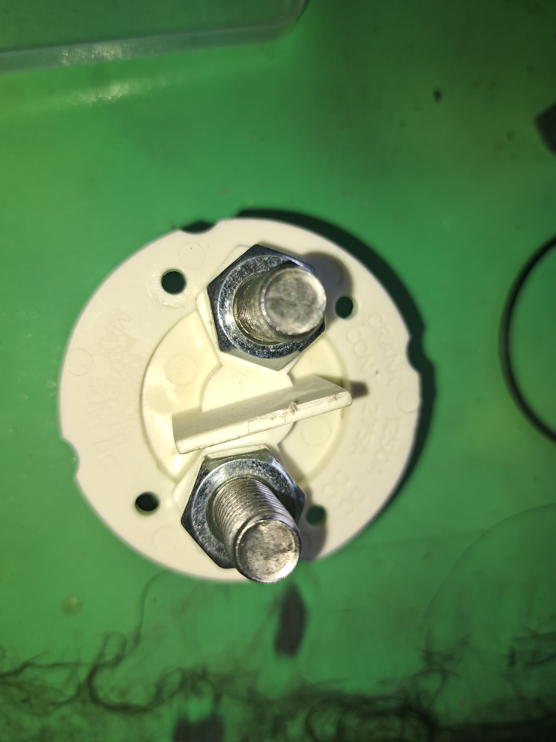
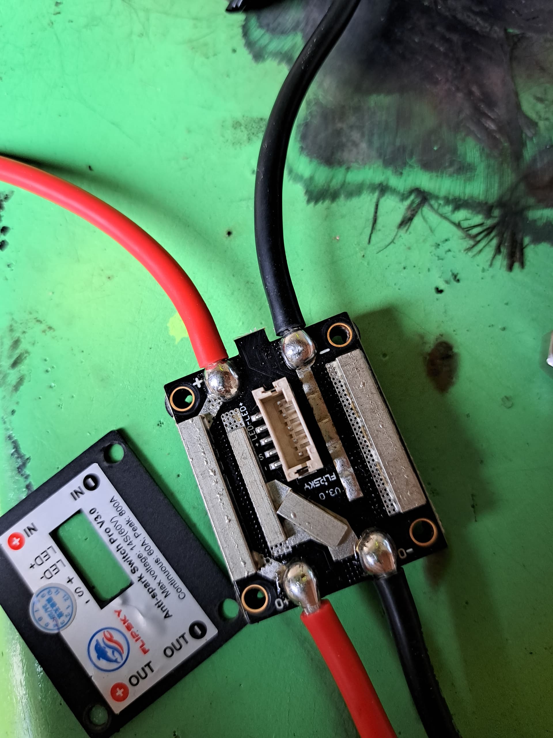
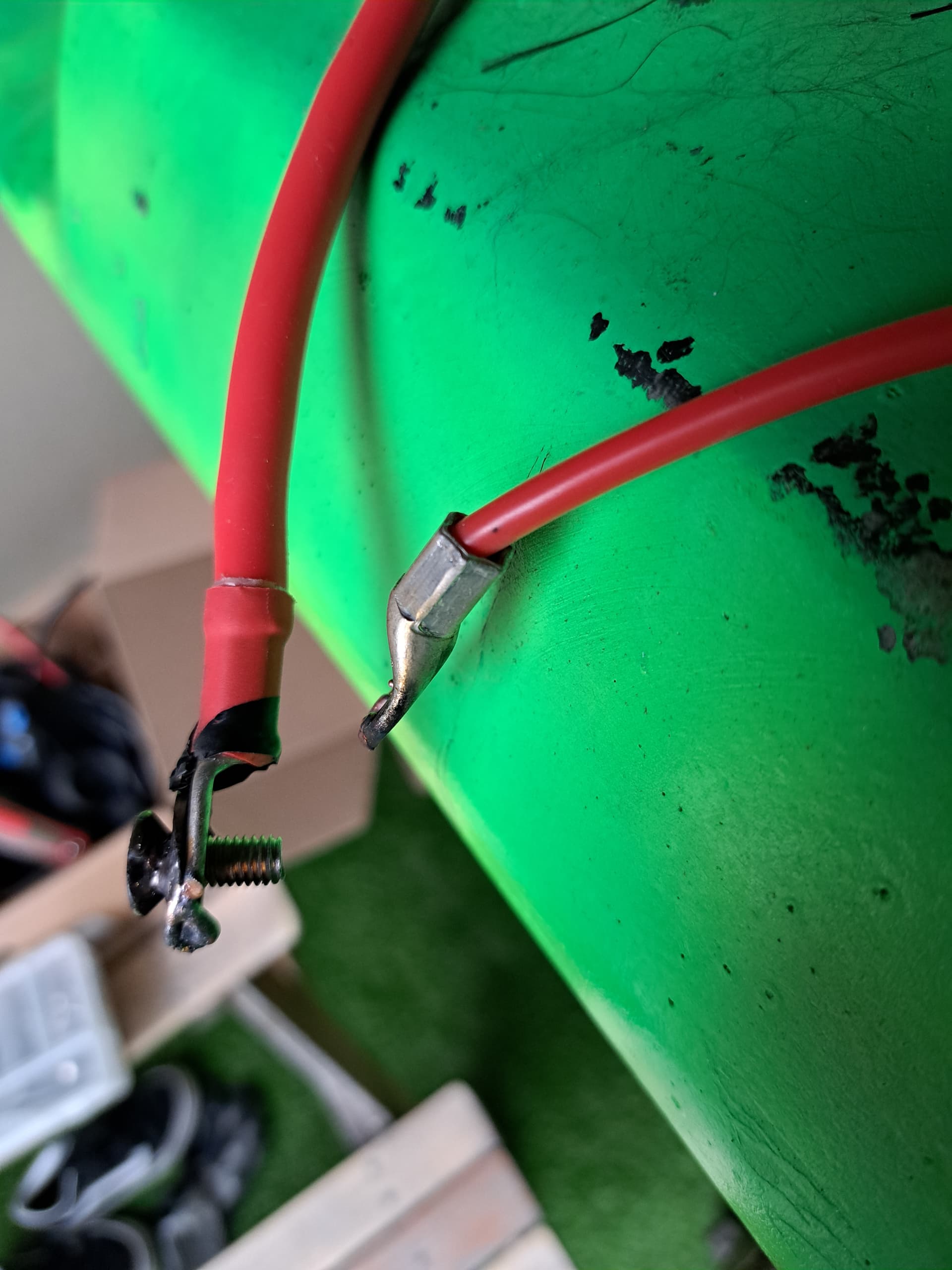
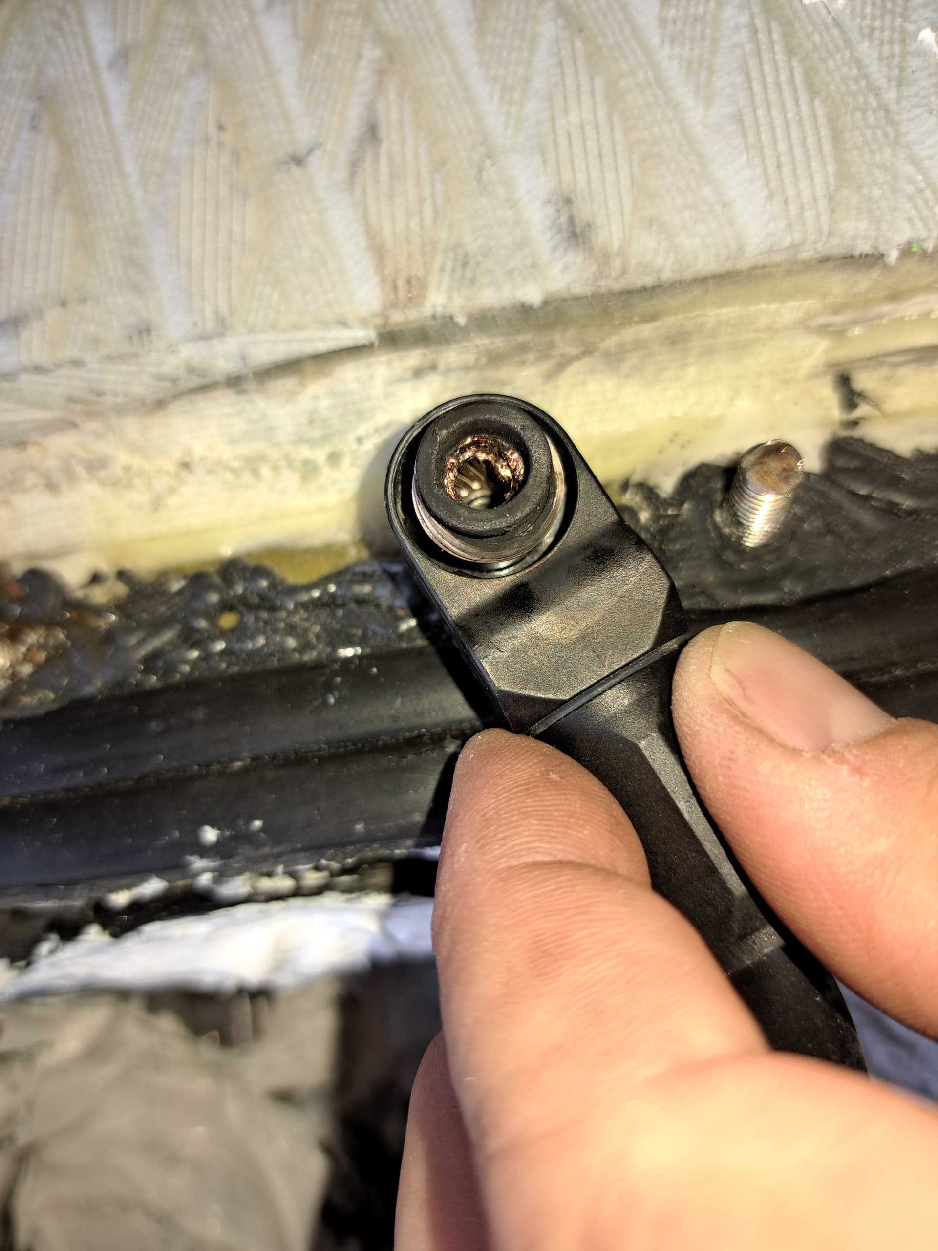
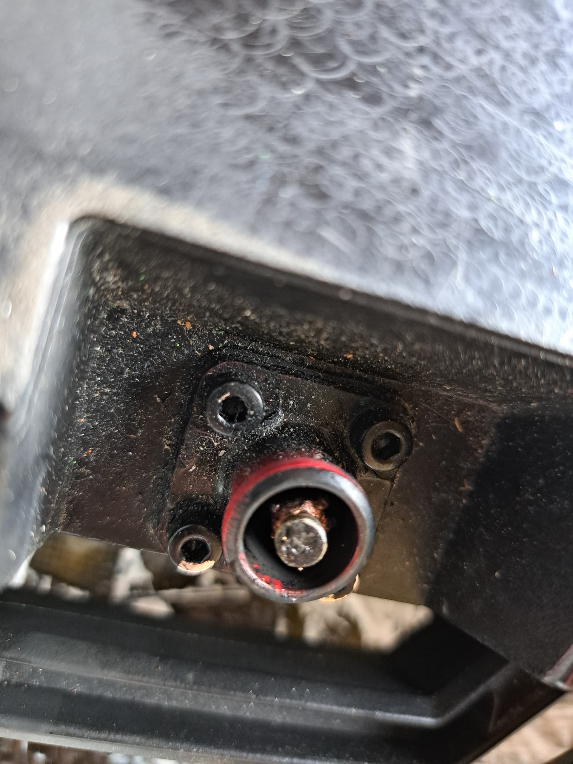
The test carried out a while ago has been disastrous. The antispark switch seems to have not suffered any damage, at least aesthetically. But the male connection between the battery and the antispark switch has taken a good hit.
Why not just use an anti spark connector like xt90s or a beefier QS8. You can also add a 2nd wire with a resistor i. e. 47 Ohm in series to the plus pole of your ESC. Connect that before you connect the battery + to precharge the caps.
The male connector is painted black, but inside it can be seen that it has been completely deformed, and the female one as well.
Just out of curiosity, how much does a 12S battery between 8P and 12P sealed cost? I live in Spain. I don’t want a Chinese product for this component
I’m desperate with the foil.
Regards
Perhaps post a photo of the entire electrical setup rather than the closeup of damaged parts.
I think you have made this way more elaborate than what is required or your thinking that certain connections have to together all the time.
Try to make the connection of the battery to the vesc as simple as possible with a minimum of connections using short lengths of 8awg wire equipped with robust anti spark connectors on the ends.
I personally like AS150 as I can manipulate them easily - the XT type I seem to struggle with. The insulators on the AS150’s are color coded so not likely to plug red into black!!
The only other thought I had is your rig is pulling very high A to start and/or foil and the connections etc are getting hot and deforming.
Do you have any data from a log for Amperage values?
Yes, I think that is the best way, it is the one that some of you have pointed out. But now I have a doubt, if I use the resistor, since it has that antispark-switch, I would only have to do it the first time, right?
Once there is continuity, is the antispark switch the one that is in charge of not firing the shots with its button?
if you use anti spark switch, no need for the resistor. Just be sure the switch is in off position when you connect the battery.
BUT be carefull. Somehow antisparkswitches do not like the vesc motorrecognizion. I killed 1 of them before I found out
Hi, simply as soon as I connect the battery to the VESC or the spark arrester, it starts to explode. I have tried the resistor and today the 12x12 battery has burned the BMS. I am going to disassemble the cells 1 by 1, and mount another battery with a new BMS and make sure I have good spark arrester connectors. Tomorrow I will try with a 12s3p battery that I have. Right now I think the problem was more in the battery, I don’t know. Tomorrow I will post photos of how the battery has turned out.
You have a short circuit somewhere. There is no way with 12S you should be burning through an AS150. You need to check all the connectors and components in this build ASAP.
Agree with Jezza. You might’ve a short circuit in the esc so that it’s now basically acting as a full current circuit. Mosfets can fail closed.
A simple continuity or resistance test with a multimeter would find it. If the esc is shorted out then you might also be able to feel it on the motor, turning resistance by hand will be a lot higher and also increasing with rotation speed.