I own a Fliteboard Air Pro and love it. Unfortunately I also own a Takuma Carver 2 that is troublesome (to say the least). I don’t know how many other Takuma owners there are out there but I am happy to offer my board up for testing and tear down. I have scanned this forum but it seems not much is known about these boards.
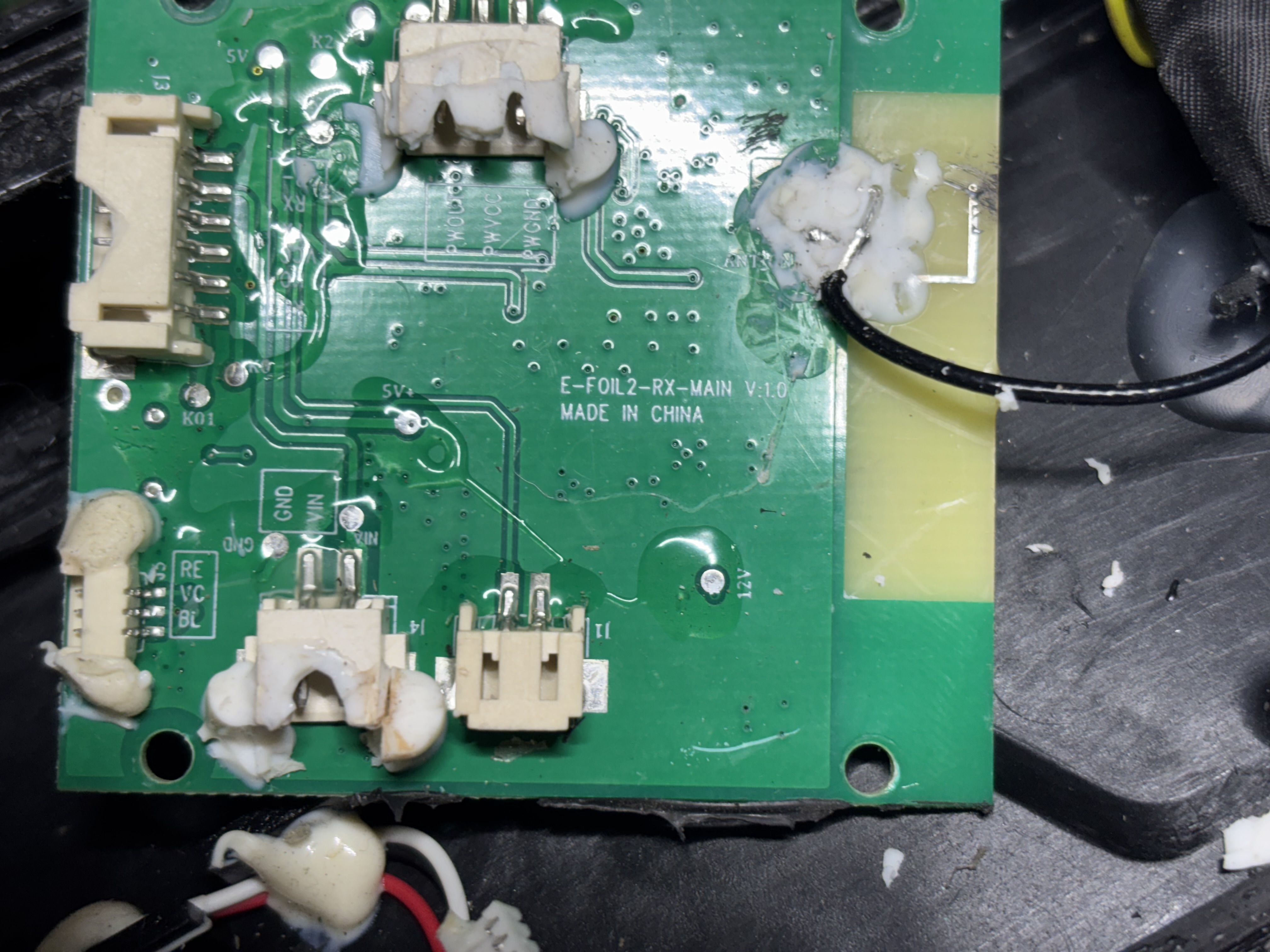
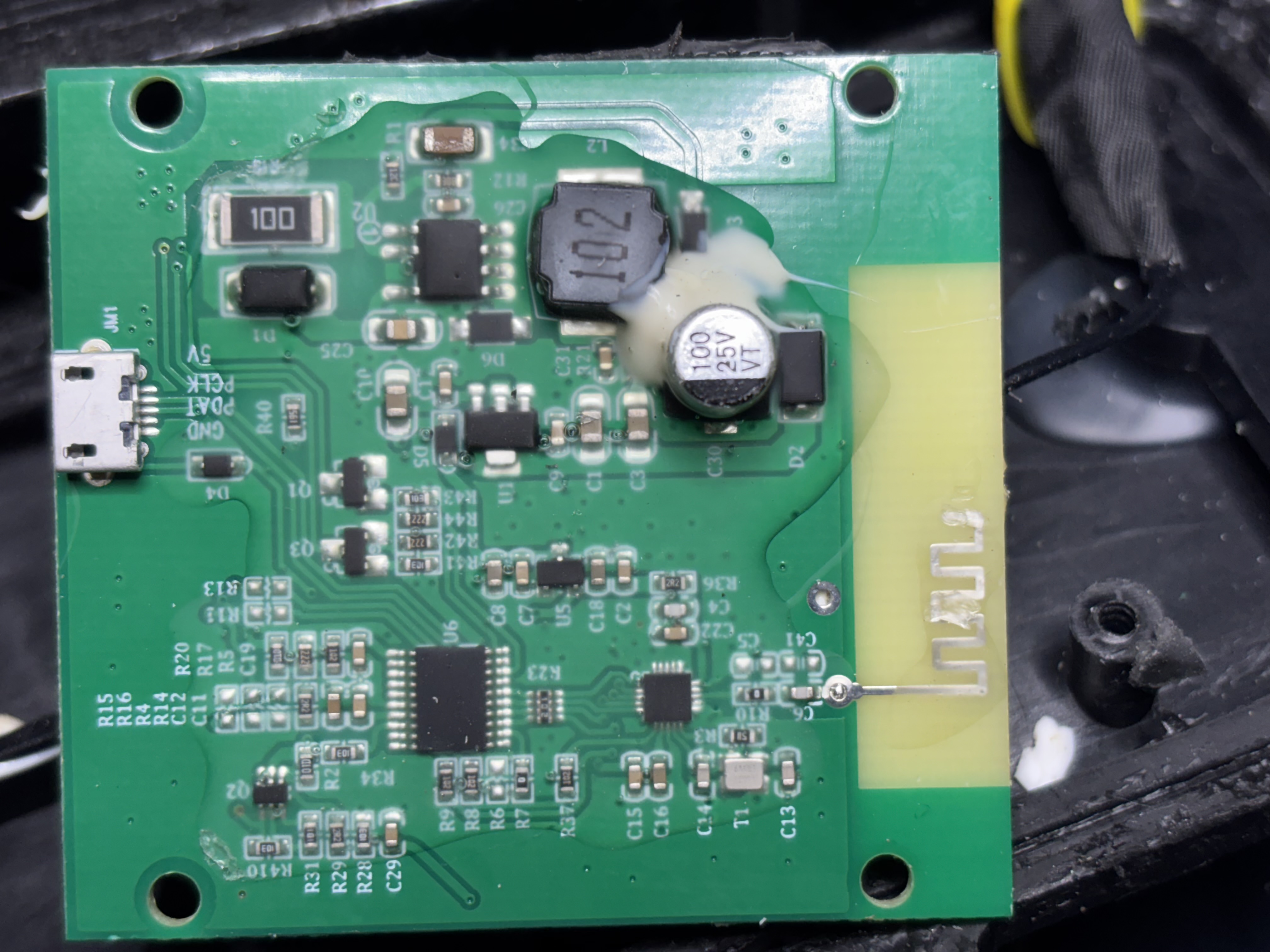
My remote is water damaged. I have opened it up and can share images of the PCB and components if anyone cares. I don’t know enough to identify the BT module but was hoping that it was off the shelf and I might be able to use an aftermarket remote. The controller used to make an RC type pairing noise (not like the Fliteboard which is very proprietary).
If this idea (finding a replacement remote) does not work, I am happy to open the controller to look for the receiver board. Perhaps this can be replaced with the remote.
If this doesn’t work I don’t think i will spend money on a VESC because the board is not that great and the motor is weak.
Assuming there is room putting in a Flipsky VESC bluetooth module and remote would be relatively easy. I only paid like 70$ for my Flipsky remote on sale and it’s excellent. That’s the nice thing about building your own rig the parts are easy to get and replace and you don’t have to pay the outrageous markup of the big brands.
@Windigo thx for the response. I have been trolling Flipsky’s site. Would this be the remote?
Using the existing Takuma esc, i assume it would be easy to confirm whether it uses vesc or ppm. Is this where the fun starts because one needs to understand what signal the esc expects or is there a standard that makes it “plug
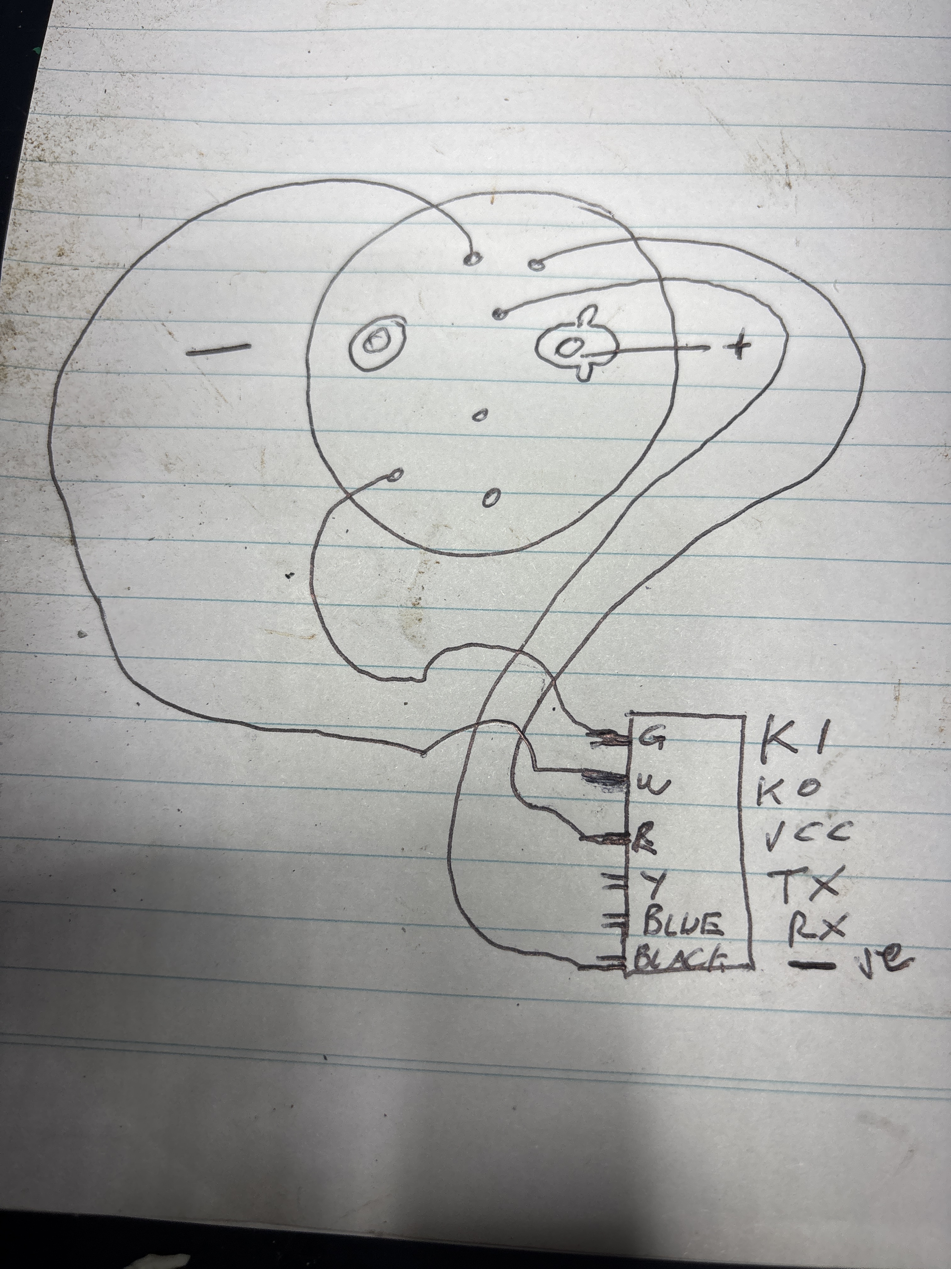
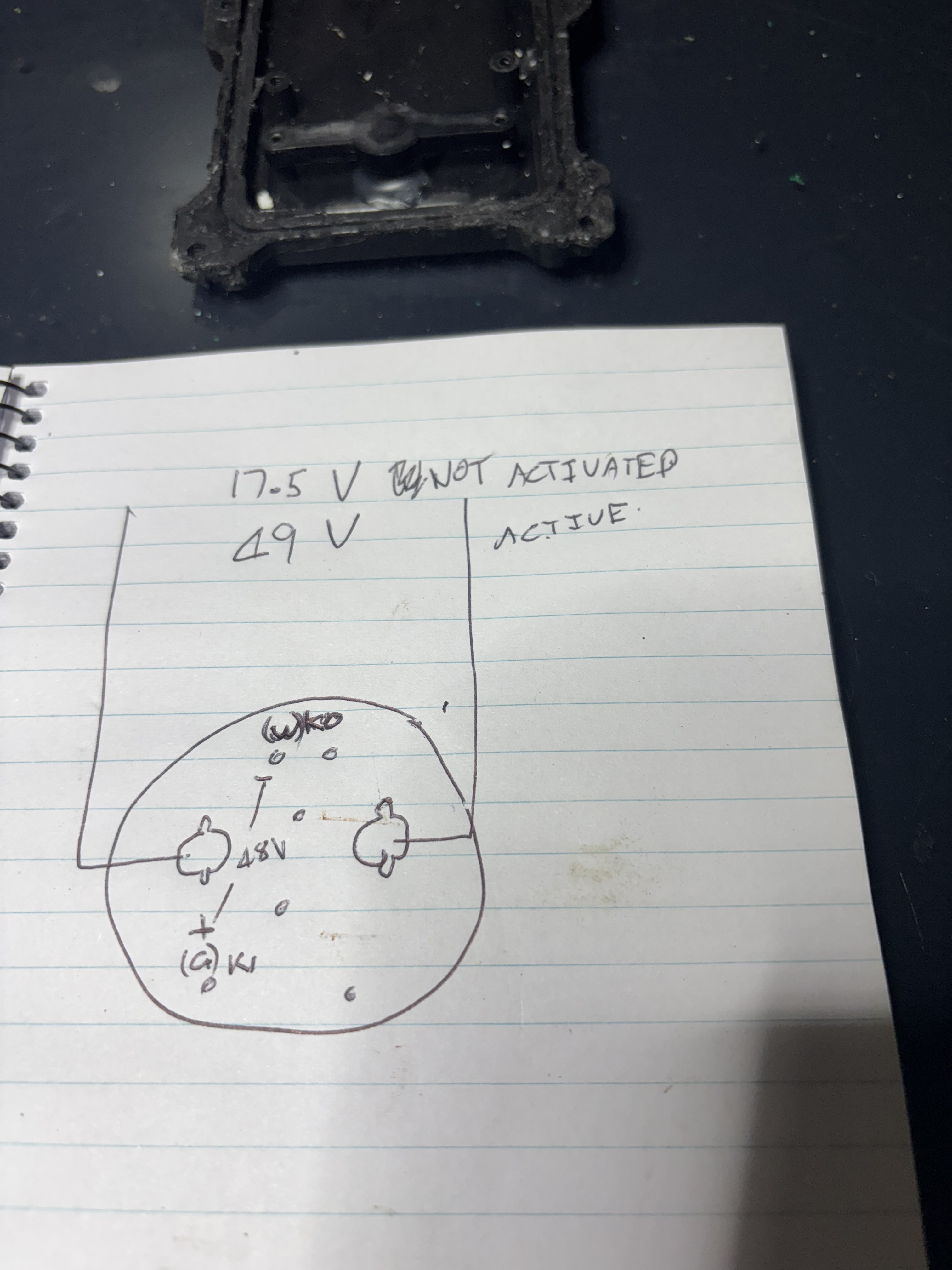
In an inactivated state the battery provides 17.5 volts
Activated it provides 49v
There is no voltage across any combination of small pins except between K1 and K0 where there is 49v with k0 being -ve
Update. I have ordered a Flipsky remote and receiver. Will connect it and see what happens. If it works using std PWM (1ms high to 2ms at a frequency of 50Hz) then i will have been lucky. Otherwise i will write a Arduino script to test a bunch if configurations and once I understand tge ESC expected signal, create a separate script to intercept the receiver output, modify it and output the appropriate signal.
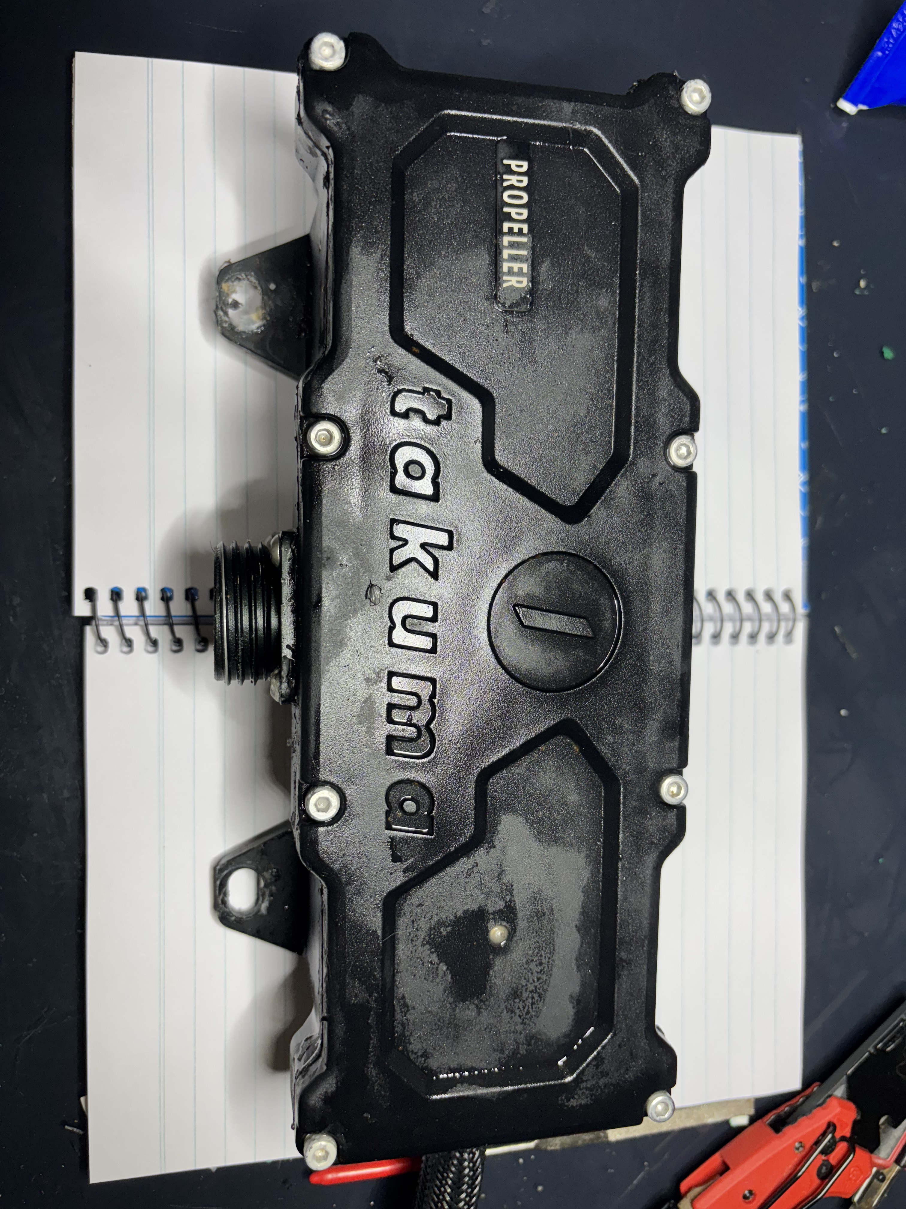
Hi, i have a broken antenna on the esc of a Yakima carver 2. Do you have a trick how to open the esc? It is pretty sealed and won’t come off after removal of the screws
thank you