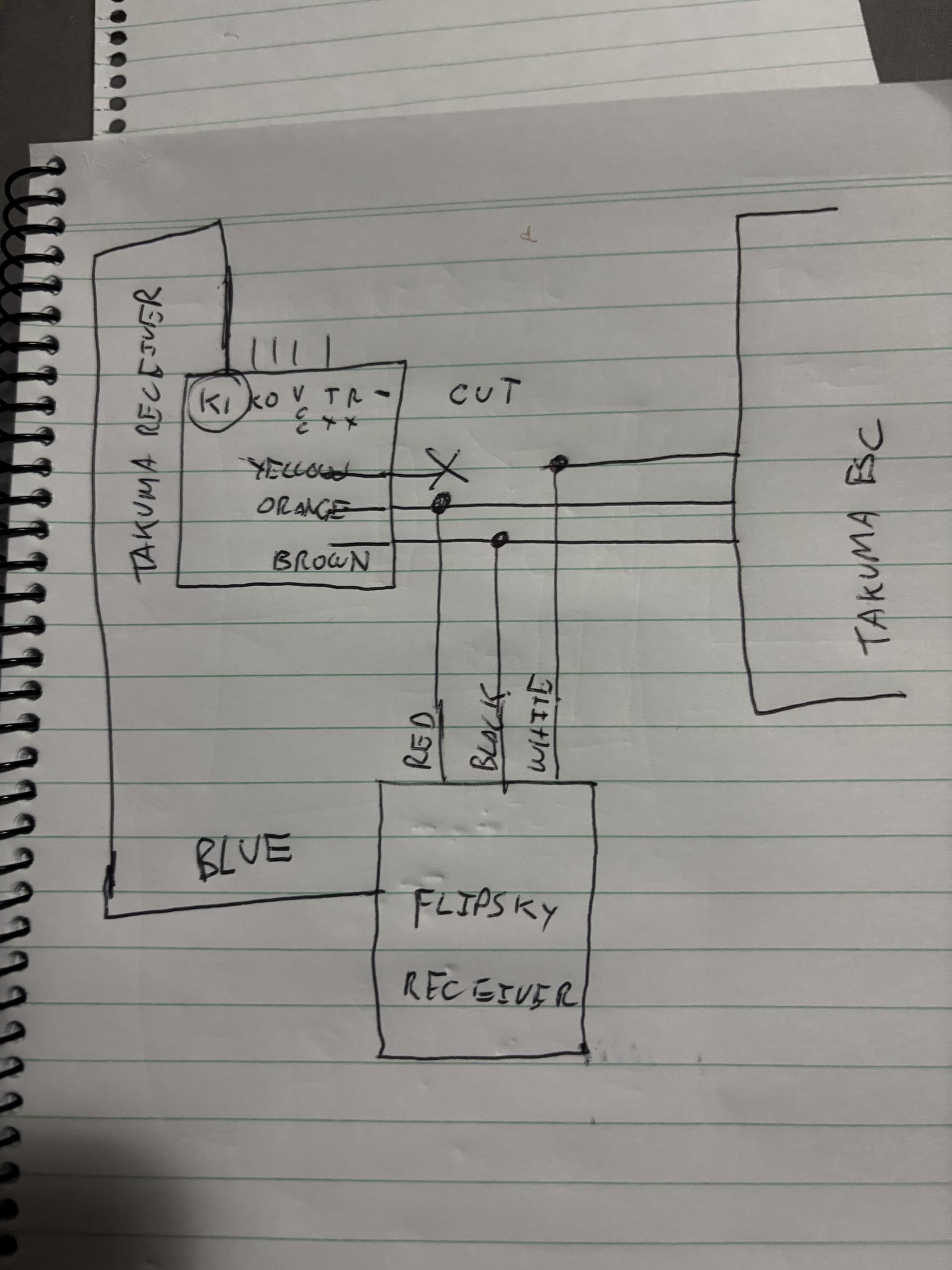
In a previous thread i explained why I undertook this project and will share all my findings soon. Bottom line is that I can confirm that the Takuma receiver puts out a PWM signal at 50Hz. Zero throttle it send a high for 1.5 ms and at full throttle around 1.9 seconds with the boost button taking it to 2m.s. This great news since we can use the “braked” Flipsky profile to manage the ESC with no mods to anything.
I found the 5v “BEC” too. So that’s good.
BTW i read the Flipsky and Takuma signals with a really simple arduino sketch and circuit.
Question: does the Battery Voltage wire on the Flipsky receiver, attach directly to the +ve battery terminal or is it conditioned? Seems scary to put 50V into a PCB.
When you use a Flipsky VESC it comes pre-wired it just plugs into the UART or PPM port. You can look up the specs for their 75200 or 75100 controller. I also think putting high voltage in the tiny circuit is a good idea.
@aussieatlarge …have you done a wiring diagram for this?..i would be interested in doing the same thing for my Takuma setup…i use mine on a tow boogie and would like to implement a more comfortable remote.
Cheers
K
Interesting thread.
One question about the arduino sketch.
How did you read in the data?
I am trying to do the same with a MGM Compro ESC and arduino. Therfore I use a Teensy. It is more powerful.
But I am struggling with the reading of the CAN Bus signals from the ESC.
So if you can provide some ideas
Canbus is best read with a canbus add on board and canbus libraryt file. There are plenty of scripts online to follow. There may even be a sample script with the canbus addon. I’ll take a look later.
Mine was very easy. I connected pin 2 to the receiver and simply read the duration for high and duration until the next high. Added low and high to get the frequency. Then plotted everything through the serial port. I think it was 6 lines. Ask ChatGPT.
const int pwmPin = 2; // Pin where the PWM signal is connected
void loop() {
// Measure high and low pulse durations in microseconds
unsigned long highTime = pulseIn(pwmPin, HIGH);
unsigned long lowTime = pulseIn(pwmPin, LOW);
// Calculate period and duty cycle
unsigned long period = highTime + lowTime;
float frequency = period > 0 ? 1000000.0 / period : 0;
float dutyCycle = period > 0 ? (highTime * 100.0 / period) : 0;
@aussieatlarge
Thanks a lot for the documentation.
I have ordered a Sparkfun module for CAN.
Why, I am using quite often the modules from them.
After the arrival of the module, I will test it out.
Thanks again
All good mate. Took the Takuma out today for the first time. What a pleasure it just connected with no hassles. Board is still a dog to get on plain but it’s not the remotes fault. I noticed that the GPS shows speed. That was pretty cool. One thing I don’t like is that the trigger is still live after a fall. I was hoping it would lock so i will check the settings.
Does anyone know what you can do with the GPS. Is there a session one can download like on the Fliteboard?
Btw. My Fliteboard struggled to connect for 30 minutes. It’s been getting confused since i lent it to a buddy who paired it with his remote.
You have to hookup their bluetooth data module it’s only a few dollars and you can download you session to a phone. I don’t bother I just use my Garmin watch to get my sessions stats and GPS route.
VX3 no “lock” function other than at power on. I flip mine around 180d when climbing back on to reduce potential for bumping the trigger - or you can power off to be really sure.
No GPS log function in VX3 itself. Not sure if Takuma esc can do that via VescTools logging.
Hey @aussieatlarge — really appreciate this thread, your PWM/BEC findings
unlocked a path I didn’t think existed.
I’m running a related project on a Takuma Carver 2: my OEM battery is gone
(lost, no donor available locally), so I’m planning to source/build a
third-party 12S pack and keep the Takuma ESC and motor. Your work solved
the remote side; the open question for me is the battery side.
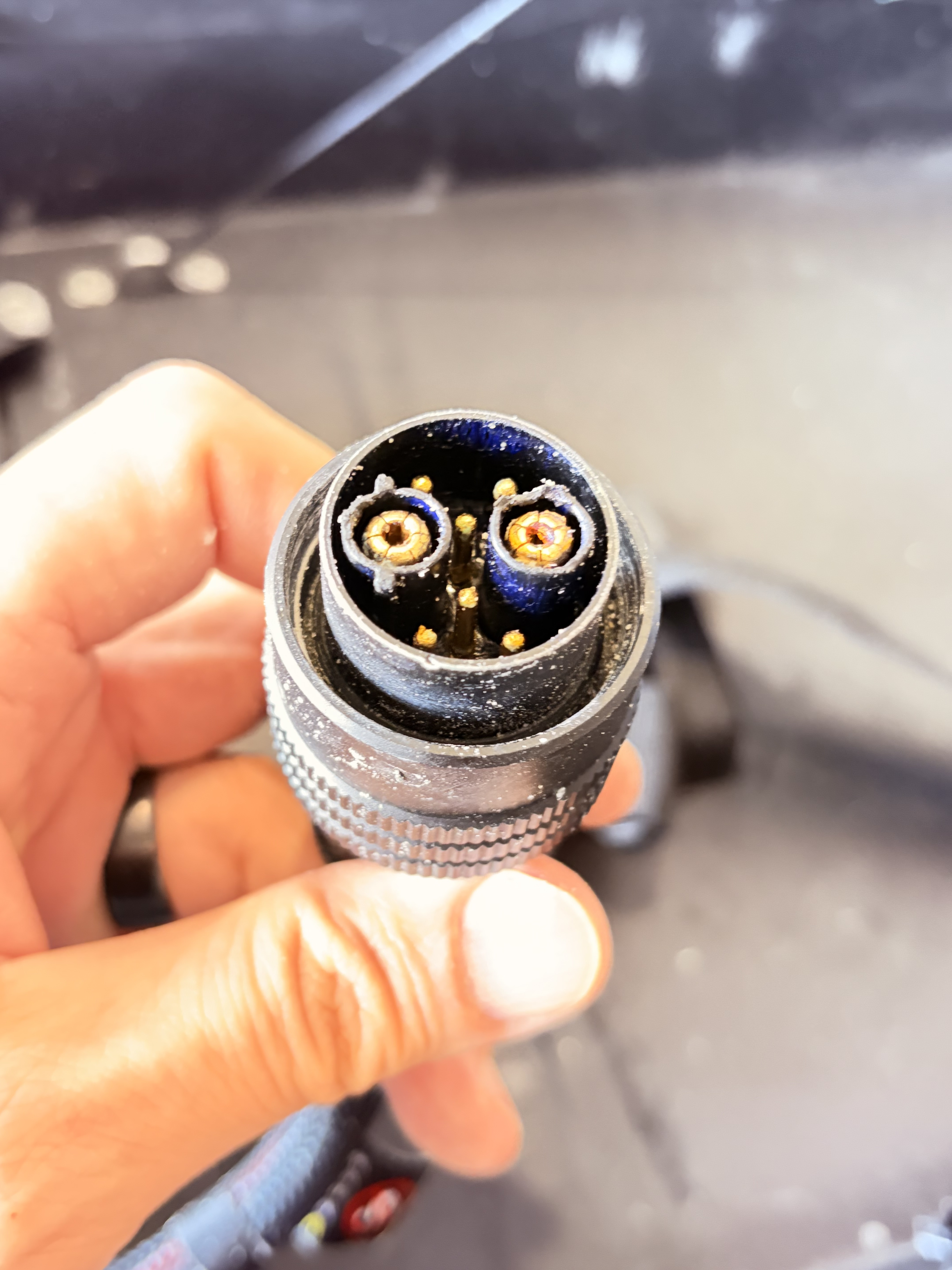
The OEM battery↔ESC connector on mine has 2 large power contacts + 5 small
signal pins (photo below). Quick questions if you happen to know:
Will the Takuma ESC power on and run with only B+ / B− connected,
leaving the 5 signal pins floating?
If not, is any of them a wake / power-button signal that just needs to
be pulled high or grounded?
Are any of them BMS comms the ESC actively reads (temp, SoC), or are
they passthrough to the OEM battery’s power button / charge LEDs?
Even a “I never traced it, but the ESC definitely needed X” would help.
Happy to document and share whatever I find on the battery side back to
this thread — figured it would round out your remote-side work for anyone
else trying to run non-OEM batteries with the Takuma electronics.