For some reason, I keep blowing up the GPS antenna all of a sudden (two times a Beitian BE-280 and one BN-280).
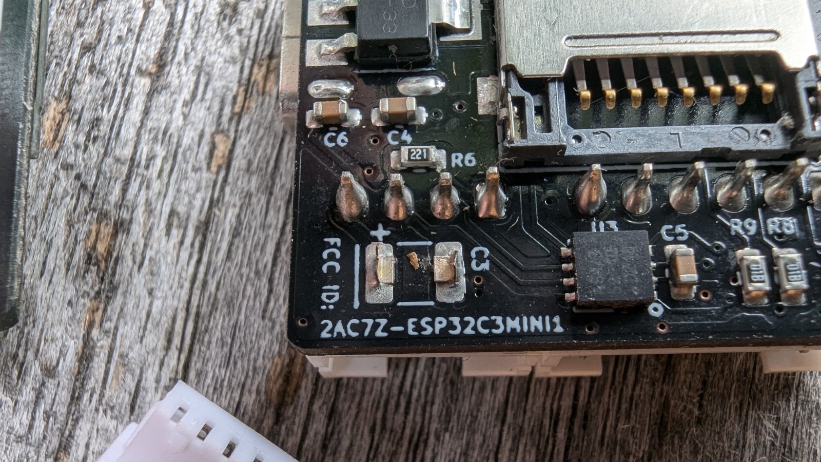
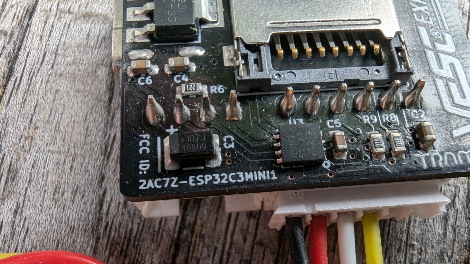
The GPS antenna is connected to a VESC Express, and after “killing” the second GPS, I took a close look at the VESC Express and noticed that an SMD capacitor was missing, which likely fell off when I was rearranging the wires some time ago.
So, I got a new VESC Express, hoping that would solve the problem.
Well, today, I noticed that the third GPS is dead too. Both VESC Expresses still work fine and log everything except the GPS data.
Dead meaning NO GPS lock (yes outside, and yes waiting a long time), and also NO packets coming in at all!
When I connect a new GPS it almost instantly gets a sat lock, and shows incoming packets)
The VESC Express is connected the same way (nothing changed) and it used to work perfectly.
It is using the CAN from the 75200 (+5V, TX, RX, and GND).
I think this might be happening when I change the battery. Could it be a voltage spike on the RX line?
I’m now on my last (4th) GPS, but I’m afraid to actually use it in real action in the board.
The GPS puck itself is 3.3 volts, but the Vesc Express is taking care of this.
I have done some measurements on the bench, and all within the voltage it should be except the GPS GND / RX (and what I think is broken)
CAN:
GND / + = 5.02 volt
GND / CAN Low = 2.53 volt and after some seconds dropping to 1.67 volt
GND / CAN High = 2.53 volt and after some seconds going up to 3.43 volt
GPS puck (so after the Vesc Express)
GND / + = 3.3 volt
GND / TX = 3.2 volt
GND / RX = 3.19 volt spiking up to 3.5 volt* for a second, and back to 3.19 volt
(*my volt meter is probably not fast enough to measure the exact voltage spike, and I do not have access to a scope to measure it exactly)
As the error I get is “no packets coming in” I think that the RX part of the GPS is blown.
Now. What could cause this “spike”, and even better, how can I fix this?
It’s the 2nd brand new Vesc Express, and I do not think that this is the issue.
Yes. The ESP32 is located right above the phase cables (maybe max 2cm above it)
GPS puck is located above the plus and minus of the battery cable, and about 5cm from the 3 phase cables!
Wow… Thinking of this, this could be the problem!
Do you maybe have a link about this phase cable “issue” for me?
A search did not help me (till now).
When I was doing lots of development and data logging of the Boogie I noticed that I would get serial drop outs during high motor loads (interesting it was one way - I could still give the motor thrust, but could not get back temp and power values), which is most probably due to throttle smoothing/ramp in the vesc now that I think about it.
I shortened the serial cables, re routed them and put them in a shielded cable and now no longer have the issue.
Same thing happens if you are connected to the vesc via USB you will get disconnects at high loads.
I noticed some weird behavior too until (i guess) the GPS killed itself.
Things like delay when releasing the throttle, and a stuttering motor when under load.
I changed the remote (yes with your one) thinking this was the issue, and needed to pair it again (power off / on the system)
After this all was fine again (guess the GPS killed itself at that moment).
I am going to shorten, twist, re route and shield the cables too and see if this will fix the problem.
Maybe even add a 3.3 volt zener diode to the RX from the GPS to try and save it when things go bad again.
Thank you for the info.
( Last log before it died. Vetr.at Log View )
I think normally just one end of the shield is grounded to avoid ground loops. I had a motor dyno with measurement issues due to noise and spent some time on it… seems shielding noise can be quite complicated, I didn’t succeed really.
It might be good too look at removing the noise transfer. Route logic wires with 90 degree angle to noise source wires, use twisted pair wires or wires within as close distance as possible (goal is to minimise ground loop area), keep a longer distance from logic to noise source.
Thank you for the information.
All was working great till I started rearranging wires, and unfortunately I can not remember how the wires were routed before (must have been lucky that time)
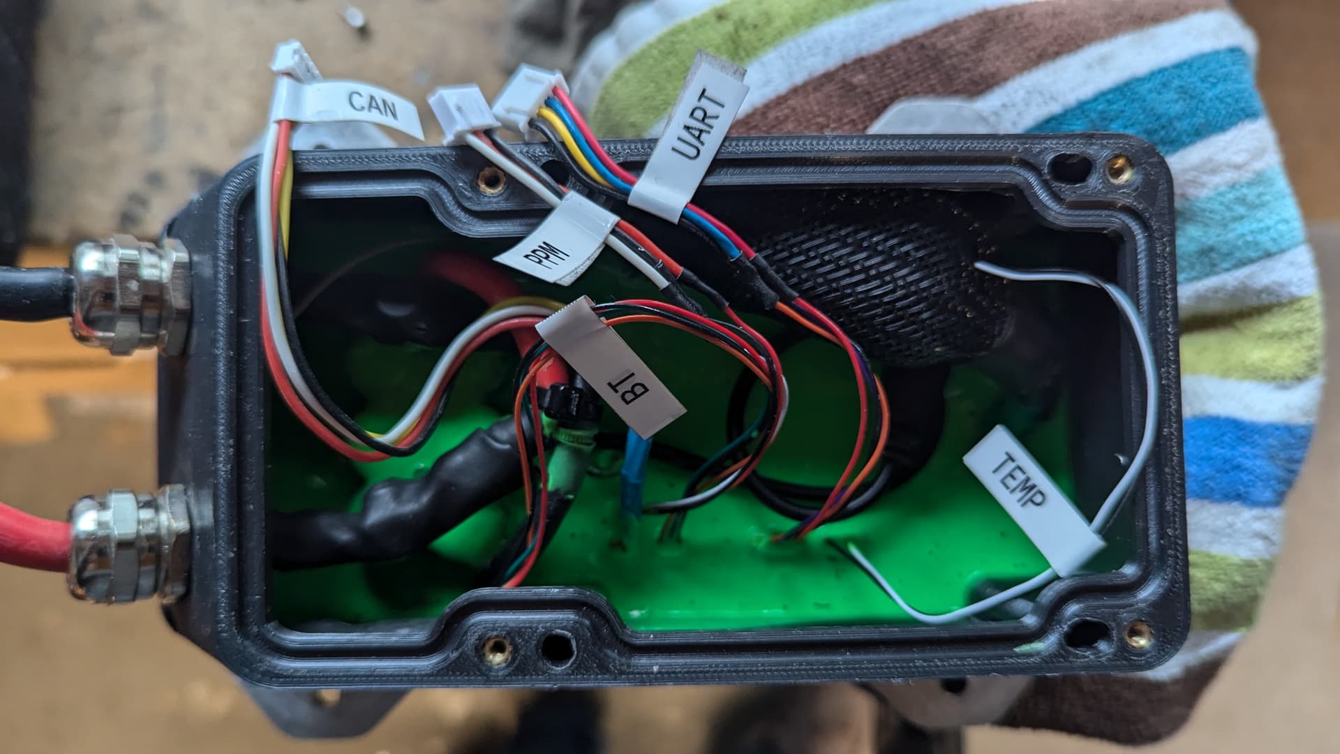
This is the room I have to play with.
The FeRo receiver (not in picture) is also in it :-/